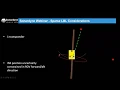
okay so sparse LBL welcome by the end of this session we're gonna be we're gonna know what sparse LBL is and we're gonna understand the performance and the limitations of sparse lbr so they're not necessarily limitations more fine-tuning the system or understanding the best way to have these systems running okay so what do we mean by sparse lbr what do you think before I go and tell you and then we go into a bit of detail with it what do you think I mean by sparse lbr at this particular moment in time just put it
into the onto the screen or into the chat what you think I mean by sparse LBA what is it anybody tell me there is in the title a little bit and there you have a shot you just a couple of words don't need to write anything anything big what do you think it's allowed to be using a partial LBL or any thanks Sebastiano yeah like I'll be a bit more sparse yeah more than an LBO more than an are we actually a fewer fewer than an LBO array okay good right so sparse LBL probably a
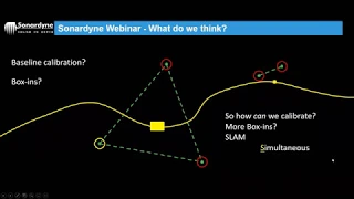
good place to start is with LVL so the full traditional means so we've got this on the screen here we got this full array this Pentagon shaped array probably a perfect array the most perfect array you're likely to see good geometry lots of redundancy we've got five transponders and very good line-of-sight and all that sort of stuff so a very good array over here this side we've got a square array for transponders but we've still got very good geometry okay but how do we calibrate these things just as a recap how would we calibrate these
two one word or two how would we can have a nice anybody got anything you no no answers first geometry of the array then box in okay yeah thanks Sebastiano yeah so what you mean by geometry of the array somebody else has put boxing on the screen yeah what do you mean by geometry of the array is I guess some kind of relative calibration so Tom's Tom's put their baseline relative cow right so we're gonna take baselines between all our points on the on the seabed here same over here we're gonna measure that the distance
between them you're gonna feed that into a piece of software we're gonna mathematically adjust where they all are based on the range that we that we've measured and that we hit so that said that's what we'd call a relative calibration we're also gonna tie in depth somewhere as well off for 3d positioning somebody's putting box in and a few others put boxing into the chair yeah we would also box in so potentially these two here the reason we do these two here is obviously the longest baseline the reason for doing the longest baseline as we
talked about in the LBL webinar two weeks ago was to constrain the orientation of the array if we just boxed in one of these array when we did the calibration it would be allowed to pivot swinging about that point so by having another constrained point over here we can constrain the orientation of the array when we come to do the calibration okay sorry with lvl justjust just continue the recap once we fix these references on the seabed we've got four transponders in this particular case we've got good geometry we've got lots of redundancy usually in
this case we've only got four but but but we've still got redundancy and the rules of LVL always say that we need a minimum of four ranges to derive position okay so in this scenario we've got four four ranges we can position this vehicle quite nicely within that space okay and obviously with an lvl array as we talked about in previous webinars we would be working within that environment within that array okay we couldn't move out here necessarily or we could but the positioning wouldn't be quite as precise okay so we're working within the array
with an LBO so let's change that to a sparse LBL scenario we've reduced the amount of transponders on sea bed now we've only got two whereas before we had the the other two at the top you many see it referred to as a sparse array you may see it referred to as range aiding or hybrid navigation okay they all mean the same thing pretty much we're using the range information from subsea transponders in order to feed our NS on our vehicle okay we're not feeding an lvl position to the vehicle to the IMS so l
BL does a least-squares adjustment whereas range a did I and s it will take the range information and then the I NS will predict it's the position of the vehicle based on the range information in the Kalman filter of the ina okay we reduced in this picture the obvious answer is we've reduced email transponders but by reducing the amount of transponders what else will be if we reduced anybody tell me redundancy thanks to bestie on oh yeah excellent we reduce redundancy okay so we've got less redundancy and therefore our four range minimum is unachievable okay
so if this was just a typical scenario we didn't have a 9s it was just an LDL scenario if we only had two ranges we wouldn't be able to position the vehicle because but we're gonna be able to position the vehicle with any confidence because we haven't got enough range okay you'll notice also in the picture the position of these transponders relative to the vehicle they're actually strategically placed in order to maintain geometry okay so you can see we've got one out here which is to the side of the vehicle on one out in the
in the forward half direction of the vehicle okay so this is what we'd call management manage geometry we've had to manage the geometry of the system in order to to maintain the precision of the position of the vehicle utilizing the ranges but as I said earlier we've added the i-ness so so I talked about this is just a solely lvl scenario but because we've added the 9s that's first oh sorry excuse me because we've added a 9s be we've got that the short term gain short-term accuracy gains of of the iron s yeah it will
hold its position for short periods of time and that will be a very robust position but longer periods of time it starts to drift as we talked about last week we're combining that with the long term accuracy of our LVL system so our range arrange aidid range system so as we know the the environmental effects the short-term effects on on an acoustic system is is causes causes fluctuations in positions sometimes so by combining the two systems the i ns system and the acoustic system we've we've we've got the best of both worlds okay so short
term actually v9s long term efficacy of the acoustic system gives us the best of both worlds it's basically okay so just to recap something we did last week don't worry about this slide there's lots of information on there I completely appreciate that bit I want to basically touch on is this section down here okay so this this was where we talked about the way the AI NS works but we've got our own s algorithm here this bottom pink section and this will produce a position estimate based on based on movement and maneuver the movements of
the of the vehicle yeah it will predict its own position and it will when we get an observation from from from an observation such as a DVL or a USB a lot I mean it will compare that estimate that it's produced with the incoming observations okay once once once if the incoming observations agree with the estimate then they're allowed this error state Kalman filter and then that will fine tune the position estimate basically so utilizing the observations to fine tune the position estimates of the island so the thing I want to recap here is is
obviously this LBL section here so for sparse L we are we're using the range information from our subsea transponders so this is the section we're talking about here so so although it says lvl as I said earlier it's not actually lvl its range aiding okay so we're feeling the range of information into the Kalman filter Kalman filters then utilizing that range information in order to correct its position estimates okay that's all I wanted to say about that slide so so don't worry could be covered quite a lot of detail about that one last week but
I've also mentioned this term manage geometry so what do I mean by that that's have a look in the picture here I've got this this ROV it's navigating down a pipeline we've got over here we've got a subsea transponder and then out to the side here we've got a subsea transponder okay so we're going to navigate down here and we're going to collect a range into our iron s from one range from the side or from the crosstrack direction and what you can see in the picture is that the range is constraining the air ellipse
and the direction of the range okay so the air ellipse elongates in this direction because this is forward aft this is cross track okay so the range is constraining the crosstrack error okay and the forward half direction is also being assisted slightly by the direction of travel of the vehicle okay so the the Doppler observations the DVL observations are in the forward half direction the the Insp movements are in the air in the forward half direction but that is helping to constrain this error lip slightly in the forward half direction as well so the reason
I'm telling you that is obviously when we when we started talking about this technology this sparse LBL technology we initially said you can essentially use it with one transponder that is still the case she could still use it with one transponder but we've since actually said them that it's better to use it with three transponders as a minimum just for 4qc and also redundancy okay and the reason being is obviously with one transponder you can see that the dangers in the precision of position if you if you're if you're only using one range okay so
your error lips is going to elongate in one direction based on the orientation of the range okay so obviously your position precision is going to be somewhere within this error lips so when utilizing one range in a sparse LBL side of things then it is possible to change the geometry of the whole thing just by switching the heading of the vehicle okay so in this case this is actually the best scenario for utilizing one range because direction of travel of our vehicle is in is in the perpendicular direction to the range which means it's going
to help constrain the arrow loops in both axis does that make sense to everyone so far just give me a tick or a thumbs up make sure you're all happy you stuff that's basically what we're doing we trying to constrain this error lips as best as possible utilizing the the observations okay good right let's take just just to just go a little bit further with that point if the Rav was traveling towards this transponder the direction of travel of the vehicle and the range would all be in the same direction which means that the error
lips would elongate quite a lot in the cross trap direction okay because everything is now in the same orientation so let's have a look at that scenario let's take the range from behind this time oops no stolen my sandwiches right what I'd like to do is get the tool the tools that we used earlier the circles and draw the ellipse that you think we're likely to see yeah I grab your grab your tools and then draw the ellipse that you like to see we've got one range from behind here so what's likely to happen to
the ellipse so many draw one I even gave you the answer by accident yeah thanks ASA yeah and David good stuff Nelson yeah excellent you create a little stir you good stuff okay so all exactly right yeah it would be in this direction well this has gone a bit controversial there the previous ones were all good this one's a slight obscurity okay say remember remember a so the the range is going to constrain the arrow lips and the direction of the range so this range is coming from this direction but we're gonna squash the arrow
lips in that direction okay let's just clear those down and make sure you're all okay with that oops mouse mouse you see there we go right so that's what you like to see so the arrow lips elongates you can see it's slightly bigger than it was before and that's because our direction of travel of the vehicle with our DVL velocities and Rin s movements are in the same orientation as our range range measurements okay but obviously with with this type of system what we're looking for is a nice equal error lips in order to maintain
precision on the position position of the vehicle so let's take this scenario we've got one out to the side and we've got one from behind we are getting what's called a good angle of cut so we talked about this before angles of cut with it with an LDL system where we're talking about the same things with the sparse LVR system so we just got less transponders to do it with so we got this good angle of cut here between two transponders not quite 90 degrees but it's close to 90 degrees as possible but what's going
to happen to the error lips here again grab your tools just draw the ellipse for me this time we got range from behind and a range from the side so the error lip should do what excellent thanks you guys that's good equals out as best as possible okay so this is what I'm talking about when I'm talking about managed geometry okay so the geometry of this is actually very good even though we've got less transponders so the position precision is still maintained excellent thanks for the drawings that's good there we go that's what we like
to see okay so iron exposition uncertainty we talked about this last week the uncertainty of the iron exposition is constrained in both directions basically is one that's seen so I think we've seen this picture before as well but this this this should all makes sense now hopefully if you understood that last bit this is a pipeline survey let's imagine in RVs navigating along this pipeline at any point in time it's gonna get relatively good angles of cut from these subsea transponders okay so one thing you'll notice is we've only got three so we reduce the
amount of transponder but there were also all on only on one side of the pipeline okay so with a traditional array they would normally be surrounding the pipeline and have them all the way around in order to maintain geometry but in this case because we're using sparse LBL we're combining our acoustic system with an iron s we can just have them all on one side of the pipeline which which reduces our overall deployment costs it reduces our calibration time it reduces the overall cost of the transponders themselves initially so it's obviously a good thing for
the customer so you can see now that that you know even if I was here I'm maintaining this angle of cut between these transponders if I'm collecting the ranges from these transponders and then at some point when I get up here I'm gonna start to collect the ranges from this one in conjunction with this one and that's going to maintain my angle of car again okay so you can see based on what we've talked about with geometry we can plan our sparse array accordingly and you can see here we can spread them out quite nicely
but how does the geometry in the redundancy affect the position of precision of position let's have a look so this is our in-house lvl planning software what you can see on the screen here is we've got an ROV this is a full array in this particular case and what it's doing is just it's just simulating basically the ranges that you like to achieve as you mover outside of this array so one thing different from from lvl is we can actually navigate outside of an array as long as we can collect ranges into the AI NS
we can navigate quite nicely ok so we don't need to work in in the confines of this array ok you can also see some colors on the screen so you can see it's quite blue and if you look at the key over here this is an indication of the precision of the position of the vehicle ok so you can see the blue is the zero point zero zero that's in meters and then up to as it as the red or it gets basically that moves up up to half a meter okay so in terms of
precision in this particular case even though we're outside of the array we're maintaining very high precision okay but let's reduce the array down to a three transponder array so now we've got a sparse array I've only got three transponders and you can see we maintain fairly good precision most of the time as long as we're maintaining good angles of cut but when two transponders are in line with one another as you'll see in a minute when we get down here and these two are in line you'll see that the precision starts to degrade slightly and
that's because we've we've lost lost the angle of cut that we talked about earlier it's actually helping a little bit because we've got a triangle so we've still got a range out to the side sliding when it happens so we're not not degrading it massively but it's still still have a none effect and then what about two transponders so this is a typical this could be a typical scenario with a sparse array it might be a series of compacts along the side of a pipeline so they may be in a long line okay there's no
geometry and you can see what happens when you go between them or out to the side of them when they're in line move on of that look what happens the precision of the position of the vehicle it drops significantly down to about half a meter okay so this is one thing that some people tend to struggle to get their heads around initially with sparse arrays and and obviously because from a traditional array when you when you go between two ranges with it with a traditional array that's usually a good thing because you're getting you're getting
getting lots of redundancy and you get them ranged from both sides but with a sparse array that's actually the worst thing for the is if there's only two compound hey it's death so is everybody okay with that so far everybody understand that geometry is incredibly critical you know when even when we're planning these sparse arrays we need to we need to make sure we thought about that angle of cut that we're gonna get to maintain that error lips very happy that give me a thumbs up or a tic just in the participants have good stuff
and say say you for it yes and the chat that's good right so why would we use this system yeah why are we going to use sparse LBL and to take a typical oil field development we've got lots and lots of transponders lots of redundancy what we may have struggled with initially was getting line of sight between them all because we got all these structures on the seabed okay but quite a large array lots of transponders quite expensive yeah we got transport a lot of transponders initially which is expensive anyway we've got calibrating them and
we've got deployment which is going to take a long time okay so let's reduce it to a smart array we've got less transponders so we've we've reduced the cost straightaway we may have found it easier to get line-of-sight because we've got less points within all this this this these structures on the seabed okay so one of the main reasons and drivers behind this is obviously to reduce cost for the to the end-user especially in this this day and age is one of the big drivers for these for most projects and I guess it's going to
be even worse as we come out of this this particular scenario it is they're going to be constantly looking for cost-saving measures so this is one of those cost-saving measures is to reduce your the size of your arrays but still maintain precision okay so all through here it wouldn't matter too much done we're going to maintain precision we could dip behind structures with our vehicle because we've got an Iron s on it and it wouldn't matter that we lost line-of-sight to some of these transponders because the ILS would hold the position other scenarios so in
this picture we've got three colors you've got the green which is this pipeline so it's probably got a lay