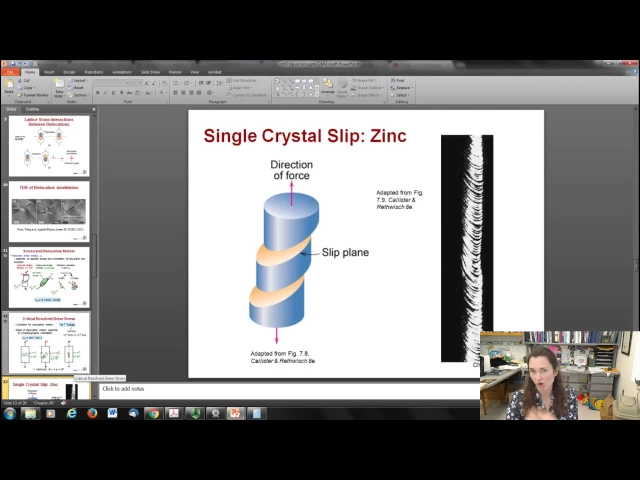
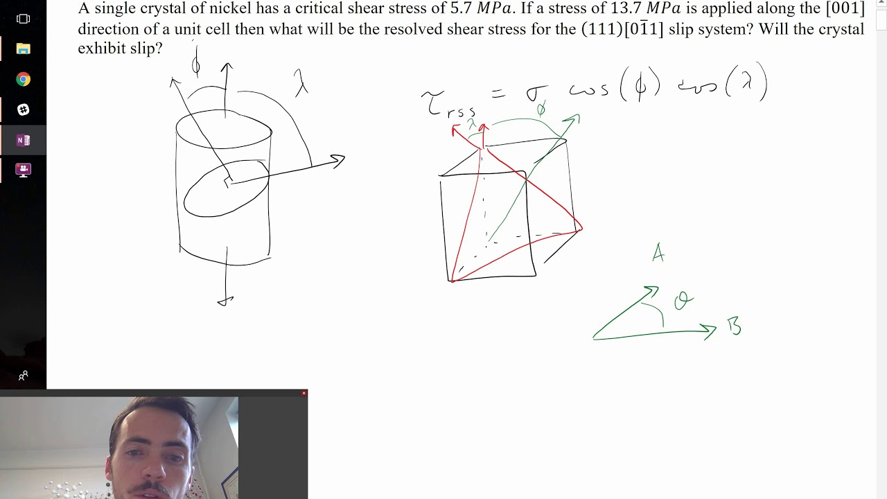
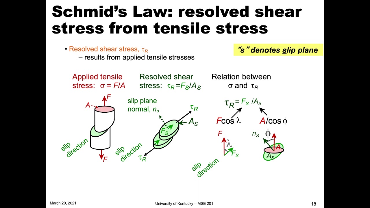
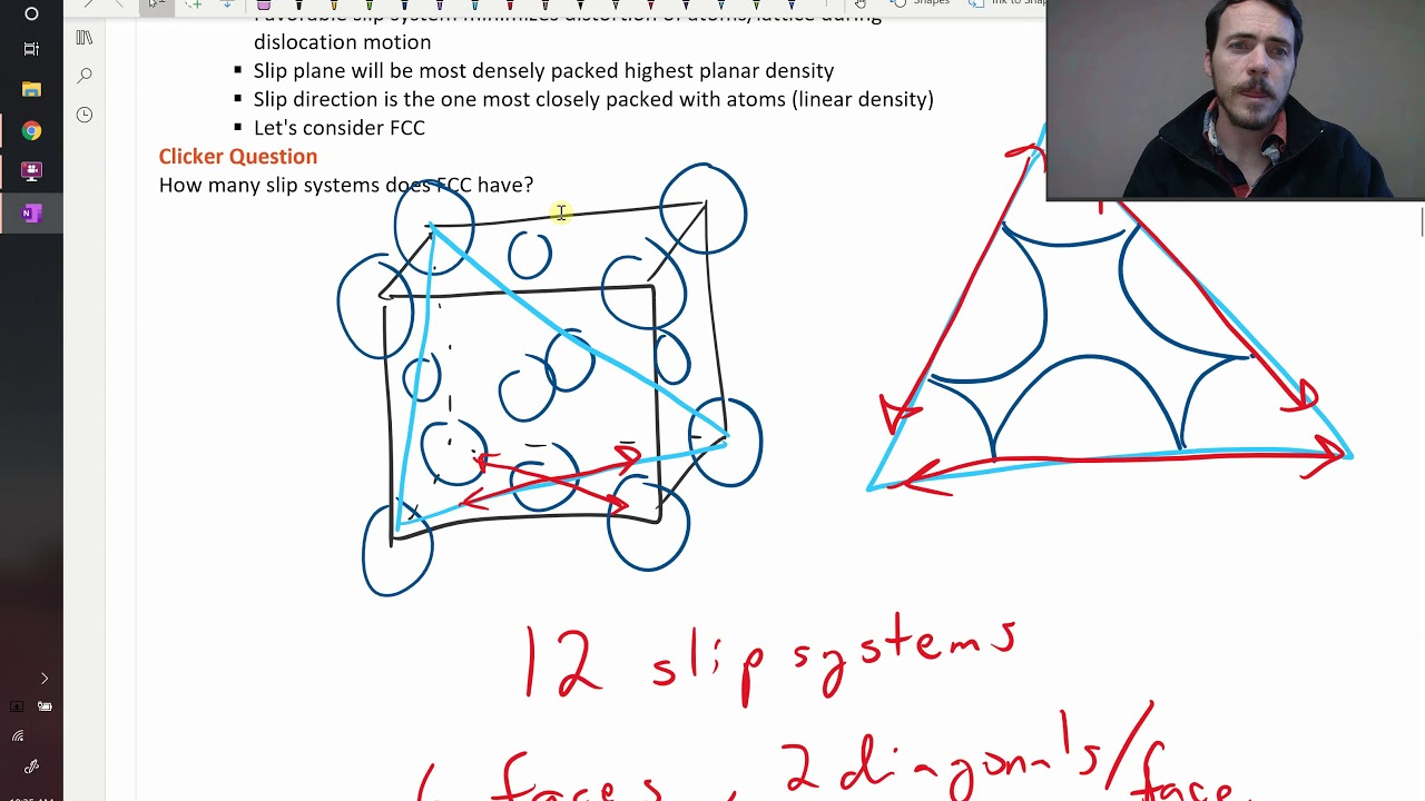
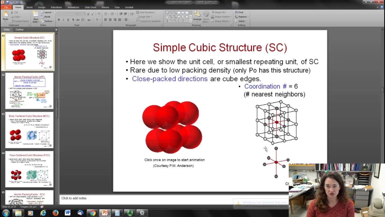
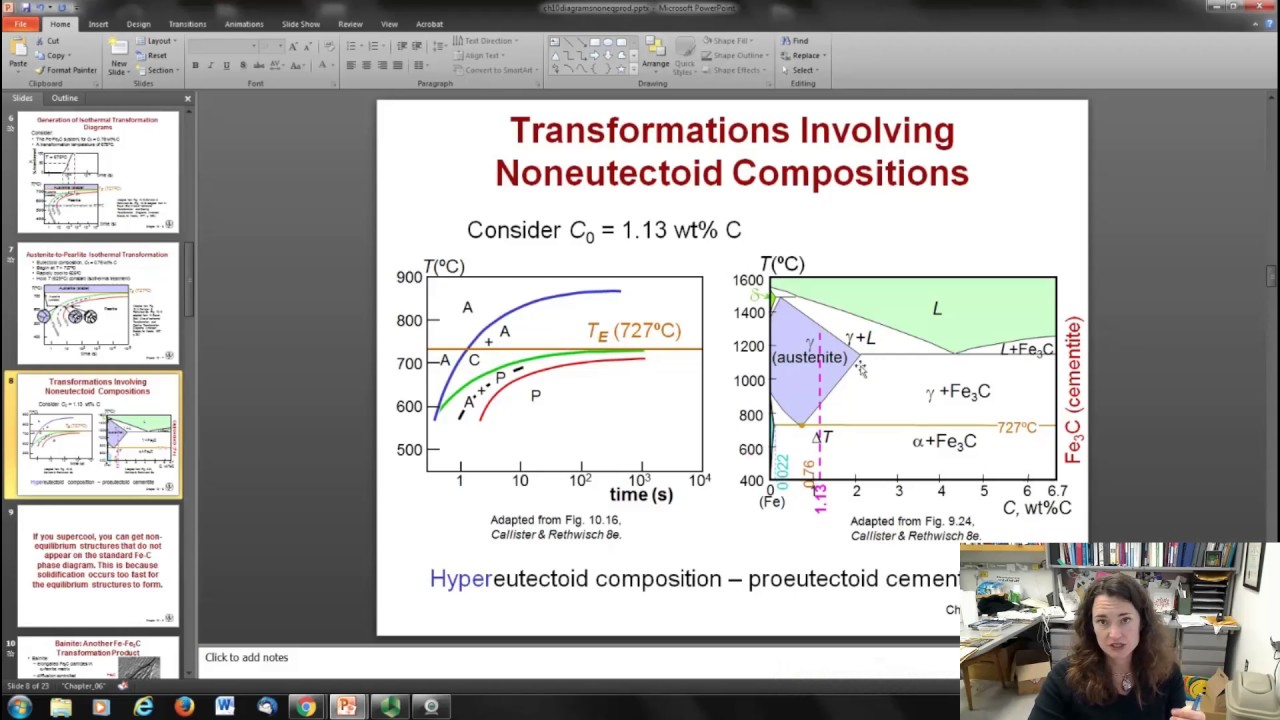
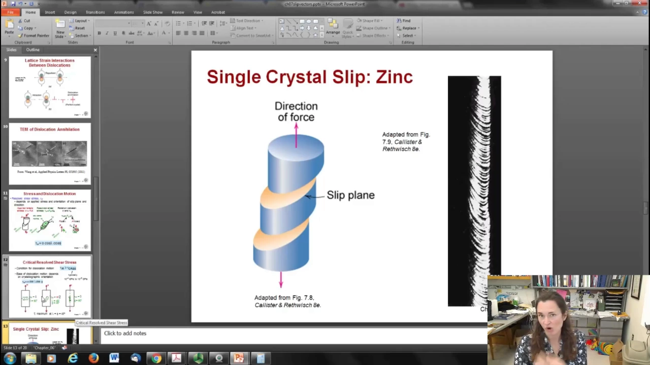
hi today we're going to start a new chapter chapter seven on deformation and strengthening mechanisms and in this chapter we're going to talk about the number why are the number of dislocations present greatest in metals and how are strength and dislocation motion related and why does heating alter strength and other properties of um materials so first of all to address the first question why the number of dislocations is present greatest in Metals in metals the motion of the dislocations is easier because it has that non-directional bonding the metallic type bonding and it has these really close pack directions for the slip um so basically in a metal you have all these ion cores and sort of this free electron C and since the bonding is non-directional it really doesn't matter which direction these Metals slip remember what happens is basically you have atom hopping going on and so if an atom or ion I'm sorry can't hop from one position to another easily then slip won't occur and the dislocation won't move now that's ex helps explain why it's really difficult for that to happen in Ceramics because Ceramics um bond by ionic bonding or calent bonding and remember that in calent bonding it's very directional so if a carbon is bonded to an oxygen for example it wants to be bonded to that oxygen in that direction um and that makes it very difficult for an atom to hop from one position to another because it would have to totally break that Bond um and it it just doesn't slip very easily an ionic in anionic ceramic like sodium chloride or something what would have to happen is that for example this positive ion would have to move over into a negative ion slot or at least pass through it and that it it really doesn't want to do that because then it would be surrounded its nearest neighbors by by positive charges and not negative charges and that's not very favorable okay so what happens is the um dislocation motion occurs when things are plastically deformed plastic deformation occurs by slip when an edge dislocation which is that extra half plane of atoms slides over an adjacent half plane of atoms so here you can kind of see a still frame version of that remember this little symbol right here this little uh T upside down T the red thing here is a symbol for an edge dislocation and it just kind of moves through I have a little movie to show you of that that I'll show you real quick um so here is that dislocation moving through the material it's just a real simple little movie um but that's kind of what you see okay if the dislocations can't move then you can't get plastic deformation and it just doesn't occur um also the diff dislocations are going to be formed generally under stress they're going to happen near existing dislocations or the grain boundaries that's where it's going to start it's going to start at the grain boundary and move through okay so the dislocation is going to move along a slip plane in a certain plane in a slip Direction okay and that'll be the slip direction will be perpendicular to the dislocation line and the slip direction is the same as the burgers vector Direction okay so basically um here's a little cartoon of that you have your um your sheer stress applied here and then it causes the dislocation to move along a certain plane in a direction okay so there's your Edge there's your screw dislocation so which directions are these well your slip planes are going to be the planes on which the easiest slippage occurs and those are going to be the ones with the highest planer densities and large interplaner interplaner spacings and the slip directions those directions of movement are going to be the ones with the highest linear densities and it chooses the highest density Direction because remember you're having atoms hopping from one position to another and the directions with the highest densities are going to be the ones where hopping from one lattice position to another isn't very far okay so here's a little um cartoon of an FCC material okay okay and the slip plane is going to be along the 111 because that's the tightest packed that slip plane here is shown in this sort of orange colored triangle and then here's a 2d view of that so you can see that's a very highly packed Direction so here's a in the um upper back corner b is along the face and so is C it's along the back face and there's DF and that shows you the little cartoon okay so that's the slip plane it's a very high density plane and then the slip Direction are going to be along any one of these directions where it just has to hop to its nearest neighbor um to move across so that'll be sort of a family of directions along AB a or from D to e okay um so there's going to be a total there'll be more multiple slip systems in any given Crystal for FCC that's 12 slip systems and a BCC or a hexagonal close packed it'll be different directions but it's the same concept so in example which of the following is the slip system for a simple cubic structure and why okay so your choices are you know the one uh family of planes along the one One Direction or the one one family of planes along the one0 direction One family of planes along the 01 Direction and so on and so forth okay so the solution is that it's going to be this one right here this one family of planes along the 010 Direction Why okay well if you remember what a simple cubic system looks like it's just a little cube with an atom sitting at each of the corners okay so the tightest highest density plane is going to be along any one of the faces of the cube that's the highest density so I've shown that here in a little cartoon in a 2d view if you cut across the diagonals for example that's not going to be as high density because there's a larger distance in between the corners of the cube than there is along one of the faces so here's a cartoon picture of one of the faces and sort of a a multiple Cube stacking so that's the um family so it's the one family of PLS and then it's going to hop also nearest neighbors it's going to hop from Center to Center this way if it hops along a diagonal that's a further distance and so it's not as tightly packed and so that corresponds to the 010 family of directions okay it's going to hop this way this way even in z um and that'll be the direction chosen okay so what happens is as you move that um line of edge dislocation through you're going to have a region of compression and a region of tension okay the compression is going to be where the lattice is a little more tightly packed than it like to be then it'll feel a compression it'll fill a strain in One Direction and the tension will be the lattice is a little further apart than it would like to be so it's under tension there okay so there's a strain a strain in the lattice around any given dislocation now what happens is as these things move through the material like strains repel one another right so if you've already got a compression it doesn't want to move towards another compression because that would create even more compression and too much stress in the lattice so what happens is uh you get these likes repelling however uh unlikes if a compression sees a tension it wants to move towards that and that'll relieve the stress and hence lower the energy state of the system and when that happens they annihilate so it's kind of a similar idea to positive and negative charges right when they move together the to net charge is zero when a compression and a tension move towards one another the strain goes away and so that what that's what happens and you get a perfect Crystal there um this was actually captured in a little tem mov and here I show you some still frames from the movie from an applied physics letters paper in 2011 remember temm is transmission electron microscopy and so if you stare real hard at this for a little while you can see two Edge dislocations and they've labeled them here for the ease of the eye for one and two and they initially started out about 2. 3 nanometers apart but over time as they took the movie these dislocations got closer and closer together until they annihilated and became a perfect Crystal so we're able to these days not just talk about this in a theoretical way but actually image it and see it happening which is pretty exciting okay um another important concept to understand is the idea of a resolved sheer stress and how that affects the dislocation motion so let's say that you've put your bar or whatever in one of those tinile testing machines and you're giving it a pull okay okay now the thing is your slip Direction um is going to occur along a direction that might not necessarily be aligned with the direction of the force that you're applying to the material okay and so what'll happen is you'll have a force um but then that will not be aligned with the sheer force the sheer Direction uh for the plane okay um so you're going to have to resolve the sheer stress only a portion of that force that you apply Supply will go into causing slip okay so how are those two things related um well basically the you've got the dot product that you're going to take for the direction of the force applied to the direction of the force that is sheared right so you're going to resolve the force applied to the sheer force which is actually what causes the slippage um so there's one dot product there where you're going to take the dotproduct of the applied force to the sheer force Direction and the angle in between those two things is called Lambda okay so that's your slip Direction versus your applied force and then you're going to have to resolve the direction between your um sheer stress and the slip Direction okay and the angle There is five so that's the angle in between your slip um Direction and your applied force all right so your critically resolved sheer stress tal sub R is going to be the sheer stress that you apply from your load machine times the cosine of these two angles um between the direction uh of the applied force and the slip plane and the slip Direction fi and Lambda okay so the condition for a dislocation to move is that your resolve shear stress has to be greater than What's called the critically resolved shear stress okay now the critically resolved sheer stress is typically around 10-4 gigap pascals to 10us 2 gigap pascals okay so here's an example of um a very beautiful example of this someone grew a a single Crystal zinc Rod okay so it's a perfect Crystal and then they applied a a tensile stress to the material but the um slip Direction slip planes were not aligned of course with the direction of the tensil stress and so you see these little directions of the slippage and because it is a beautiful single Crystal then that turned into this kind of gorgeous looking little slip plane stair step thing where it's slipping right along the direction of the sheer stress so that's fun okay let me do a couple example problems here sometimes they call the cosiness of those two angles F and Lambda cosine 5 * cosine Lambda they call it the Schmid Factor and so what they're asking you to do here is to determine the magnitude of the Schmid factor for an FCC single crystal that's oriented with its 10 Direction parallel to the Loading axis so that's the direction that um it wants to slip in now remember we already talked about the FCC family of slip planes and slip directions so for FCC the slip plane is in the 111 it's the 111 Direction that's the most densely packed plane and the slip direction is going to be the one one bar o Direction okay so that's the direction it's going to want to move between the um most tightly packed Direction remember for that you've got your um your your atom here at the corner your atom here at the center and your atom here at the bottom so that's the most tightly packed Direction it's going to want to slip along that direction so it's going to slip along this plane and kind of that way pointing in the direction of Lambda so we need to resolve this okay um for our slip plan slip directions and the direction of our load that's being applied so let's take some dot products okay the force applied to the sheer force will be the dotproduct of the 10 direction that the force is applied in with the slip Direction 1 one bar o okay and when you take that dot product you get 1 Time 1 plus 0 * minus one plus 0 * 0 and that gives you one so that's your dot product and now um that dot product if you set the magn magude of the do product it would be equal to the magnitude of the force time the magnitude of the sheer force time the magnitude of cosine Lambda okay so the magnitude of this 1 Vector is the square root of 1 squ plus 0 squ plus 0 square of course that's one it's a unit vector and then the next is the magnitude of this Vector the one one bar o and that's the square root of 1^ 2 +us 1^ 2 + 0 so that gives you the square root of two and then times cosine Lambda and Lambda cosine Lambda is what we're trying to solve for so cosine Lambda if you set this dot product equal to the magnitude of the dot product and solve for Lambda cosine Lambda you would get cosine Lambda is equal to one over theare < TK of two so that's part of it now the other is the dotproduct of the family of plane with the um applied force so there you're doing the dot product of the One Direction for the loading uh with the one1 family of plane and so when you do that you've got 1 * 1 1 plus 0 * 1 plus 0 * 1 again and you get one so that's the total dot product the magnitude of that dot product would be the magnitude of the force Vector times the magnitude of that area Vector times the cosine of f which is the angle there so yet again the magnitude of the force is one because it's a unit vector and for the 11 one one it's the square root of 1 2 + 1 2 + 1 squ so that gives you the square root of three and then times cosine of five okay and then solving for Co of you get um cosine of is equal to 1 < TK 3 so your Schmid factor is cosine Lambda * cosine 5 which is 1 over < tk3 time 1 over < tk2 and if you um figure out plug that into your calculator you get 048 so that's your Schmid Factor now I want to point out that your um direction for your your value for your slip plane and your slip Direction they don't have to be perpendicular to one another because that's something that a lot of people do kind of think is true but they don't have to sum to 90° those two angles uh if you solve using inverse cosine of Lambda is equal to inverse cosine of 1 over < tk2 then you get Lambda is equal 45 degrees but solving for five you get 54. 7 degrees so those two don't sum to 90 degrees and so you don't have to have your slip plane perpendicular to your slip Direction okay that's not always true even though it is true for example for that simple cubic example that we did a little bit ago the um one family of planes and the o1 slip Direction those are perpendicular to one another so it can happen but it doesn't have to happen if that makes sense okay next example um because I think all this worth is worth repeating consider a single Crystal of silver oriented such that a Ile stress is applied along the o1 direction now if slip occurs in a 111 plane and in a one bar 01 Direction and is initiated at an applied tensile stress of 1.
1 megapascals compute the critically resolved sheer stress okay so um here we have we're going to solve for our cosine Lambda and cosine F again in a very similar way to the way that we did it before so we're going to do the dot product of the o1 Direction with the 111 plane um and then divide that by the magnitudes of those two vectors to get our cosine Lambda and that gives us one over < tk3 and then for five we're going to do the dot products of our o1 Direction with the one bar1 slip Direction and that gives us one over Square < TK of two so our Schmid factor is yet again 1 < tk3 * 1 < tk2 now to compute the critically resoled sheer stress you're going to multiply your stress at which slip is initiated which was given to you in the problem is 1. 1 megap pascals and then you're going to multiply that times your Schmid factor which is 0 48 just like it was before and when you do that you get a critically resolved sheer stress of 0.