Hi,Welcome to module 37. In this module,we are going to look at the controller for theGCDMachine that we aretalking about. So, as I mentioned the notion of the controller is a circuit.
So, this is not some magical thing,it is also going to be a circuit and I already hinted that,it is going to be a state machine. So, it is going to be a circuit that will tell the data path elements on, what is the sequencing of the data. So, we have inputs that are going to be at the subtractor and what not.
So, the subtractor will keep subtracting allthe time. Similarly, the comparatable comparingwill be comparing all the time, but the registers once you lose data, you cannot do anything about them. So, we need to control what values are getting into the registers andthe data path elements had various things.
So, let us look at the controllers picture here, the data path elements are supposed to take select lines at appropriate times and accordingly, the registers will get values, and similarly it is supposed to produce 3 output lines. The data path element will produce a greater than b,a equal to b and a less than b has 3 outputs lines at appropriate times. The data path elements also takes output enable as an input, all these signals are supposed to come from the controller.
Whatever you see here are all going to come from the controllers. So, 1, 2, 3, 4 lines here and this output line here, are all going to come from controller. These three lines are actually input to the controller, clock and resets are something that is common.
So, the controller also takes clock and reset. Besides these, there is also a line called go, that the controller will take and it will generate a signal called done,which is come from the controller. So, we need all these different thingsfor the controller to do.
So, let us see how to go about doing this. So, we are at module 37 andI am going to show you, how to do this. So, in the last class alsowetalked about the notion of,the last weeks lectures, I talked about the notion of state machine.
So, we want to now think in terms of a state machine, what is the state machine,which can actually drive various signals suppose to do. So, remember the canonical model of the state machine, there is something called the input forming logic, something called a state register and something called the output forming logic. But we do not draw the circuit directly, here we always did a state machine and from the state machine, we synthesis the circuit.
So, whatI amgoing to do is,I am going to draw the state machine, which can help us achieve this So, let us think about what are the different kinds of states that we will need. I am going to start with something calledthe initial state. So,I am going to call this state S 0.
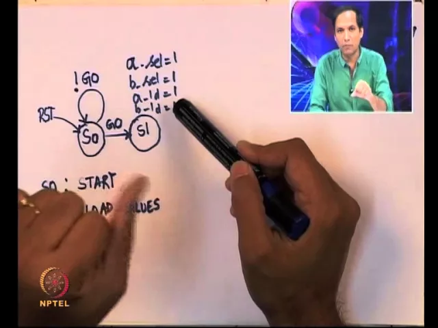
So, the S 0 is supposed to be an initial state and when I reset the machine or when I do a start, the state machine is supposed to come to the reset state. So, I have that and remember, the protocol that we had is, the external world will place the 2 inputs at in 1 and in 2 and then will turn on a signal called go. So, if GO is 1, then I can start processing, which means, the state machine is supposed to tell thedata path to take inputs and soon.
But if GO is not 1, which means, the external world is not ready with the inputs,then the controller is supposed to wait for the GO to become 1. So, the first thingI am going to draw is,I am going to say that, if we do not get go, sothis exclamation means not off, soif GO is not 1, remain in this state itself. However, if we get go, we can start processing the external inputs.
So, what is it supposed to do now this controller, if GO is on, I assume that inputs are going to remainstablefrom the external world. And you got the GO signal from the external world, which means, the first thing that the data path must be doing is, take the values from in 1 and in 2 and it is supposed to put it in the registers a and b. To be able to do that,let us look at the data paths picture.
Let us look at this picture here. So, let us assume that in 1 and in 2 are already ready, we are supposed to put the value of in 1 in a and in 2 in b. How is this possible?
It is possible only if, a selectis 1, b selectis 1, a load is 1 and b load is 1. So, we should have a select,b select, a load, b load; all of them should be 1, sothat in 1 gets copied intothis register and in 2 gets copied into this register. So, this is a select and b select such of these multiplexers to select the appropriate input So, if these are 1,input 1 will appear as input to the a register, input 2 will appear as input to the b register, but that is not enough.
Unless, you have a load equal to 1, the output of a will not copy the input of a register. So, we also need a load and b load to be 1, sothat we can do the copy. So, whatI am going to do is,I am going to have this state called S 1.
So, I will just write down what these different states are supposed to be,S 0is the start state, sothis is the beginning. S 1 is a state whereI am supposed to load the values from the external world. So, S 1 is supposed to be that and when S 1 happens, whatI am supposed to do is,I am going to turn on several control signals.
What are the different control signals? We know that the a selectmust be equal to 1, b select must be equal to 1, then we have a load equal to 1 and b load equal to 1. So, onceI am in this state S 1,I am supposed to turn on all these different values and once these are there, now this, the data path will have the values a and b.
So, let us again go to the data path, let us see what will happen in the next cycle. So, let us say the values a and b are in the registershere. So, in the registers a and b,let us assume that a and b got register.
What is the data path supposed to do now,a and b will be compared, you will get three different outputs here and a and b will automatically appear as inputs to subtractor. After some delay, the subtractor will give some results and they will appear in a minus b and b minus a. So, what we are going to do is, we are going to wait for one cycle, sothat all the values get loaded.
So, remember once you place the control signals, let us say a load and b load equals to 1, only in the next clock cycle, the values of a and b will be available in the register. So, a load and b load both of them are inputs that are going to be sampled by our register and when both of them are 1, the corresponding inputs will be copied, but the output of the register will be available only in the next cycle. So, in this one cycle, whatI am going to do is,I am going to wait for theinputs to come.
So, S 2 is supposed to be a wait state and in this wait state,I am going to wait for inputs to load So, once the inputs are loaded, thenthe data path will have all thecorrect elements, the comparator will have the correct output. So, at this point, the first thingI have to do is, I have to go and look at comparison. So, S 3 issupposed to bea comparison state.
At this point,I am the controller is supposed to So, this is the comparison state. In this comparison state, what we are going to do is, we gave one cycle for the comparator, the comparator would have taken a and b and would have compared it. And the outputs less than, greater than or equal to would have come to the comparator stage So, this is the compare stageand there are now three possibilities from the compare stage.
The three possibilities are that,a is actually greater than b, a is equal to b or a is less than b. So, a is greater than b, a is less than b and a is equal to b, sothese are not the inputs directly So, this is actually given by the condition that, we have an input line called a greater than b, for a less than b, wehave a wire called a less than b and for equal to b, we have a line called aequal to b. So, the meanings of that is in the bracket.
So, for each one of them,I am supposed to do a different thing. So, when a is greater than b, whatI am going to do is,I am going to go to a state called S 4 and what is this statesupposed to do,let us go back and look at the algorithm. If a is greater than b,a equals to a minus b.
Now,let us look at the data path the data path,I have a minus b here. So, I want to take a minus b and put it into a, if I want to do that, then a selectmust be 0 and this load should become 1. So, these two conditions must be there, I should make a select equal to 0 and a load should be 1.
So, that the result a minus b gets register into this one. So, that is whatI am going to do now. In state S 4, whatI am going to do is, sostate S 4,I am going to makea select equal to 0 anda loadequal to 1.
So, that a equals a minus b gets done,I have another state called S 5,in S 5I have to do the reverse. In S 5,I have to do b selectequals to 0 and b load must become 1, the reason why that should happen is, we want b equals b minus a. So, this is for a equals a minus b, sothis is for accomplishing a equals a minus band S 5 is for accomplishing b equals b minus a.
And once these things happened and the other thing that can happen is that, we can have this another state, where everything seems to bedone. So, whether it is greater, whether ais greater than b or b is greater than a, either by whatI am going to do is, sincethe results are coming from the subtractor. So,I am going to go to a new state and in this state,I am going to again wait, sothat all the values get to the proper registers.
So, a should get a minus b or b should get b minus a andfor that, one side turn on the load equal to 1, only in the next cycle, it will be available as output. But once it isavailable as output from the corresponding registers a or b,I am going to be ready to go and compare them once more. So, that is what this state machine is supposed to do.
So, atS 4 and S 5, we know the results of the comparison, atS 6, we let the register take the corresponding values. So, that in the next cycle, they go into the register in S 6, they go to the register and at S 3 is a comparison state,we are ready to compare once more. So, this gives usthe while loop.
The while loop is, while a is not equal to b. So, this part is taking care of while a is not equal to b. but,if a is equal to b; that is the exit condition,I am going to call this state S 7 and in this state S 7 ,so again let me write this now.
S 6 is a wait stateand S 7 is called the done state. So, we are done with all the work. So, S 7 is called the done state, when S 7 equals 1.
When we get to state S 7, what it means is, the register a has the correct value, actually a and b both have the correct value. What I want is, if I go back to the data path, I said will have to take the value of a and copy to the output register. So, that this output register will keep the previous output, even if there is a new computation that is going on, this outputwill be held as long as it is necessary.
So, we turn on output enable, we copy the value of register a into this output register. This will remain at the output, even when the input changes, this will change, only when that next result is available. So, till then it is output register will keep the value.
So, this gives enormous time for the external world to copy output. So, what we are going to do is, in S 7 we are going to say that,output enable at this point from S 7, we will turn on output enable, we will make output enable equal to 1, sothat output gets copied. We will also give this done signal equals 1, because this is the state which tells us that, the while loop has ended, in some sense this is equivalent to printing a.
So, this is the end of the loop,then once this is done,I am ready to go and takenew inputs and at bit state,I am ready to take new inputs,I am ready to take it from S naught. So,I am going to connect this backto S naught. So, that once done signal is ready, it meansI have process the current inputs,I am now ready to take the new set of inputs and what is the protocol for that.
So, once done becomes on, till done becomes on, the external circuitry or external world cannot give new inputs. Because, you are going to be processing here, you are going to be one of these states, suddenly we cannot say go back and look at new inputs and start processing. So, we are in one of these state,we will have to wait till this whole transition gets over, we should come back to S 3 and then from S 3, we come to S 7 at some point of time;that is the end of while loop.
Once,S 7is done, then you come to S naught, at this pointthe externalworld can give new inputs. It can choose not to give any new inputs at all, but if there are new inputs, the external world will keep the new inputs ready and once the new inputs are ready, then it will give a GO signal and only, then the state machine will continue. Otherwise, if the external world does not give a GO signal, it will stay in the state S naughtitself, but when it is in S naught,the output will be the previous computation that you have done.
It will keepplacingthe previous output coming from the whole state machine that will stay on the output, till this GO signal comes. Once, the GO signal comes, the output will still remain as the previous output, till this whole thing processors and generates the new output. So, this is the state machine that we want.
So, you can see, what are all the different things that it is taking? So, reset is an input, GO is an input, then a select,b select, a load and b load are actually outputs. A greater than b, a less than b and a equal to b are actually inputs to the state machine, output enable and done are outputs of the state machine.
So,I am notdrawn this as input slash output and in fact, in any places I have not even drawn, what combination is supposed to take you from one place to other, in many places, they are only implicit. What we are going to assume is that, by default all the outputs are 0, soa select, b select, a load, b load, output enable done, we will assume that, by default all of them are 0,only when they become 1, I have indicated them. And these are the three places, where we need inputs also.
So, a greater than b, a less than b,a equal to b, we need some input to the controller and GO is another place, where we need some input to the controller. The other states are not even processing the inputs to the controller;S 7,S 6,S 5,S 4,S 3,S 2,S 1; all of them do not process inputs to the controller, only S naughtand S 3 are processing inputs to the controller. S naught is a place where you are getting something from the external world;S 3 is the state where you are getting the result of the comparator.
So, this is my over all controller andwhat we essentially have is, we have in some sensethe circuit,we have now go and design a circuit to do this. So, we have the state machine, we have to decide a circuit to do this. What we will do is in a subsequent video, instead of designing a circuit using gates and flip flops and soon, I am going to go ahead a straight away draw the state diagram for this using Verilog.
I am going to write,design this whole thing is Verilog directly. So, in the next set of videos, in the next sequence of videos, what we are going to do is,I am going to design the data path andI am going to design the control path andI am going to writetop level module, which takes the data path and control path together and stitches it up together. So, we will start with that and then we slowly build all the different components; that is supposed to go in together and we will be writing verilog directly for those things.
So, this brings me to the end of module 37 and module 38 onwards, you going to see, how to write verilog for various things and in the process, we will also learn some basic fundamentals of verilog, some of the things thatI am not talked about sofor, will start seeing them in verilog. So, for from 38 onwards, you should keep this picture that I showed inmind and I will also put them up hasPDF, sothat you can see it online. So, keep the picture in mind, when we write the verilog description, you need to have that picture in mind, sothat the whole thing falls in place.
So,I amgoing to show, how to do that from the module 38 onwards. So, this brings me to the end of module 37. Thank you and I will see you in little while.