the electrical system generates and distributes ac and dc power to airplane systems the ac system operates on 115 volt at 400 hertz and consists of two engine driven integrated drive generators one auxiliary power unit generator one ram air turbine generator and one ac external power input the dc system operates on 28 volts and consists of two nickel cadmium batteries and one dc external power input three transformer rectifier units convert ac to dc and one inverter inverts dc to ac four integrated control centers and two secondary power distribution assemblies provide distribution and control of the power
and interface with other systems on the cockpit overhead panel the pilot is able to select or deselect power sources and buses indications are shown on the synoptic page electric and the icus in case of short circuits several circuit breakers prevent overload of the system the integrated drive generators are the main ac and power sources when the engines are running they are mounted on each main engine gearbox a hydro mechanical constant speed drive csd converts variable engine speed into constant generator speed each idg generates constant frequency ac power at 40 kilovolt amp 115 volt 400 hertz
three phase the idg oil system is air cooled the idgs are monitored and controlled by the generator control units gcu's the idg selector knobs are located on the cockpit overhead control panel and must be in the auto position during normal operation when selected to the off position the respective generator line contactor opens and the selected idg will be tripped offline and de-excited a related message on the icast indicates that the idg is offline an amber lead associated with the icast message idg one or two oil illuminates indicating to the pilot which idg must be disconnected
by selecting the knob to the disk position and holding it in this position for one second the idg will mechanically disconnect and the amber led will be off note only authorized maintenance personnel on the ground can reset a disconnected idg for safety the idg features an input shaft shear section and a thermal disconnect operation this will disconnect the idg permanently if there is no manual disconnection the auxiliary power generator is the secondary power source on ground and in abnormal operation in flight it is mounted on the auxiliary power unit with the apu at constant speed
the generator supplies constant frequency ac power the generator provides 40 kilovolt amp 115 volt ac 400 hertz three phase the lubrication system shares the oil cooling system with the apu the apu generator switch on the cockpit overhead panel provides control of the auxiliary generator and must be pushed in during normal automatic operation if the switch is pushed out the auxiliary generator line contactor opens and isolates the apu generator from the ac bus tie a bar illuminates inside the button when it is pushed out the ram air turbine rat provides emergency ac power for the electrical
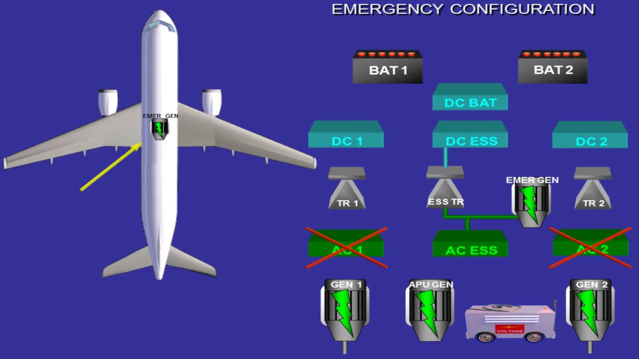
system whenever in flight ac power sources are not powering ac buses and is installed in the right nose section of the aircraft if there is a sudden loss of ac power in flight the ram air turbine is automatically deployed into the airstream the kinetic energy of airflow across the turbine is converted into mechanical power to drive the generator automatic mechanical variable pitch angle of the turbine blades converts variable airflow into a constant generator speed the generator produces 15 kilovolt amp 115 volt ac 400 hertz three phase in flight there is no altitude restriction for ram
air turbine deployment if rammer turbine automatic deployment fails an icas warning message battery discharging illuminates the ram air turbine can then be deployed manually by the ram air turbine lever located on the center pedestal one static inverter provides backup ac power whenever the electrical system is only on battery the inverter is located in the forward ebay ac power is generated by conversion of dc to ac power the input of the inverter is 28 volt dc and the output is 115 volt ac 400 hertz frequency stabilized single phase three transformer rectifier units are the main dc
power sources whenever an ac source powers the aircraft's ac buses tru-1 is located inside the left integrated control center tru-2 is inside the right integrated control center and tru essential is inside the emergency integrated control center dc power is generated by conversion of ac to dc power the input of each tru is 115 volt ac 400 hertz frequency stabilized and the output is 28 volt dc rated at 300 amps of current the tru toggle switches on the cockpit overhead panel provide control of the three transformer unit contactors and must be in auto position during normal
automatic operation if a switch is set to off the respective tru contactor will open two nickel cadmium batteries are the secondary dc power source battery 2 provides apu start and until the ram air turbine is working both batteries power backup dc essential loads in case of total power loss battery 1 is located in the forward ebay and battery 2 in the aft ebay in normal operation any available ac source will provide charging for both batteries the battery switches on the cockpit overhead panel provide control of the battery contactors with the switch in the off position
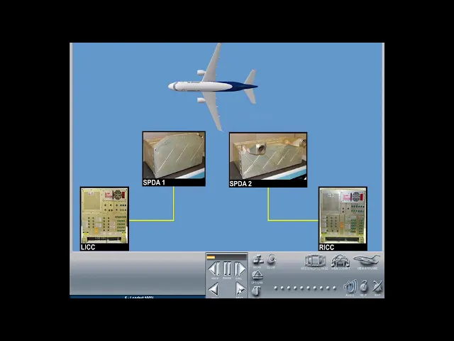
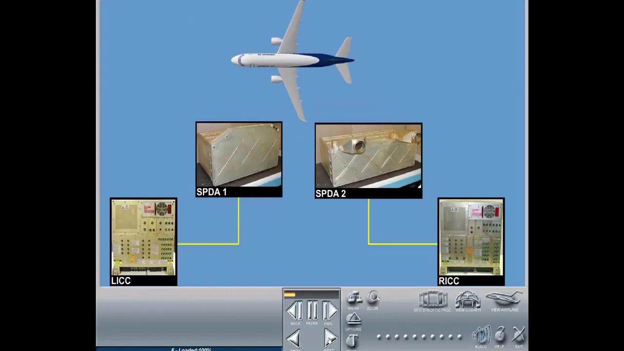
the respective contactor opens and the battery energizes only the hot battery bus with the battery one switch in the on position the battery contactor one will close with the battery 2 switch in the auto position the battery 2 contactor will close except when an apu start is in progress this causes battery contactor 2 to open the integrated control center is an electrical electronic device which provides power distribution and protection for the airplane electrical loads four icc are installed the left and right integrated control centers are located in the middle ebay the emergency integrated control center
is located in the forward ebay the auxiliary integrated control center is located in the aft ebay each icc has incorporated ac and dc buses thermal circuit breakers and line replaceable modules thermal circuit breakers in the icc's are remote circuit breakers they can be monitored via the mcdu in the cockpit if a thermal remote cb trips and ikas advisory message remote cb trip illuminates note thermal remote cbs in the icc can only be reset on ground by maintenance personnel the left integrated control center provides power distribution and protection for ac bus 1 and dc bus 1
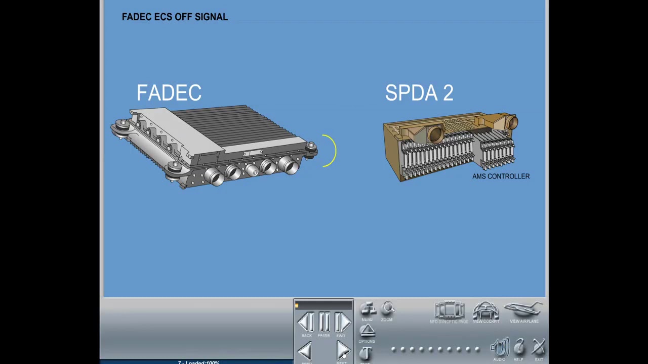
and the ac and dc ground service buses line replaceable modules in the licc are the transformer rectifier unit 1 gcu-1 the external power module and several thermal circuit breakers the right integrated control center provides power distribution and protection for ac bus 2 dc bus 2 and dc essential bus 2. line replaceable modules in the right integrated control center are the transformer rectifier unit 2 generator control unit 2 gcu auxiliary generator control unit acgu and several thermal circuit breakers note the dc essential bus 2 is located in the right integrated control center instead of the emergency
integrated control center this provides dc essential loads in case of damage to the forward ebay where the eicc is located the emergency integrated control center provides power distribution and protection for ac essential bus and dc essential bus 1 and 3. the standby ac bus and the hot battery bus 1 are also integrated into the control center line replaceable modules in the eicc are the essential transformer rectifier unit several thermal circuit breakers the auxiliary integrated control center provides power distribution and protection for apu start bus and hot battery bus 2 and several thermal circuit breakers the
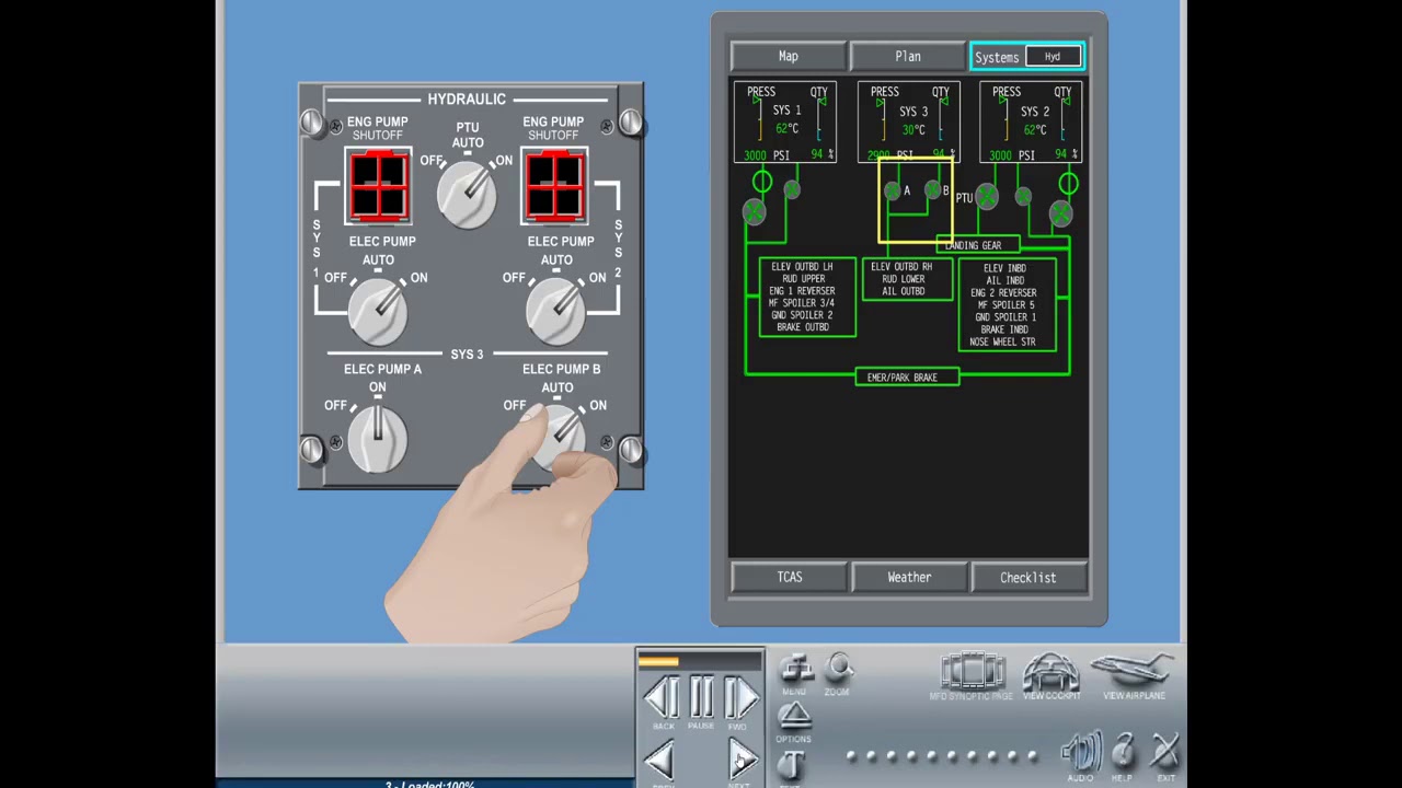
secondary power distribution assembly spda is an electrical loads management and power distribution device it distributes power from the integrated control centers as dictated by logic calculations and specific airplane configurations to several aircraft systems two spdas are installed one in the forward ebay and the second in the mid-ebay each spda has a number of slots where different electronic modules are connected each module has an associated function that provides communication data processing and power distribution electronic remote circuit breakers are located in the spdas they can be monitored via the mcdu in the cockpit an icus advisory message
remote cb trip illuminates if an electronic remote cb is triggered note electronic remote cbs in the spdas can be reset from the mcdu in the cockpit circuit breakers can be either electronic or thermal circuit breakers electronic cbs are located inside the secondary power distribution assemblies and may be reset from the mcdu some thermal cbs are located inside the integrated control centers and cannot be reset in flight vital system cbs such as those for computer reset and power interruption during are located on the circuit breaker panel in the cockpit columns and lines on the circuit breaker
panel are identified through an alphabetical and numeric columns code several units of the electrical system have built-in test capabilities they detect isolate and locate faults that occur in the unit these units are generator control units auxiliary generator control unit external power module and secondary power distribution assemblies the built-in test capability has three levels continuous built-in test fault initiated test and initiated test results of the built-in tests are shown on the icus for crew reaction and sent to the central maintenance computer cmc the normal operation of the electrical system is automatic two independent networks provide complete
segregation for electrical fault isolation the left engine's idg idg-1 normally powers ac bus 1 and the wright engine's idg idg-2 normally powers ac bus 2 and the ac essential bus each ac bus powers a dedicated tru which rectifies ac to dc power supplying dc buses and then dc essential buses if a generating power source fails the electrical system logic provides electrical power to the bus from another source according to the following priority first on-site integrated drive generator second apu generator third gpu if on ground and fourth opposite idg one ac source can supply the entire
electrical system when a total loss of ac power occurs the emergency generator will automatically deploy supplying all essential buses with power source failure thai buses achieve connection between the networks the respective ac bus will be powered by the other ac bus through bus tie contactor btc one or two on the cockpit overhead panel the ac bus ties rotating switch is normally in the auto position and the electrical system controls the bus tie contactors automatically in the one open position bus tie contactor 1 opens and isolates ac bus 1 and in the two open position bus
tie contactor 2 opens and isolates ac bus 2. a btc lockout system provides system protection generator control units the gcu's one and two are lrm line replaceable modules located in the left and right icc integrated control center respectively the gcu's give control protection and distribution of the idg electrical ac power to the ac buses by sending signals to close the respective generator line contactors both glc's 1 and 2 are also located in the left and right icc electric power from an external source may be supplied to the airplane through an ac or dc receptacle ac
ground power is used for flight preparation and maintenance dc ground power can only be used for apu start the ac ground power receptacle is located on the left hand nose section of the aircraft the dc ground power receptacle is located on the left-hand aft section of the aircraft indications are shown on the electric synoptic page releasing the parking brake when ac or dc ground power is connected causes an icus caution message gpu connected to illuminate the ac ground power system accepts 115 volt ac 400 hertz three phase the ground power module epm in the left
integrated control center controls the operation of the system the ground power unit switch on the cockpit overhead panel controls the ground power ac contactor if power quality requirements are satisfied the avail enunciation will illuminate pushing the gpu switch will allow automatic operation for powering with ac ground power if ground power source priority conditions are met the e pack will close and a veil enunciation inside the switch changes to in use and the same change in indication takes place on the exterior ac gpu panel the ground service switch on the exterior ac gpu panel allows activation
of the system from outside the airplane by pushing the exterior ac gpu button the avail indication inside the switch changes into in use to feed the ground service buses the ground service switch located on the forward galley also performs the same function when pushed with ac external power available the ground service buses can be energized the dc ground power system accepts 28 volt dc dedicated system relay logic in the auxiliary integrated control center aicc controls the operation of the system note only the exterior ground power unit switch gpu on the exterior panel controls the ground
power dc contactor epdc if power quality requirements are satisfied the avail enunciation will illuminate the epdc remains open pushing the gpu switch will change the avail enunciation inside the switch to in use if apu start is initiated the apu starter contactor asc will close for use on ground or in flight the cockpit contains two ac electrical power outlets one in the left and one in the right console to allow the flight crew or maintenance personnel to connect their respective laptops or other portable electronic device during normal operation three-phase 115 volt ac 400 hertz power is
provided to the cockpit electrical outlet system by the ac bus 2 and convert it into 110 volt ac 60 hertz the system is switched on and off via the pc outlet control switch when set to on the green outlet leds illuminate to indicate that the corresponding outlet is available the output 110 volt ac 60 hertz is only ready for use when a device is plugged into the outlet unit if the connector is not properly plugged into the electrical outlet the power will not be available it is then necessary to remove the plug and connect it
again whenever the electrical outlet system is activated and for any reason a cabin decompression event occurs the three-phase ac power supply will be interrupted after the pressure is considered normal again the system can be reset through the pc outlet control switch cabin pc power system the optional pc power system is designed to supply passenger seats with a 110 volt 60 hertz ac power for personal electronic devices ped such as laptop computers or other electronic devices the ac bus one supplies power to the converters which then provide ac power to all passenger seat outlets the pc
power system operates only if the electrical system is operating in normal mode in case of loss of any of the electrical generators the system will not operate the pc power ifv panel controls the system and is installed on the control pedestal the galley master switch installed on the flight attendant panel also turns off the system cabin pc power outlet each outlet incorporates a lead that is visible to the passenger and indicates that ac power is available the green color indicates power supply at outlets and the red color indicates power not available the lead is turned
off when the system is not energized the outlet provides power for use only when the plug is correctly connected into the socket and portable electronic device power is enabled cabin crew can monitor the power outlets in use by an outlets-in-use panel installed in the passenger cabin cabin pc power protections a test is performed during power up and shuts down the system if an error is detected the system provides protection against under voltage over voltage over current short circuit and over temperature the system is also turned off automatically in case of cabin decompression pressing the cabin
pc power button on the control panel resets the system