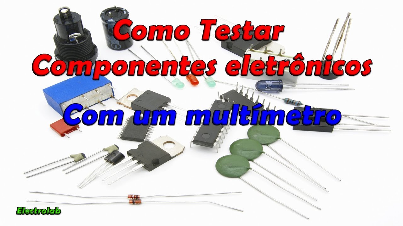
The multimeter is one of the most widely used tools in the fields of electrical engineering, electronics, and automation and it can help us identify most problems. At first, it may seem a bit complex to use, but by the end of this video, you'll understand how all the features of you multimeter work, from the meaning of each symbol to what they do. We'll also see some examples and demonstrations of how each feature can be used, from the most basic measurements to useful features that few people use or know about.
And as a bonus, I'll talk about the categories of multimeters and how to use them safely. So take advantage and subscribe to this channel to receive intelligent content on the technical field. And if you have a friend who needs to learn about multimeters, just click the share button and forward this video to them.
So let's get started! Each Each model of multimeter have different features, but there are measurements and symbols that are common to most instruments. The first symbol is voltage, represented by the uppercase letter "V.
" Note that along with the "V," we have some different symbols. When we have a "V" along with this symbol, it means you have selected the DC voltage scale. Another way to identify DC voltage is by the two letters DC, which stands for "Direct Current.
" DC voltage is the voltage we have in most batteries and power supplies for electronic devices. Here we have a power supply that provides a DC voltage of 24 Vdc. So to make this measurement and check if our power supply is working, we will select the DC voltage scale on our multimeter and connect the red test lead to the unit you want to measure and the black test lead to the terminal labeled "COM," which means "common.
" On our power supply, we have an indication of which is the positive and negative point, so we connect the red test lead to "Positive" and the black test lead to "Negative. " If the voltage is not close to the desired value, something is probably wrong with your power supply. In this case, the measurement is close to the desired value, which shows that this power supply is working properly.
There are other devices that can generate DC voltage, and to identify this, just pay attention to a symbol similar to this or the abbreviation DC. Now in the next measurement, we have the same voltage unit but with the "alternating" symbol. Another way to identify AC voltage is by the two letters "AC", which stands for "Alternating Current".
This is the voltage we find in household outlets. In some places, this voltage can be 110 V or 220 V. When performing these measurements, proceed with extreme caution, as high voltage can cause death and serious injury.
Be careful not to touch the test lead when it is electrified. Now to make the measurement, we will select the AC voltage scale on our multimeter and place the two leads on the measurement outlet. There is a very useful feature in most multimeters where it adjusts the scale automatically, so even if I measure a range of 110 V or 220 V, it will adjust the scale according to the instrument's limit.
Continuing with the voltage unit, some multimeters offer a measurement for more precise signals where the variation will be very small and on the millivolt scale, i. e. , 1V/1000.
This scale is usually used to measure signals from sensors, such as a load cell that varies the signal according to the weight applied to a metal. In this case, this scale has two selections, both "DC" and "AC" voltage. And if you look, the AC voltage symbol is in yellow.
This means that by pressing the "SELECT" button, the millivolt unit measurement changes to AC voltage. Pressing it again will return to DC voltage. Our next feature presented by this symbol is "ohms".
Our next feature presented by this symbol is "ohms. " This is a unit of resistance. Basically, resistance is the difficulty of a material conducting electric current.
If we place the test leads on a copper wire, for example, we will get an almost "zero" resistance. This happens because it is very easy for the current to flow through the copper wire. If we place the test leads on insulating tape, it will indicate a very high resistance value.
In this case, this value indicates that the circuit is open. This is because little or no current can flow through the insulating tape, and that is why we use it. It serves to isolate us from the electricity of the wires and also to prevent an energized wire from touching another and causing a short circuit.
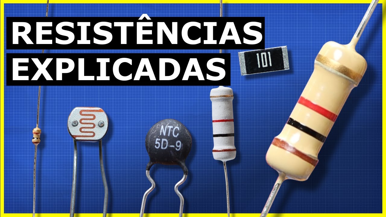
Now we have the resistors. They are devices that help us accurately regulate resistance, and testing them is simple. We set our meter to "ohms" and place the test leads on the terminals.
This resistor, or example, has 100 "ohms," and the measurement is very good. But one important thing to mention is that if you are testing a resistor in a circuit, you may and probably will get a false reading. This happens because there are other paths with lower resistance in the circuit that can provide a false reading, leading you to believe the resistor is damaged.
So whenever possible, you should isolate the resistor you are testing for a reliable measurement. Moving forward on our scale, we have a symbol that means "diode. " This is a diode, and this device simply allows current to pass in only one direction and not the other.
To test this, we place our leads on the diode and get a reading. If we reverse it, we should get no reading, which would be the same as an open circuit. In this case, this diode is working correctly because the voltage can pass in one direction but not in the other.
Now if you get a reading in both directions or no reading in both directions, then your diode is damaged. The next very common feature in multimeters is "continuity. " This is one of the simplest and most useful features in a multimeter.
This feature basically emits a "beep" when continuity is found with low enough resistance. This feature can be used, for example, if we have a roll of wires like this and we want to check if the wire inside is not broken. Just place the test leads on each side of the wire.
If the multimeter emits a "beep," it means the cable is intact and conducting. This feature is also useful for testing a switch contact sensor. For example, let's say we want to know if the sensor is closing or opening the contacts when actuated.
Just place the test leads on the contacts and actuate the sensor. In this case, we have a normally closed sensor emitting a "beep," and when actuated, it opens the contact and stops conducting, turning off the "beep. " These four features: Voltage, "Ohms," Diode, and Continuity are the most common, but there are many more things that multimeters can do.
If you find this video practical and instructive, I would be very happy if you would kindly subscribe to my channel now; it motivates me a lot to make more useful content like this. The next feature we have is capacitance, represented by this symbol. Capacitors are devices that store energy and are widely used in both electrical and electronic applications.
To test them, we select our meter for this function. Here on the display, we have a lowercase "n" and an uppercase "F," meaning nano Faraday. Nano is the scale, and Faraday is the unit of capacitance.
Before testing, know that capacitors are extremely dangerous. There are capacitors that store a large amount of charge and can discharge high voltage. We have polarized and non-polarized capacitors.
Most capacitors have their voltage and capacitance ratings printed in Faradays. Normally, Faraday units are measured on a micro scale. So you will usually have this symbol meaning "micro.
" Here we have the measurement of a capacitor, for example. Our next feature is "hertz," which is the unit of frequency. requency in the case of electricity is the number of times a sine wave oscillates during a period of 1 second.
Depending on where you are in the world, you will see something between 50 Hz and 60 Hz in your outlet. And as always, whenever working with electricity, be extremely careful. So to measure the frequency of the voltage oscillation in our network, what we will do is simply select "hertz" on our multimeter scale and place our leads on the outlet terminals, and we will get something close to 60 Hz with a bit of oscillation.
Now in addition to frequency in "Hz," many multimeters also work with a unit called "Duty Cycle," indicated by a percentage sign. By pressing the "SELECT" button, I change the unit. "Duty Cycle" is known as duty cycle and indicates the percentage of time the current is "positive" compared to the total time.
In an AC current, the common duty cycle is "50% on" and "50% off". In this measurement, the measured value shows a duty cycle of 50% and the other 50% of the time "no work. " Another less common feature, but present in multimeters, is "hFe," also known as "Beta" or "DC current gain," and this function is used to measure the current gain of NPN or PNP transistors.
In this case, we have to use an adapter and place it in this input. Here we have the indications of the types of transistors and the terminals. Now we take our diode and need to find out if it is PNP or NPN.
If you don't know what type your transistor is, you need to identify it through the transistor code and look up information in the manual or datasheet. There we will have various information, including the identification of the collector, emitter, and base terminals. Now just connect the transistor correctly to the adapter, and we have the indication of the current gain value characteristic of this transistor.
This is a somewhat more specialized and complicated feature, but it is widely used by those who work with electronics, and it is good to know it is available for use. Another common feature is the "temperature probe. " This feature is used to measure the temperature on any desired surface.
This measurement can be done in two units: "Celsius" or "Fahrenheit. " Here we have to connect a sensor that usually comes with your multimeter. In this example, we have the indication of the surface temperature measurement of a lit lamp.
Finally, we come to the feature of current measurement. Most meters have a separate input for measuring higher currents, because depending on the measurement limit, an appropriate fuse will be used internally for your protection and that of the multimeter. Let's start with the milliamp scale.
These signals are widely used in industrial instrumentation where the standard signal of analog instruments and sensors is 0 to 20 mA. Note that the connector is separate and has an indication of a fuse with a maximum protection limit of 400 mA. If you exceed this value, the fuse will blow, and you will need to open the multimeter to replace the fuse.
For your safety and that of the multimeter, always use an appropriate fuse for the measurement. In any current measurement, you will have the option to measure DC current or AC current according to the symbols next to the measurement. To do this, just press the "SELECT" button to switch the type of current.
All current measurements using the test leads require opening the circuit and performing the measurement in "series" with the conductor. It doesn't hurt to remind you of the importance of caution with electricity and paying close attention to safety measures when doing this. Higher current measurements also have their limitations described at the connector input.
Here we cannot exceed "10 A" for more than "10 seconds. " If you exceed the limit of your meter, a specific internal fuse for this connector will blow, and you will need to replace it by disassembling the multimeter to access the fuse. It doesn't hurt to remind you: "Use the correctly specified fuse" for your safety and that of your multimeter.
As you can see, the multimeter has many applications. I would like to know from you watching this video: "In which area do you use the multimeter the most? " Industrial, residential, electronics, automotive, or general use at home?
Comment here to let me know. These are the most common features in a multimeter, but there are a few more things we need to learn to fully understand everything in a meter. For example, in many meters, by pressing the "Range" button, you can move the decimal place to have whole or more precise measurement values.
In this case, we are measuring the voltage in an outlet, but by moving the point, we can have a whole value of the voltage or a more precise value with a decimal place. Note that by pressing the "Range" button, the "auto" function of autoscale disappears because we are determining the scale manually. Another interesting feature is the "REL.
" The "REL" button on a multimeter is an abbreviation for "relative" and is used to set a relative reference measurement. This function allows you to zero the current reading of the multimeter, and from that point, all future measurements will be shown as "differences" relative to this reference measurement. For example, here we have a 12 V power supply.
If I measure the 12 V power supply and press the "REL" button, the multimeter will zero and record this 12 V value as a reference in its memory and signal that the zero indication is not the real zero. Now by measuring the 24 V power supply with this function activated, according to the display, instead of having the total value of the power supply, which would be 24 V, we will only have the difference in value between one power supply and another. This is very useful when measuring voltage drops at different points in a circuit.
Now if you want to record a value even without performing the measurement, you can use the "Hold" function. This will freeze the value on the multimeter's screen even if there is no longer a measurement. Note that when the value is frozen, the function appears on the screen to indicate that this value is fixed on the screen.
Pressing the button again, the multimeter returns to indicating the real measurement value, which in this case is zero, because I am not connecting the test leads to the power. Now finally, the last feature of our multimeter that few people know exists is the "LED" function to illuminate the display. When your multimeter indicates this symbol, it means it has this feature.
Just press for a few seconds and that's it. Even in a dark environment, I can clearly see the values on my multimeter. Now before finishing this video, I want to talk about the most important thing in a multimeter: Safety.
Starting with the test leads, always use the certified leads according to your multimeter and your type of work. On these test leads, we have some useful indications: CAT category, CAT III, 1000 V, 20 A. The CAT measurement category defines the test lead's resistance to transient voltage surges.
These categories are defined by the IEC: "International Electrotechnical Commission. " They indicate the environment in which the equipment can be used safely. There are four categories, and each is suitable for a specific type of use.
In the case of this 1000 V and 20 A test lead, these are the maximum voltage and currents it supports. Now on our multimeter, note that we have some specifications about i ts safety category. The CAT IV, 600 V maximum category means you can use the multimeter to measure up to 600 V in a Category IV environment, such as power distribution panels and general power inputs of a residence, for example.
Anyway, here is a warning: Do not exceed your instrument's specified limit as it can cause fatal accidents. If you were already aware of safety when using your multimeter before watching this video, comment here, I want to know. I hope this contributes to fewer electrical accidents.
Now the last thing I will mention in this video is the "True RMS" feature. Some currents can often have waves that distort readings and cause up to a 40% error rate in multimeter readings. "True RMS" multimeters can provide accurate measurements of effective voltage and current values, even in distorted waveforms.
This feature is crucial for many modern applications where accuracy and reliability are essential. If you've made it this far in this video, it means you've learned more than 90% of all the features that exist in most multimeters. And now do you think I deserve a like?
Comment "#multimeterfinal" just to l et me know that you watched this video until the end. Also, if you want to always receive intelligent content on YouTube, subscribe to my channel here. See you in the next video.