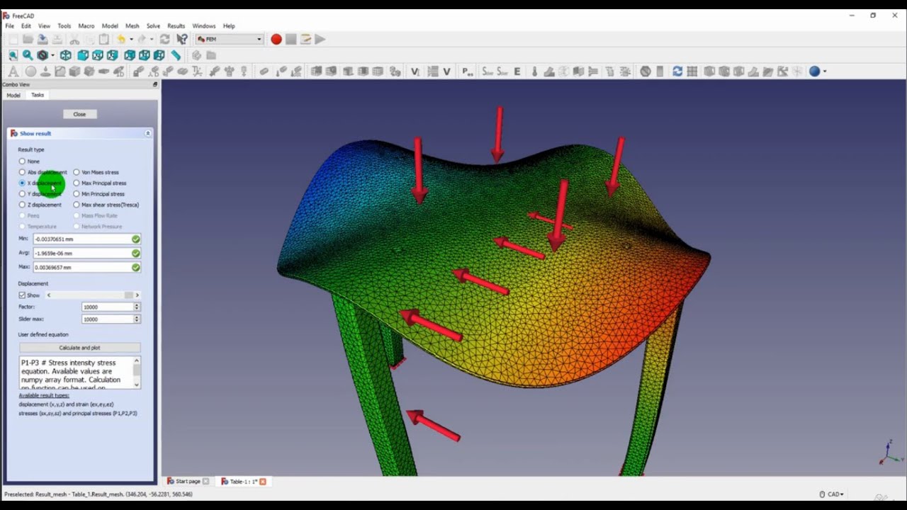
hello and welcome to my next tutorial about repo max this time i will show you how to analyze chain links subjected to tension let's define unit system first and import the geometry in step file format and the geometry is already imported you can see that we use symmetry again and the geometry is prepared in free cad here's a single piece of the model that was prepared first and then the two pieces were assembled using add-on module for freecad and this model was exported to pre-bombings now let's create a mesh i will specify meshing parameters for
both parts and the global maximum element size will be 2 millimeters and i will leave the rest with default settings and now i will also specify mesh refinements since that's a contact problem and we want local refinement around the contact area for more accurate results so let's specify size of 0.3 millimeters and i will apply this mesh refinement to this and this edge and this one right here as well and now i can create another mesh refinement with the same setting and this will be applied to equivalent edges but for this part we have to
create separate refinement since those are separate parts so let's add this edge and this one and this one right here let's confirm this and let's create the mesh for both parts at once the mesh is already generated so we can proceed to the analysis setup as always let's define material first and this will be still just like in previous videos i will specify young's modulus and poisson's ratio and i will also define section and this will be a single section for both parts since they use the same material and now i have to define contact
so let's create a surface interaction first this will be service behavior with default heart contact setting and now i could define contact pairs manually select the appropriate faces but in us version of repo mx there's a very convenient tool you can see this here search contact pairs or also here search contact pairs this tool automatically searches for contact pairs within the specified distance and angle and we can switch between tie constraints and contact pairs so this in this case i will switch to contact pairs and we can also group by parts and it will automatically
apply and the interaction that we defined previously and i can also specify if i want a mesh adjustment or not in this case i will leave i will leave this disabled so let's search for the contact pairs as you can see the software found appropriate contact pair in this case there's a situation where we could easily pick those surfaces manually but there are often cases where there are many potential contact pairs and the surfaces are hard to pick because they are covered by other parts so we will have to hide some parts and pick the
surfaces define the surfaces first then use them for the contact pairs definition it would take a while and this tool is very convenient and notice that it's very well implemented so let's confirm this and now we have contact per defined so i just have to define a new step this will be static step with default settings and now i will define boundary conditions i will specify displacement boundary condition this will be symmetry since as you can see the part is symmetric let's disable mesh for now and i will pick those two faces and constrain them
in the z direction and since there's a symmetry direction and now we'll apply another displacement boundary condition for these two faces and this will be in y direction and finally and the last boundary condition to fix this face in x direction now we have all the boundary conditions defined and i can define load this will be a surface traction i will apply this to the face right here and it will be in x direction and the value is minus 200 newtons let's confirm this and now the whole model is defined we have the contact pairs
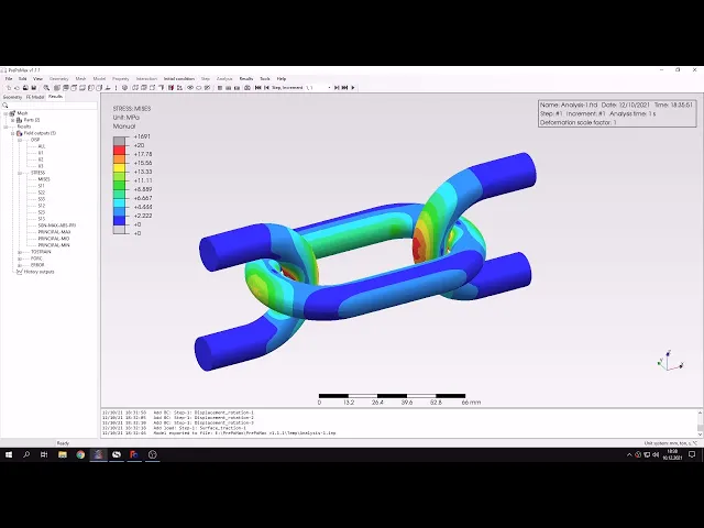
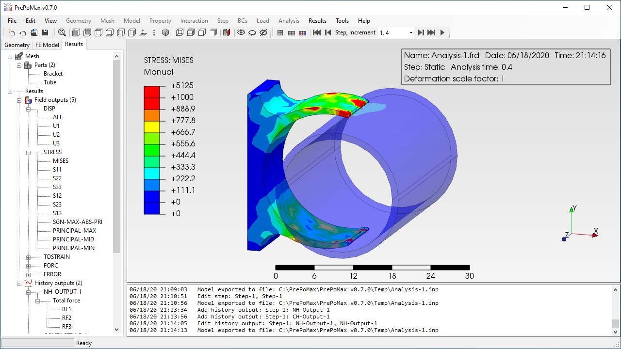
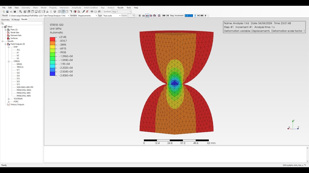
boundary conditions and loads so i can submit the analysis and of course it might take a while since contact is using those analysis but we should have the results available soon the results are available now so let's check them here you can see in the full missed stress plot but let's switch to stress in x direction to compare this with analytical solution uh before we check the stress in this area let's switch to the sheet where i have the analytical solution and here you can see that the value that we expect is around 3 000
megapascals and this solution is based on hertz contact problem assuming two cylinders with perpendicular axis this is just an assumption since the actual chain lengths are curved and they are not just straight cylinders but so i had to make an assumption and you will see that the results are in quite good agreement other approaches used for uh chain links are lame problem it's sometimes suggested in various books or curved beam theory if you want to check the stress away from the contact area but in this case we are interested in the contacts area stresses so
let's use the solution from a hairs contact problem that we have here let's compare this with the value that we obtained from the analysis and as you can see and there's a very good agreement at least for the point of contact of course we could refine the mesh around this area and apply further local refinement and you'll get even closer to the unicode solution but we are already very close so uh it's really good for a such approximation let's now uh change the view i will switch to view without displaying mesh i will also change
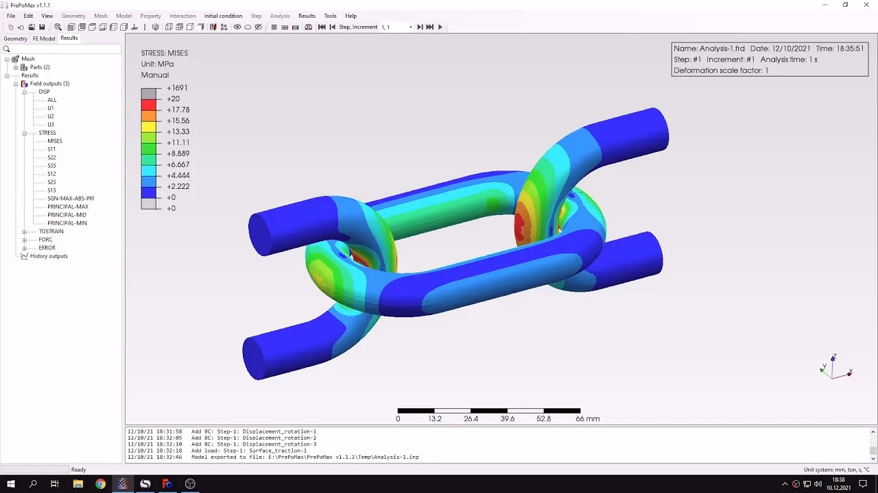
to from stress i want to show you something regarding the visualization itself we want to just use some tricks to make it look better let's now adjust the legend i will change the maximum and minimum to limit type to manual and i will specify a maximum value of 20 megapascals it's already there so i don't just have to apply it um and now we'll be able we will be able to see the stresses apart away from the area of contact um because here they were all focused in this area and now we have better view
of stresses in other regions let's do one more thing i will use the transformation in x y and z axis and now we will see how the whole model looks like without just looking at the symmetric part and that's the whole uh piece that you actually wanted to analyze it does just for the visualization purpose that's pretty much it for this preparedness tutorial thank you very much for your attention as always feel free to ask any questions and suggest topics for future tutorials see you in the next video and have a nice day