As a society we'd become used to computer problems of one kind or another just as we become used to computers we're so used to them in fact the few of us stopped to think of the extent to which they now play a role in our everyday lives a role that shows every sign of growing even bigger if you look at sort of the process of the technological Revolution that we're all in it's a process of taking very Centralized things and making them very Democratic if you will very individualized making them affordable by individuals for a
small collection of tasks if you will sort of from the passenger train to the Volkswagen I mean you think back just a couple hundred years and people could barely even travel between states let alone get information from one place to another instantaneously that is power that is so powerful having instantaneous Information transfer that's the biggest breakthrough of all of it hey you know how to code or at least how to speak a programming language to interact with the computer nowadays all you have to do is swipe right so the purpose of this video is to
lay a good foundation to step by step understand really what's going on inside a computer and I mean like physically we're going to demystify at least the Major functions that happen and how it interacts with what we call software we will eventually be making specific references to HVAC equipment but none of what we're talking about is specific to only that industry so if you're not in that field this should still be a good watch [Music] imagine you have a light bulb in a circuit with two switches in series we know that in order for the
light bulb to Light up we need to complete the circuit so the current can flow through it so that means that in this case we need to close this switch and this switch we can make a little table so that we can map out what will happen in different situations with both switches off the light doesn't shine with switch a on but B off it still doesn't shine the same goes for when a is off and B is on then finally with both switches on the light does shine now what if instead we Connect the
two switches in parallel now the circuit from the light to the battery will be complete when we close either switch a or switch B right and if we close both not much changes in the light keeps shining the same kind of table can be made for this Arrangement defining what will happen in each scenario and we call this a truth table there's no gray area here we can logically map out the output or whether the light shines given a specific input The position of the switches la logic refers to the process where you outline what
the outcome should be given a particular set of inputs and think about inputs as just different scenarios that can come up so I can tell you if this happens and this happens then what should be the result so how do we go from this very basic manual logic To something like a computer well what if instead of having to flip switches by hand we replace these manual switches with relays now we can use an electric signal to drive the relays open or close or off and on and you can see that this matches our first
scenario where in order for the light to turn on both relays had to be on you can still think of pressing these buttons as a way for me to change the inputs and thus get different outputs But instead of a person pressing these buttons they could just be electric signals coming from somewhere else ultimately if you look at what's going on in the wires going to the coils in the relays there's either 5 volts when I push the button or zero volts when I don't and those are two different conditions or signals when I push
the button or even when I don't push the button I'm providing the system with a little bit of information or data this Is literally the smallest amount of data we consider in Computing terms and it's so small that we actually call it that we call it a bit again there's only two options on or off also referred to as high or low or in this case 5 volts or 0 volts to simplify all this with computers we arbitrarily refer to the two states as one or zero so you can think of this circuit as a
type of gate that only allows signals to be passed through when certain Conditions are met and for this reason this is called a logic gate specifically this is an and gate and here's a symbol and truth table for it we also covered or Gates where either A or B input being A1 results in an output of one logic gates are the building blocks for all traditional modern computers and we'll soon see why but even back in the 40s when the first real computers were being developed designers chose a Different component to build logic gates the
vacuum tube vacuum tubes work on a similar overall Principle as relays as we can have one circuit that controls another circuit but how it does it is completely different this glass vacuum enclosure houses two middle strips called electrodes one of the electrodes is heated by a filament when voltage is applied across these electrodes electrons sort of boil off and jump off the heated electrode in a process called Thermionic emission since the other electrode is positively charged the electrons are happy to cross the Gap and flow across the circuit in this configuration the vacuum tube acts
as a diode since electrons can only Flow In This One Direction but we can add one more electrode called a grid to control the flow and the way we do this is by changing how positively or negatively charged the greatest if it's negatively charged or negatively Biased then the electrons leaving the heated cathode will sort of hit a roadblock remember like charges repel and Opposites Attract enough negative charge in the grid stops all current flow in the primary circuit on the flip side when the grid is positively charged even just a little bit the electrons
leaving the cathode don't really mind and they keep traveling across the Gap re-establishing current flow how they thought of this I have no idea but it's Super clever and to get some hands-on experience I built this little circuit this is called an inverter as it takes one bit of information and flips it to be the opposite that's why when I push the button the light turns off here's the truth table for it and honestly it's as simple as it gets what I realized though is that even just making this simple circuit with this vacuum tube
I found it very hard to work with for a few reasons so the question is why then Did they overwhelmingly choose to use these over relays in the 40s 50s and 60s to answer this I hooked up the vacuum tube to an oscilloscope mapping the control signal to the grid compared to the flow across the primary circuit and you can see that the signals follow each other really closely if I zoom in there's essentially no lag each one of these squares represent one microsecond the vacuum tube responds extremely quickly now when I take the same
Measurement across just one of these relays it initially looks the same it's a fairly quick response but when I zoom in you can see a big difference there's a big lag here between the time I pass the control signal to closer relay to when the primary circuit actually closes it's something like 10 milliseconds so comparing the two the vacuum tube is many many times faster than a relay because it has no moving Parts like the relay does for this reason the otherwise Inconvenient vacuum tube took over resulting in some truly massive computers that took up
entire rooms or buildings and consumed an enormous amount of electricity to perform just a few calculations and really the problem was that we were reaching the limit of how big we could build them the operating principle of the vacuum tube worked just fine but we needed something more practical enter the transistor It was the invention of transistors that basically have allowed us to achieve the computing power that we have so far because of the fact that we're able to introduce these components that used to be very large now we can miniaturize those components to be
able to build smaller circuitry with very very tiny transistors embedded in them at the heart of any transistor is silicon an atom which has four valence Electrons when these atoms come together the electrons like to pair up and create a tightly knit structure because everything is so neat and organized the electrons are sort of locked down and this material acts as an insulator if we try to pass current through it it just won't work as there's nowhere for the electrons to flow they're happy saying inner structure but some really smart people figured out that we
can change This property by simply mixing silicon with other elements in a process called doping so the first element is phosphorus phosphorus has five valence electrons so when we mix a few of these atoms into the Silicon structure they'll fit right in but they'll have an extra free electron which is somewhat able to move and wander around now if we apply a charge to this phosphorus dope silicon structure the Free electrons will be attracted to the positive side of the battery making room for more free electrons to come from the battery and we get current
flow through the material we refer to this specific material as n-type silicon the second element is boron which has three valence electrons much like phosphorus this atom has no problem taking its place in a structure but this time instead of having an extra electron we have the opposite well we consider an Electron hole or a place where electrons could and would like to flow into this material called p-type silicon will also conduct electricity since now we have a place for electrons to flow and fill in from nearby atoms creating more electron holes in a chain
reaction with these two materials what we really care about are the free electrons and the electron holes these two are considered charge carriers that allow Chargers to flow through each material And things really get interesting when you put these two materials together immediately what happens is some of the free electrons will jump over and fill in some electron holes here meaning those charge carriers are gone basically now this middle area becomes kind of like an insulating barrier because it's completely depleted from any charge carriers now when we apply a voltage differential across both materials the
result depends On which direction we apply the charge if the negative side of the battery is connected to the inside then a bunch of the electrons will flow into this material making it negatively charged at the same time electrons will leave the P side to go into the battery making that P side positively charged this so-called bipolar Junction creates a big imbalance and if the battery voltage is high enough eventually the electrons from the inside will be so Attracted to the P side that they will start jumping across this barrier wanting to fill in the
electron holes this creates a constant flow in this direction so what happens then if we flip the battery in the opposite direction well some free electrons from the n-type material rush to the battery's positive side and some electrons from the negative battery terminal enter the P material to fill in some electron holes And that's it there'll be no flow across the junction this is exactly how a diode Works using an n and p Junction to only allow current to flow in One Direction and from here we just have to add one more chunk of n
material to make a transistor so this is our control circuit and this is a primary circuit that will be controlled when the control circuit is on electrons are already flowing across this Junction right so when There's a voltage across the primary circuit some of these electrons that have already crossed this Junction are close enough to this positively charged region to jump this other Junction and establish a flow through the transistor if we make this middle P region even smaller then most of the electrons will choose to go this way so now it only takes a
little bit of current to control the transistor and as soon as we stop the flow across the Control circuit the primary circuit will also stop flowing because there's no way for the electrons to be able to cross these two Junctions without help we call the middle of a transistor the base and confusingly enough due to the long established idea of conventional flow which is opposite to electron flow we call this side the emitter and this side The Collector [Music] here's a schematic for an and gate made Out of transistors we can consider the two bases
of the transistor are input bits and this LED light indicates if the output is on or off in order for the current to flow we need to turn on both of these transistors by providing a voltage to their base the nice thing is we can actually build this circuit to look nearly identical to the schematic and test it out when I power the first transistor at the Base nothing happens but as soon as I power the second one ha the light turns on meaning our output is now a 1 or on what's nice as it
is that this circuit looks just like this schematic it's much more practical to model this on a prototyping breadboard so here's the same thing on breadboard but I have added two buttons one for each input and these blue LED lights indicate when I'm pressing the button we can make any logic gate out of Transistors here's an or gate for example imagine just how big of a breakthrough transistors were when first introduced just to make this simple logic gate their size and power consumption was much much smaller compared to vacuum tubes while still retaining their lightning
speed so at this point you might be wondering how are these logic gates useful I don't really get it and to be honest that's how I was but now that we've made it all The way to the transistor I can finally show you how we can put these logic gates together to perform useful operations like say adding two numbers we all know how to add numbers right we use the decimal system to add say 12 plus 9. since 2 plus 9 is 11 we take the 1 and the remaining one carries over to the next
row which combined with the other one gives us two and we get 21. so we're all used to this decimal or Base 10 system but in order to be efficient computers have to use a different system the binary system this system uses the number two as its base raised to some power so for example 2 to the power of 0 is 1 2 to the power of one is two two squared is four two cubed is eight and so on number gets twice as large as we keep increasing the exponent the great thing about binary
is we can represent any possible number by combining these Powers of two together so if we just want the number four we can point to this position here and that's it but if we wanted six we combine the four and the two four plus two and we get six or a bigger number like 13 we combine eight four and one and we get 13. so how do we express 13 then with the system well with computers we just make a distinction between the powers that we want to use versus the powers that we Don't use
and to do this we use a string of ones and zeros once showing the spots we do want to use kind of turning these numbers on and away and zeros basically omitting these numbers or turning them off so to represent 13 we need a 1 in the first position a zero in the second a one and a third a one in the fourth and a zero on the fifth each one of these positions is a bit since it carries one bit of information be it a One or a zero and each of these bits is
operated by a transistor A1 is represented when voltage passes through the transistor and a0 when it does not so now we're expressing 13 as a 5-bit number using five positions so to speak technically we only need four bits to express this number as this zero here is not really helping us but it's not uncommon to have this happen we could even express 13 as an 8-bit number or even higher and we just have more zeros More bits just allow us to express higher and higher numbers so yeah they may seem like a waste when representing
smaller numbers for practice let's look at four bit strings and strings is just a name for these bits in a row we can count all the way up to 15 using 4 bits expressed in binary here's one two three four five six seven eight nine ten eleven twelve thirteen fourteen and Fifteen by Definitely kind of weird at first but then you start to realize how efficient it is after all we only need four little bits of information driven by four transistors to express up to 16 numbers in this case including the number zero don't forget
zero is one of the options so now that we understand how numbers are expressed let's go back to our original example and add 12 plus 9 using binary to express 12 we combine the eight and the four giving us the four Bit binary string one one zero zero and here's the number nine we combine eight and one giving us one zero zero one we can add these together by putting them on top of each other just like we did with normal addition so here zero plus one equals one zero plus zero is zero one plus
zero is one and here one plus one is of course we know it's two but there's no such thing as two in binary so you can think of this as getting 10 on your base 10 Edition you have to carry over one spot and you get this this is the number 21 and notice we had to use five positions or five bits because with four bits we could only count to 15. so we did this all manually to show the process but now the question is how do we design a computer that can compute this
for us let's take a look at this first operation adding two bits from the same row together we already showed how this Works so we can make a truth table showing all the possible combinations zero plus zero is zero one plus zero is one zero plus one is one and finally one plus one is zero so if you remember this truth table looks very similar to an or gate but this last situation is a little different we want the output to be zero when both our inputs are one and this actually constitutes what's called an
exclusive or gate or xor gate our third major type of logic gate there are Different ways of making an xor gate in this example uses five transistors you can see that it starts out with the same layout as an or gate but all this extra circuitry is designed to restrict the path to ground coming out of this or gate when both A and B inputs are on and so our truth table matches exactly what we need it to do to add two bits together of course I've gone ahead and assembled the circuit and you can
see that when Either input is on the output is also on but when both inputs are on the output turns off so we are in essence adding two bits together the problem with this setup though is that it doesn't account for our remainder like when I add one plus one together the output is zero but we should have a way of knowing that there's an extra bit that should carry over to the next bit column and with that in mind we can add some more circuits like an and gate to indicate That the sum has
resulted in a carry bit shown here as this yellow LED light now I want to make a circuit that can add two 4-bit numbers together like when we added 12 and 9. and to do this I would need a bunch of logic gates it actually gets a little more complicated when you're spanning across multiple bits and I did the math I would need 64 transistors to make the logic gates for this circuit we could do that but it'd honestly be kind of a pain so instead we Can use these little guys called integrated circuits or
ICS integrated circuits can house all kinds of things in a smaller platform for example this one contains four different and Gates within it or this one here has four different or Gates so this allows us to minimize the number of components and wiring for all kinds of circuits I just need five of these chips to make the 4-bit adder circuit and still it takes quite a bit of wiring to connect this All together to be honest I made a few mistakes building this so there was lots of troubleshooting involved I also had some silly issues
with some wires just not making good enough contact with the breadboard which was a bit of a headache but in the end I finally got it to work and I felt this was definitely deserving of two thumbs up I'm using these dip switches to input our two separate 4-bit numbers into this Adder so here I have one plus one equals two then three plus Three which equals six or like in our example I can input 12 plus 9 12 is again one one zero zero so I set the switches that way the nine is one
zero zero one and after I get that input we can see that the result is one zero one zero one which is correct that's 21. I think this is a good demonstration of how we go from transistors to logic gates to something useful imagine having to make this with vacuum tubes 64 vacuum tubes to add some Little Numbers we've Definitely come a long way but this is still a behemoth of a device and it's still not super useful I mean who wants to be inputting binary and reading the results as LED lights so that leads
us to The Next Step how do we go beyond just logic and make these devices work for us one of the key aspects of any computer is its ability to easily communicate useful information our little 4-bit Adder is not very good At this but take a look at this the world's first calculator it could display the results using these nice numerical displays these are called Nixie tubes and personally I think they're really neat we've got 10 digits 0 through 9 all formed and wired like a filament kind of but unlike a light bulb filament it's
not the filament itself that glows but the Neon gas right next to it due to some crazy science of the electrons flowing from the filament to This mesh so to make this work we just have to apply voltage from the mesh to one of the digit filaments each one has a different pin at the bottom unfortunately these take a lot of voltage like 85 volts DC just to turn on my DC power supply doesn't even go that high so I use this variable Transformer in the bridge rectifier we made in the last video to get
higher voltage DC if you haven't seen that video I've attached the link in the description With this much power you'd have to use a bunch of relays just to drive the digits which I mocked up so you can see it in action mine only counts up to five but you get the idea it's interesting and mechanical as all this is it takes up a lot of room and consumes a lot of energy which seems to be the trend associated with other technology so the next best thing for this kind of application are segmented displace like
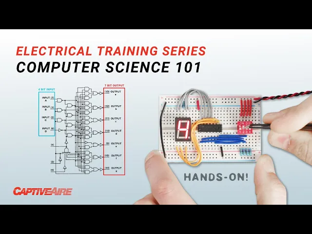
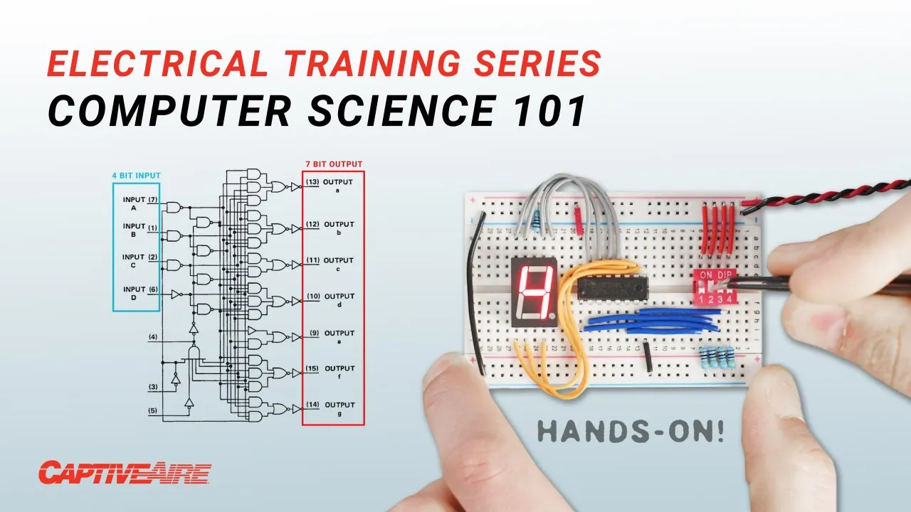
this led one these are much lower power and Connecting power through each pin results in each of the seven segments to light up we can use an integrated circuit like this one that will sort of translate a 4-bit signal to light up the individual segments and build the correct digit here's the translation chart with the 4-bit input marked as a string of else and H's for low and high and here are the outputs for each segment of the display what kind of blew my mind is that They're achieving all this using logic gates and some
pretty complex wiring this is not really an easy conversion from a 4-bit input to a 7-bit output and there are techniques to figure out what kind of logic gates and circuits you need given specific inputs and outputs using what's called Boolean logic which is kind of like logic algebra and these things called karno Maps which allow you to visualize sort of what you need now as this place get more complex there are Better ways to achieve these kinds of conversions than just using Straight logic like for example in this LCD display this display is receiving
information from this Arduino board but everything that's going into the display is fed by these four wires let's take a look at the signals for the letters a b c d for the letter A we get this cable transmitting a high voltage while the rest remain at zero volts in binary this is the string zero zero zero one we can Use this conversion or lookup table provided by the manufacturer to see what that means so zero zero zero one puts us in this row and for the letter A we need to be in this column
which is 0 1 0 0. honestly I can't quite see this signal in the scope and I suspect it's just too quick but that information is there somewhere just for fun if you woke up this morning wondering what the 4-bit signal for captive air looks like here you go this Is for you what this display is doing is much more advanced than the seven segment display first off we're taking what's really an 8-bit input signal made up of two 4-bit chunks each 4-bit chunk can be arranged into 16 possible combinations and 16 by 16 means
we have up to 256 possible combinations in total then we have to translate each combination into a symbol comprised of 40 dots each dot then has to turn on or off to create a complete visual Representation of each character or symbol doing this using nothing but straight logic would be crazy so instead this display uses memory I remember every fact I'm exposed to Sir Commander what is the capacity of your memory 800 quadrillion bits memory comes in two general flavors long term and short term I don't know how data's memory works but this is uses
long-term memory embedded or programmed at the factory to translate the 8-Bit signals into the Correct output the signal we provide to the display is nothing more than an address used to point toward the data for each one of these 40 pixels the data for each address is permanently stored as a 40-bit string so how do we do this how do we sort data permanently there are actually quite a few ways but the most common for these applications involves the use of a special transistor called a floating gate mosfet let me just give You the basics
booster allows for current to flow or not flow just like with our transistor from earlier and this is controlled by this circuit here in this normal condition if we apply a low voltage across both circuits the electrons flow we can read this flow resulting in a logic high or one however when we provide higher voltages across the terminals we can cause electrons to become trapped here in the floating gate Potentially forever now when we try to flow electricity across the transistor at a normal voltage the electrons stuck in the floating gate reduce or even prevent
the flow across the transistor we can again read this flow and determine it's now too low resulting in a logic zero if we wanted to reset the transistor we could apply specifically High voltages across both circuits attracting and releasing these electrons back into the body so in essence by Controlling the presence of electrons in this layer we can allow the transistor to flow or block this flow permanently or until we decide to change this memory that uses these floating Gates is called flash memory like this little SD card that can hold 128 gigabytes of flash
memory just for reference there are 8 billion bits in a gigabyte which means in this little SD card we can store over 40 billion of the characters we've been talking about and how we do it we'll get To in a second but first let's look at the other type of memory short-term memory let's say you're adding these four numbers maybe the computer can only handle adding two numbers at a time right like with our Adder so it will add these two then it will remember this number load it add it to the next then remember
that number load it add it to the next and so on and so forth we could in theory hold these numbers in long-term memory but that would be Painfully slow with flash memory it can take a few milliseconds to access and read or write data which in Computing terms is quite an eternity but with short-term memory it's a nearly instantaneous process so let's see how it works so far we've only been talking about logic gates in a linear fashion but interesting things happen when you feed the output of a logic gate back into its input
take this or gate at the most basic level if we wrap its output Back to one of its inputs and provide a 1 to its other input its output will stay as a 1 even after I let go of that other input and it will stay like this until I disconnect all power to it we can take this concept further to build something like this data latch say we have one bit of data coming in turning on and off and just kind of doing its thing but what if I want to save that data now
capturing that one bit of information in its current state I can hit this button to enable the mechanism to capture that slice in time and there you go now we've captured or in Computing terms latched this as A1 maybe then the data keeps coming and going but the latch still remembers what it was at the time that we told it to remember but now I wanted to remember again when the input is zero because I'm not pressing the button you can see now that it does remember it store that moment in Time as a zero
so this data latch uses logic gates to store data as either a0 or a one and one bit might not be so useful but we can scale this up for example we can put eight of these together in a row making what's called a data register that stores 8 Bits which is also the definition of one byte this is one way to do it but generally the best way to scale memory up is to use a grid configuration like this then in order to access a specific bit We need much less wiring but how do
we access each bit individually well we use addresses again to pinpoint where the data is in the x and y axis and when voltage is applied across these two wires we can use an and gate to access the specific memory latch in only that latch this way of packaging memory into a grid is how we're able to condense so much memory into such small spaces like the SD card Now that we understand basic logic operations and how to store and access memory we can start getting into the job of a microprocessor which is basically like
the brains of a computer when we're talking about a microprocessor a microcontroller it's a device that has several different components so it has certain memory components where it stores data and it also has processing units such as adders that allow the microprocessor to perform Arithmetic operations so when a programmer is writing a computer program the different components within the microcontroller are the ones responsible for executing those instructions so we discussed a very simple component which is a half adder but from that component you can create adders for multiple digits any type of arithmetic operation can
be derived from those very simple components so that's how a microprocessor does the legwork of Processing we have all these billions of transistors that are used to build the logic gates such as the and gate that we discussed and then the logic goes from very high level mathematical components into lower level recursive actions of using these component is to make the calculations that it needs in order to execute any given program thankfully when we program computers to perform certain tasks we're not just writing ones and zeros here's a program Written by a person in the
language called C this program is designed to print or display on screen even numbers that exist from 1 to 50. first we tell the computer that we only want to look at whole numbers represented by this I then we tell it to look at numbers less than or equal to 50. finally we tell it to take those numbers and if after dividing them by 2 the remainder equals zero meaning it was an even number to begin with then we go ahead and print That number on the screen and that's it of course without prior knowledge
of coding this looks like gibberish but what's it like for programmers generally I tell people well a computer program is not that different from human language in the sense that there is a structure that you are expected to follow there are ways in which you refer to different things so things have names or in the case of a computer program there are certain addresses that you refer to so It's a very structured and methodical way to manipulate data it's not as flexible as human language in the sense that you can't be vague about what you
want to do you have to specifically use the predefined structure of the language in order to achieve what you're trying to do now that we've written this code in C there are a couple of translations that need to happen in order for it to be ready for the microprocessor First a computer program translates or compiles the C code into what's called Assembly Language this is now a very specific set of step-by-step instructions for each portion of the code designed to work with specific processors for example load this value to this specific memory register or compare
two values then depending on what happens maybe jump to this location on the code then keep going and so on yeah it's basically a set of Instructions that are allowed each processor has you know however many dozens or hundreds of instructions that it's allowed to do and then operators for all of those and it's essentially another language you can write all your code in assembly if you wanted to in fact we had to do that in college to get an understanding of how it all worked but no one really does that that's just like uh
for for learning the final step Before feeding these instructions to the microprocessor is to translate them again this time finally into just ones and zeros this process links each step to the appropriate binary string that will direct the processor to execute that instruction for example the term load register might be one one one zero the register location might be one zero one zero and this value might be zero zero one zero now there may be times when programmers do work directly with This low level code and looking at just ones and zeros it's really easy
to get confused and make mistakes so a common translation from binary is hexadecimal or hex hex breaks down any binary string into four bit chunks we know that each 4-bit chunk can be represented in decimal as a number from 0 to 15. but hex is even simpler than that and that it only uses one character per bit chunk so once we get to what would be 10 we start instead using letters for example Here's a 16-bit binary string converted to hex this is much easier to read and we can do the same thing to our
machine code but this is just for people when feeding the code to the computer ultimately it's going in as binary because transistors just want to know if they should be on or off and that's what the processor wants basic Specific Instructions so when you're when you're trying to understand how a computer works and someone explains to you what Logic gates are and what they do you start thinking well a lot of these operations are very basic right like anyone anyone can add to Binary digits together but whenever you start thinking about the Computing capabilities that
we have today then you start realizing the complexity that these devices can handle just because of the fact that they are able to perform so many operations I'm currently at any given time now a lot of these operations are driven By a clock so every time there's a clock tick that tells the existing components that they need to perform in action so you get a signal that says okay process the next bit process the next bit process the next byte you can make a simple clock circuit out of transistors capacitors and resistors this one's pretty
slow you can also use an integrated circuit designed for this application and in both scenarios the speed of the clock depends on this Resistor and capacitor combination so we can speed up this clock easily and the signal looks like this but how fast can we go the frequency is very very high so you get millions and millions of operations every second so when we're talking about one megahertz is one million operations per second one million cycles per second and we can keep going on one gigahertz is one billion cycles per second so the the speed
at which these transactions are Occurring is Extreme high so that's how computers are able to process data and information so quickly that it's almost seamless from our perspective so for half a century now the trick to making computer hardware better and better has been miniaturization which allows for more transistors to fit into smaller packages consuming less power while running at faster speeds Moore's Law predicts that every two years the number of transistors on a microchip will Double we've actually been following that since the 70s and the result is that today this consumer desktop processor can
perform about 400 billion operations per second and yet it's smaller than one vacuum tube from the earliest computers and with this the real question becomes what do we do with all this power so everything here is stuff I've worked on for captive air in some way shape or form This right here was kind of my my big project that I've had for basically the whole time I've been here when I first joined the company we didn't have our own circuit boards really we were using um I can't remember what it's called it's a really annoying
technology to use and there's like this pre-built off-the-shelf thing that you have to program and it's got these weird pins that you plug in it's just a pain and we Really just want to replace all that and make it significantly cheaper and easier to customize and make it exactly how we want a really big captive bear thing is if you see something and it's not quite what you want get rid of it and we'll do it ourselves and we'll do it better and I love that mentality and it seems like we always keep doing that
and it has never served us wrong so this is the ECP 103 board which is For the hood ventilation control we can have a kitchen Hood a very long kitchen hood that has multiple like cooking elements and in this long Hood you can have multiple exhaust fans and temperatures associated with each section of the hood and say one side just just way hotter than the other why would you want to turn the fan on over here when you're maybe not even cooking so we can we can control the fans Individually based on their temperature needs
so it's super hot over here we're gonna have this fan going you know full speed this fan maybe low speed just to help make up for some of it if it's drifting but and then temperature kicks up over here later then we spin this one faster so it's all individual control per what's needed where that's just one one example of the many things this board can handle and I think one of the Hardest parts about embedded software or embedded design is knowing what you can do and knowing what to do with it like I go
I go home and I try to think of hobby projects to do with things like this and it's it's not always easy there's a lot of use cases for things like this but they're not always practical the hard part is making something that is useful that people will actually need or want to buy And that's that's something like this you need something to control your hoods efficiently and properly you can have an on off switch sure but you're not going to have safety features or Energy Efficiency or anything like that if you're just on off
switch it's such a cool concept and the same thing's happening for the MUA board and HVAC in general whether it's Hood packages Advanced Refrigeration systems make up air units or you name it all these HVAC Technologies benefit greatly from the use of smart controls and one thing they all have in common is the fact that they interact with the real physical world so let's look at some sensors commonly used in these applications the simplest one I could find was this float switch this is used to detect a certain level of water in something like a
condensate drain pan when water is present at a high enough Level the float moves up and it mechanically opens the switch so the output of this sensor is really simple it's just one bit the circuit is either on or off depending on the water level a computer would have no problem handling this signal just as it is we can let the program know that when the circuit outputs A1 there's no water and when it outputs a zero there's water there are quite a few other sensors that have the same kind of binary output even if
Internally their design is more complex here we have this pretty fancy sensor used to detect oil in the compressor regardless of the high-tech infrared technology this sensor uses in the end the output is either a zero or a one that's it but what about something like temperature I mean we can't always just have a switch that's on and off oftentimes we want to know the actual temperature value in degrees Fahrenheit so here's a temperature sensor which Uses a thermistor which is just like a resistor whose resistance changes greatly with temperature at room temperature the resistance
across this thermistor is around 10 000 ohms but when I heat it up the resistance goes way down now the trick is how do we convert this resistance to a temperature value and going into this I thought well that's simple you just have some sort of conversion chart to convert the resistance to a degrees value and you're Done right so sort of in my reasoning I skipped one major point this analog signal that is resistance you know the computer doesn't know how to read that like at all natural resistance in a thermistor is about as
far away as you can get from ones and zeros so what we need to do is convert the signal using an analog to a digital converter or ADC into a binary string for the computer to read There are a few ways to do this but they all use a component called a Comparator this device Compares two input voltages and if this voltage is higher than this one it outputs a logic 1. otherwise it outputs a zero so the first thing we do is we apply a set steady voltage across a thermistor since the thermistor is
changing resistance due to temperature we know that the output voltage would also change with it the higher the resistance the lower the voltage we can sample this voltage let's say it was 3.4 volts and feed it into The top leg of say four comparators okay now let's say we knew that the range of voltage we're looking to measure is between 5 and 2 volts and I'm just making this up we can take 5 volts and apply it to this bottom reference leg of the first comparator then we can continue this circuit and add a resistor
here meaning this one's only getting 4 volts then add another resistor so this one only gets 3 volts and another so this one gets two and then send this all To ground now each comparator is comparing our 3.4 volt input to a different voltage so this top one would output a zero because the reference is higher than the input voltage same with this one but this comparator would output A1 and so with this last one because 3.4 volts is higher than both of these reference voltages so as a voltage from the thermistor Loop changes so
does the binary output of this analog to digital converter now we finally have a Binary number whose value we understand and can reference to to a lookup table to convert to a temperature now this ADC is very crude and not too precise if for example the voltage coming in was 2.8 volts all we would know is that it's between two and three volts but we could scale this up and add more comparators to get more and more granular readings the ADC used in this board is actually integrated into the microcontroller and it's a 10-bit ADC
which means it can Measure voltages in up to 1024 sort of little slices so you could have a lookup table with 1023 values for temperature corresponding to the resistance of the thermistor but after talking to Alex I realized that's not what we do and the reason why we don't do that is that that would take up a lot of memory instead the processor is loaded with about 100 values or 10 percentish so if with some luck the output of the ADC is one of the values that we do store like the number 530 then we
just take that temperature and we're done but if the output of the ADC Falls between two values like if it's 520 what will happen is the processor will look at the two closest temperature values and perform some simple linear math to approximate the correct temperature the nice thing is the region we care most about Precision which is sort of 50 to 80 degrees happens to also be the region in this thermosers temperature curve in which The change in temperature compared to resistance is also the most linear so that means that this approximation is most accurate
in the area that we care about the most and that's not a coincidence I am so proud of the software that I've written for this it has been so fine-tuned and it's just amazing how much we have fit on this tiny little chip this tiny little chip only has 64 kilobytes of space total for code and that is That's like nothing that's like what NASA had when they went to the moon the first time but the reason we chose something like this is because it's so easy clean and cheap you have such full control and
so little overhead that anything you want to happen you know you're you're the one causing it to happen for better for worse so we use many input devices to gather data but it's still important to be efficient if you remember from our psychometrics Video we can measure any two parameters of moist air to calculate any other property so instead of directly measuring things like dew point wet bulb temperature or vapor pressure we calculate these values using just temperature relative humidity and the corresponding equations and this is extremely useful for units that refrigerate or temper the
air so thus far we've only really been talking about the local operation of these controllers But there's a lot more we can do with them something that we can do and that we generally do is connect these controllers to a building management system in this case we have a Gateway which we will call a scada up here that's collecting data through the modbus protocol and that all goes that all happens through this cable it's collecting all the data that this Controller is using and then it's sending it through a cellular connection to our servers and
to basically a database that can be accessed by a website to interpret that information and display it in a meaningful manner so that engineers and end users can make decisions and monitor the operation of the system I want to talk about this modbus protocol that Juan mentioned you know what is a protocol what does that mean And for this demonstration I have this whole Dusty keyboard from like 2003 the standard keyboard uses around 104 keys so if we take apart this wire you might expect to see 104 tiny individual wires but that's not the case
at all there's only four wires and in fact only two of them carry data that's because this keyboard is communicating through a protocol called Universal serial bus or USB if we actually look at the signals going to the computer it's these really Fast pulses that in the end just make zeros and ones to represent different keystrokes sent out as little packets of information every fraction of a second the USB protocol dictates how this information is packaged and communicated and Protocols are extremely useful in many applications like HVAC with analog signals I can only get like
temperature or any type of readings but it won't tell me what that controller is trying to do I can't tell anything about its Logic I can't tell anything about what its set points are now if I have a network connection the physical connection is obviously much more simple because of the fact that I don't need wires for every single type of signal that I'm trying to monitor so it's much much easier and then I can not only get data about the sensor inputs to that controller I can also get data about the decisions that that
controller is making and why those decisions are Actually happening so I'm allowed to increase the level of complexity of that communication by having a protocol that dictates how that exchange occurs the modbus protocol Works based on a master and auxiliary system in this scenario the dcv board acts like the master and it can control in theory an unlimited number of auxiliary devices like variable frequency drives the devices only communicate when the master requests something and the auxiliary Devices are always listening for these commands and reacting to them accordingly since we can daisy chain several devices
onto the same wiring this exchange happens with only one auxiliary device at a time which makes modbus relatively slow there are faster Protocols of course but modbus has good benefits you could run really long cable links if you have something on the whole other side of the building you can just run a ethernet cords which is just so Nice since the modbus protocol is a defined standard we can translate it and repackage it into any other standard protocol using what are called gateways these devices simply convert the signals from one protocol to another which is
useful if we want our modbus devices to interact with other building management systems using a different protocol like bacnet we also have to repackage data for things like Wireless Communications the board we use for this is called Scada which stands for supervisory control and data acquisition that's exactly what it does it basically harvests data from all of our products and puts it all on one server for everybody to view it's crazy how much you can see on cast link it's it's insane to me every time I go on there that you can just see so
much in so many places all over and they have control too from cast link they can go press a button on there and Turn fans on somewhere on the other side of the country there is no guarantee that the equipment will operate as it was intended to once you pass it on to the end user if at some point settings are changed or something was not set up properly right after the building was turned over then there's a risk that those units will potentially operate 24 7 operate at times where there's no one in the
building so a building management system Takes away those risks it gives you visibility of what your different components are doing and making sure that they are not only operating efficiently but also operating only at the times that they need to be working so it all comes down to energy and comfort in a lot of cases like you you're able to look at the different sensor data the different operational statistics of the equipment just to make sure that everything is working as Intended at all times you start becoming very very intimately familiar with the equipment that
you're monitoring so you have all these data sets all this data from equipment that's all over the world experiencing all these different environmental conditions and serving this broad range of spaces and you know how it's operating you know how it's responding to different types of changes so having all that information allows us To better model what a unit should be doing at any time so we can take all that data and we can potentially Implement machine learning algorithms to detect faults or any other type of situation before it actually creates a problem in a space
or we can create a model of a unit to try to perform reinforcement learning algorithms for future fine-tuning it's going to become much much easier and more practical for more applications to make use of of Machine learning and AI in order to implement Solutions you know if you have a team of Engineers that are constantly trying to optimize the operation of HVAC or any type of machine for that matter the fact that we have all this data and the fact that we're able to interpret separate this data accurately and the fact that we have so
much computing power to manipulate that data to will eventually allow us to just automate some of the actions that are taken and Have our Engineers focus on different types of things so everything that's repetitive will eventually be phased out from those types of environments and the activities that I'm leading within our teams internally are focused a lot on incorporating more of those types of algorithms into our day-to-day so yeah I think you know it's just very interesting very exciting I read a survey in Scientific American in the early 70s and what this survey had done
Was it measured the efficiency of locomotion for various species of things on the planet Birds fish dogs and it ranked them and man sort of came in with a rather unimpressive showing about a third of the way down the list but someone at that magazine had the insight to test the efficiency of man riding a bicycle and man riding a bicycle was twice as good as the Condor all the way off the end of the list and it really Illustrated man's ability as a tool maker to Fashion a tool to amplify an inherent ability that
he has and that's really exactly what we feel we're doing we're really sort of Blazing the trails for the 21st century bicycle but to amplify a slightly different inherent ability that man has the ability of a certain part of intelligence right now we're at the mechanical part of intelligence where one of these devices can free a person From many of the drudgeries of life and allow really humans to do what they do best which is to work on the conceptual level to work on the creative level foreign