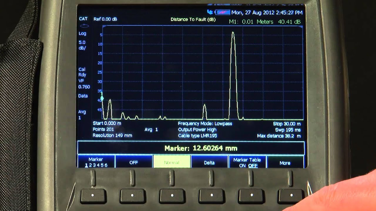
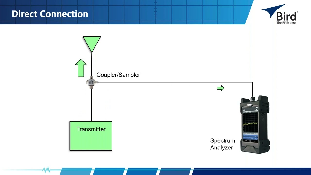
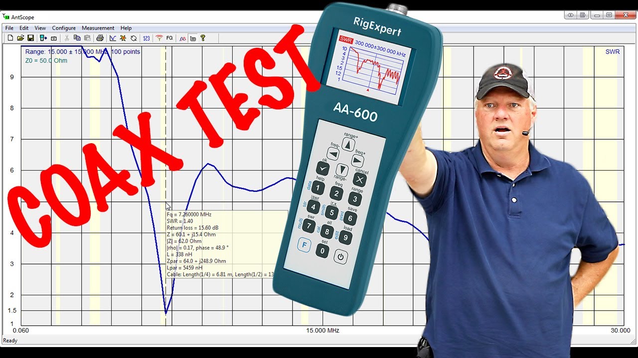
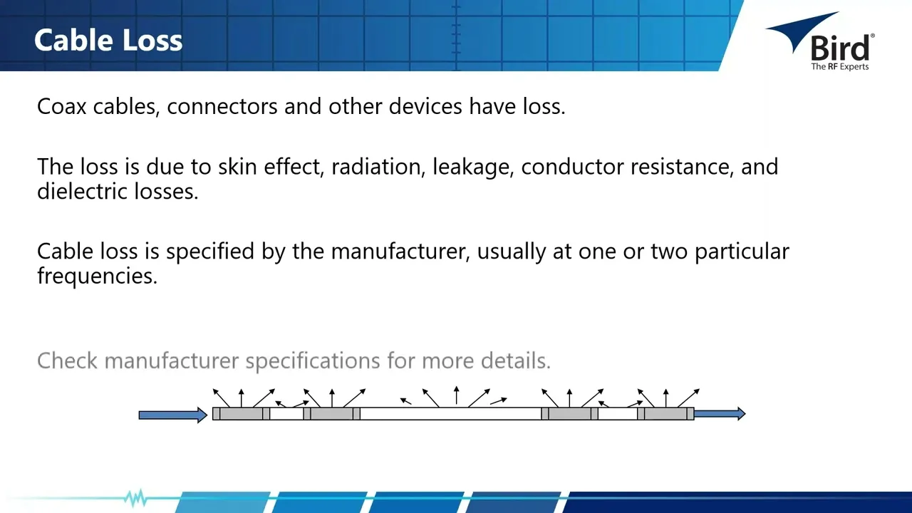
today we're going to talk about cable and antenna measurement Basics so for the agenda today and we're going to call it segment one our topics are be solving the problem cable and antenna key measurements RF basics for antenna system troubleshooting key features of a cable and antenna analyzer importance of regular calibration why and how we do it and then for next week I'll give you a little teaser it's going to be all about DTF or distance default measurements we'll talk about the setup for distance default what you need to know to make a distance default measurement how to interpret a sweep once you've taken it and then I'll throw in a few tips and a few few best practices continuing on we'll talk about some things that are changing over the last 20 plus years the use of radio frequency energy as a communication medium has exploded digitally encoded signals Wi-Fi digital FM radio GPS 34 and 5G equipment is causing the radio spectrum to become congested frequency reuse in the broadcast television and radio bands has opened up more possibilities unlicensed products from Toys to home networking systems has exploded and all of these systems have put more pressure on the RF technician to be able to spot potential interference problems maintain systems that operate to expected standards avoid causing interference to other services and radio frequency systems employ feed lines that are often not easily accessible some consist of hundreds of feet of coaxial feed lines clamped to a tower held together with adapters and connectors attached to the antenna hundreds of feet in the air add in abnormalities such as bullet holes animal remains ice and snow and incorrect installation how do we fix this by using a cable and antenna analyzer to perform key measurements the key measurements that we'll discuss today are measure match and this is a measurement to determine if there is a problem with your system system impedance versus frequency is plotted on the display you get your results back in vswr or return loss we have distance default or DTF this pinpoints the location of the problem distance versus frequency is is plotted on the display and you also get your results in vswr or return loss and finally we have cable loss and this is to determine how much power is being lost within the line or in individual components the measurement may be called insertion loss cable or attenuation and this is a manufacturer's specification the benefits of line and antenna sweeping are tests it tests the overall Integrity of an antenna system installation and we can verify that antenna system components meet manufacturer design specification and verify that antenna system meets the design engineer design specifications pinpoint the location of antenna system problems prior to usage and then finally we confirm the system integration and antenna performance you may ask yourself why do I need a cable and antenna analyzer well we use it for system commissioning system commissioning antenna system commissioning is a process whereby faults and potential Faults Are eliminated before they compromise the system prior to the system being put into use it is structured and methodical but also thorough with the goal of having 100% system uptime for Effective Communications we use it to troubleshoot existing antenna systems when there is a problem you can quickly read the system and determine where the problem is and finally we use it for preventive maintenance perform sweeps compare the sweeps save during commissioning to see where changes may have occurred and fixed potential problems before they take the system down completely all components in a feed line System including the antenna must be matched in their characteristic impedance can anybody tell me what is the character characteristic impedance we are interested in we all want to make sure that all our components are matched to 50 ohms impedance matching measure match or simply match it all refers to the same measurement it's how well each of the components within a system are matched to the rest of the components this is also measured in vswr or return loss I we'll talk a little bit about coaxial cable impedance feed lines are designed for a specific impedance and as we learned from the previous Slide the impedance we're interested in is 50 ohms impedance is defined as the total passive opposition to the signal it is a function of the diameters of the center conductor to the outer conductor and the DI electric constant of the insulating material between them changes in any of these Dimensions will change the impedance of the feed line understanding what causes impedance changes is halfway to solving feed system problems one of the fundamental laws of physics States when load resistance or impedance is equal to the source internal resistance or impedance that maximum power will be developed in the load what that says in other words is when everything in your system is matched when you key up your radio all the power will get out to the antenna and I mentioned coaxial cable impedance is a complex function of the ratio of the diameters of the conductors if the diameter ratio changes the impedance of the cable will change and the power transfer changes also these change from things such as a dent a kink deformation too sharp of a Bend radius Etc if the transmission line and the load impedances are not the same meaning they are mismatched power is reflected from the load in the form of a wave traveling back to the source waves moving in the other direction towards the load they interact resulting in a series of standing waves along the length of the transmission line a short or open will cause 100% of the power to be reflected and we measure this in vswr or return loss in DB so here we have an example of our transmission line and we have keyed up our radio and we have our forward power traveling down the line and it hits some sort of a mismatch it could be a dent too sharp of a Bend radius or anything and when it hits that mismatch we get a little better reflected power and you can think of a garden hose that has no obstructions in the water flowing flawlessly no Reflections but what happens when the hose is kinked or the transmission line is shorted we have a restriction of flow and all our power doesn't get out vswr versus return loss what is it what does it mean I'll show you a little chart here a perfect vswr would be 1. 0 to one that's a perfect match a perfect return loss value is negative Infinity both of these values mean that 100% of the power is delivered to our antenna it's not possible because every component will have a certain amount of loss if we have a vswr of 1. 43 to one that uh coincides with A-5 DB return loss this also means that very little reflective power is present 96.
8% of the power is delivered to the antenna and only a little more than 3% of the power gets reflected back and that's not too bad if we have a vswr of 1. 5 to1 - 13. 989 6% of the power gets delivered to the antenna only 4% gets reflected back and most antennas will be speced either at for between a certain frequency band at either 1.
5 to1 vswr or14 BB return loss those are the common goals is to have everything um be at that value now if our visir or vswr Rises a little bit we're up at 2. 0 to one notice our return loss drops to negative 9. 54 that means about 89% of the power is delivered to the antenna and we have about 11% reflected back we're starting to run into a little problem area it's not real severe but it's you can see that it's starting it's going to start giving us issues and if you rise up to 10.
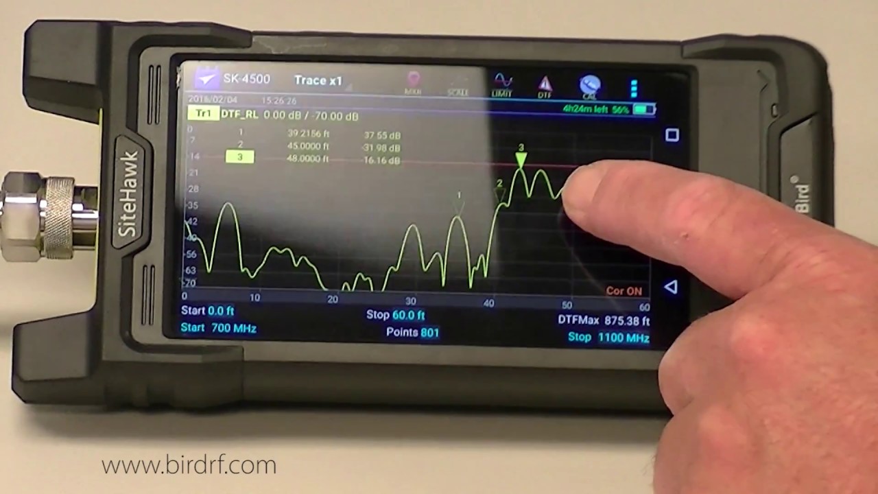
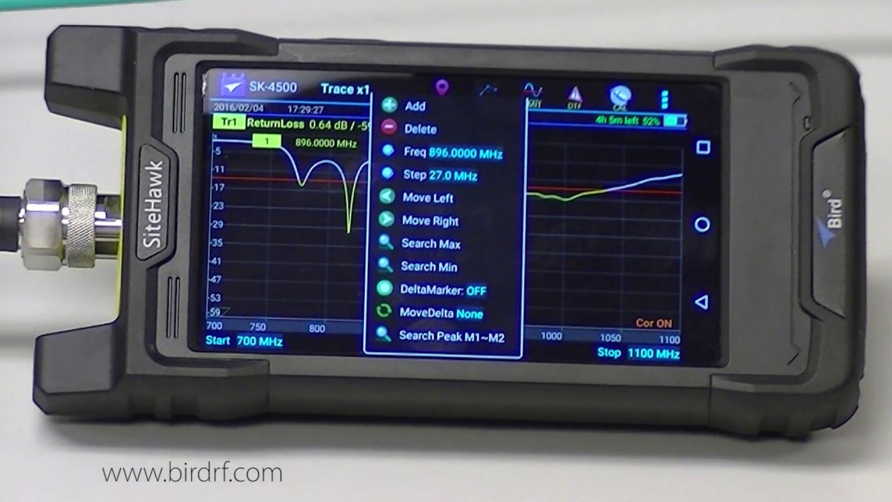
0 to one vswr or negative 1. 74 DB on the return loss scale this is a very poor match only 33% of the power gets delivered to the antenna and the rest is being reflected back think about it if you have a 10,000 kilowatt a 10 kilowatt transmitter and only 33% of the power is delivered to the antenna that means only about 6700 of watts is getting reflected back to your transmitter and you're going to have some issues so this is what it looks like or a relationship between vswr versus return loss what are some of the things that cause an impedance mismatch well there's a lot of things you can have bad or loose connectors water in the feed line poorly or improperly installed ground kits wind damage corrosion four center pin contact dents in the feed line gouges and my all-time favorite bullet holes in the feed line and for those of you that do have a cable and antenna analyzer such as an sk4500 or SK 6000 and if you have it in front of you maybe you want to turn it on and possibly follow along so I'll discuss some of the key features of the analyz ERS they'll all do a measure match give you a frequency response and what this does it'll result in a highly assess reliable assessment of the health of critical components in your system it'll do a cable loss measurement which measures the insertion loss of the cable system over a given frequency range and then it will also do fault location or distance default mode which indicates vswr or return loss levels at each point along the cable and antenna system length some of the applications that this product gets used for are cellular networks PCS paging tactical military microwave Public Safety network coverage um and then there are several other um applications it gets used for so utilizing our sigh Hawk analyzer we can show you key functionality up here on the top left this is where we would select the mode of operation by tapping right there where it it's got the big uh red oval and the different mode selections will drop down the first one at the top of of the list is SWR or vswr this gives you um this is a measure match sweep and you'll get a frequency response in vsw the next one down would be return loss this also is is a measure match sweep and you will get your frequency response in return loss the next selection down is cable loss this is a one-way measurement showing the loss of power from the beginning of the cable to the end and you get your results back in return loss we drop down one more dtfs SWR it's a distance of fault measurement it'll pinpoint exactly where the fault lies and you get results back in vswr and finally the last one dtfl it's distance default measurement again pinpoints exactly where the fault lies and you get your results back in return loss here I show an antenna sweep in return loss the antenna bandwidth can be defined as its usable frequency range it is equal to the difference between the upper and lower usable frequency the frequency limits are determined by the antenna's vswr or return loss so a couple things to pick out I turned my limit line on and I set it to neg1 14db and a lot of times I'm asked why did you select -14 well the specification on this particular antenna is that it's actually I believe 796 up to 96 mahz specification at -14 DB so I turn my limit line on and everything below that limit line in the yellow portion of the trace is passing anything above that's in the white Trace would fail I throw on a couple of markers that will help me determine where my um lowend frequency is and my high-end frequency is of this band and then my resonant band is right in the middle of these two markers and if you look up towards the left portion of the screen uh you see the the yellow rectangle number one and right next to it it says 78177 megahertz it's at about -3. 7 DB and then marker two right below it is at 918 2113 mahz and also at-3 DB so my markers are just a little bit outside the ne14 um band but I can say that this antenna is Good from 781 to 918 hey if you don't like the return loss look you can easily flip it over to S SWR and if you examine closely we have our limit line set at 1.
5 it automatically when I switched modes from Return loss to S SWR it Rec automatically recalculated the value of my limit line from -14 DB return loss to 1. 5 vswr my markers move down and if you look well and and the resonant band is in between and take a look at the uh marker values up at the top left marker one is still 78177 which did not change from my return loss sweep the only thing that changed is the S SWR value was uh recalculated from the value it was and I think it was like 13. 23 to 1.
56 and marker 2 is at 918 2113 megahertz at a value of 1.