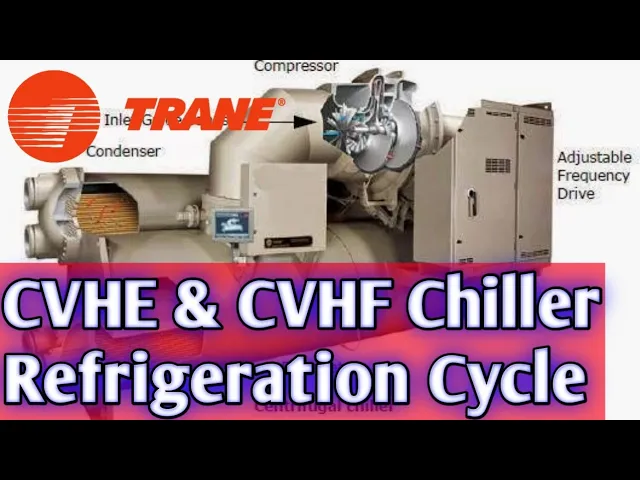
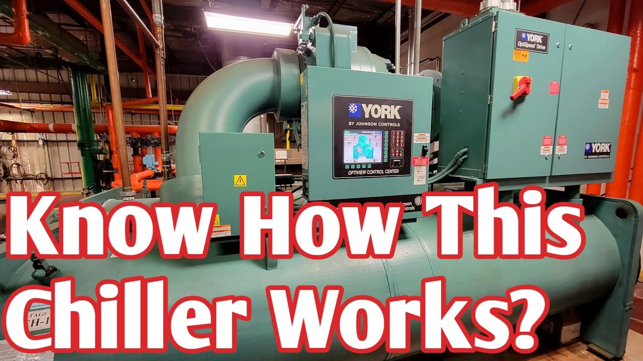
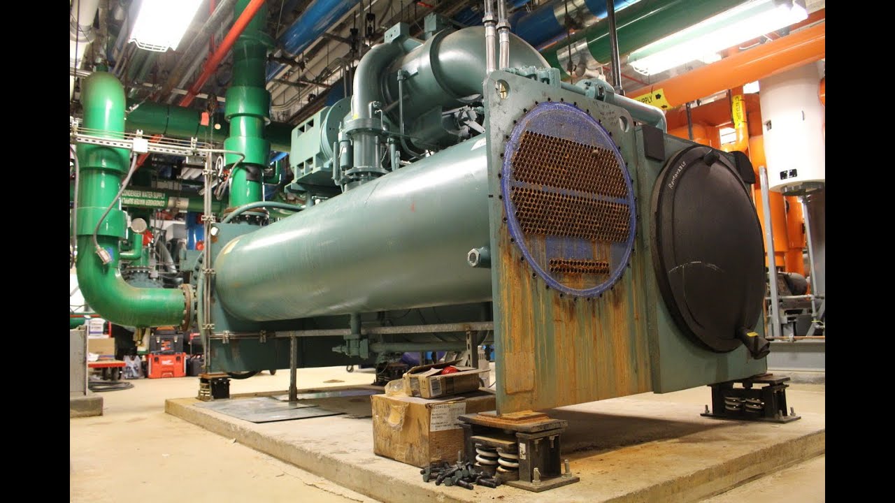
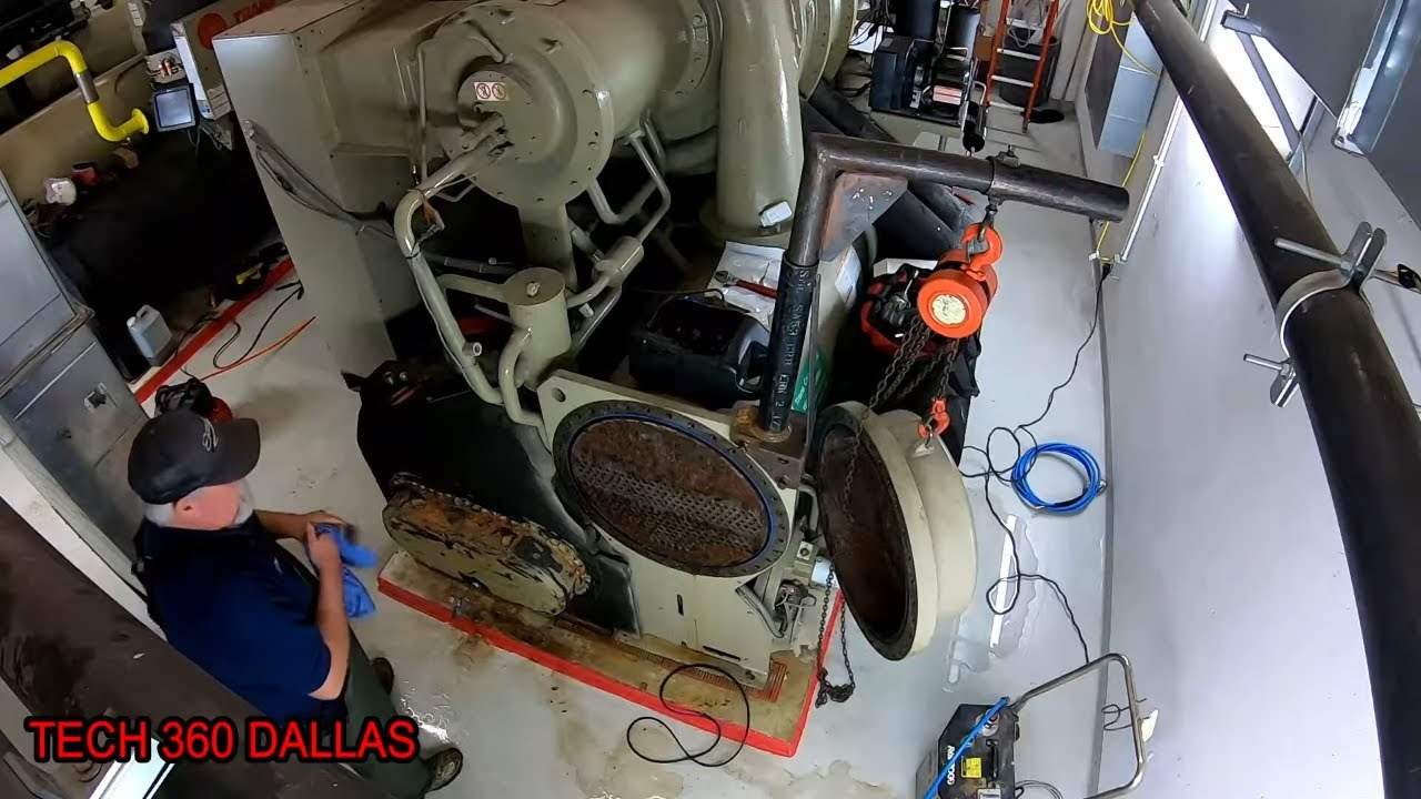
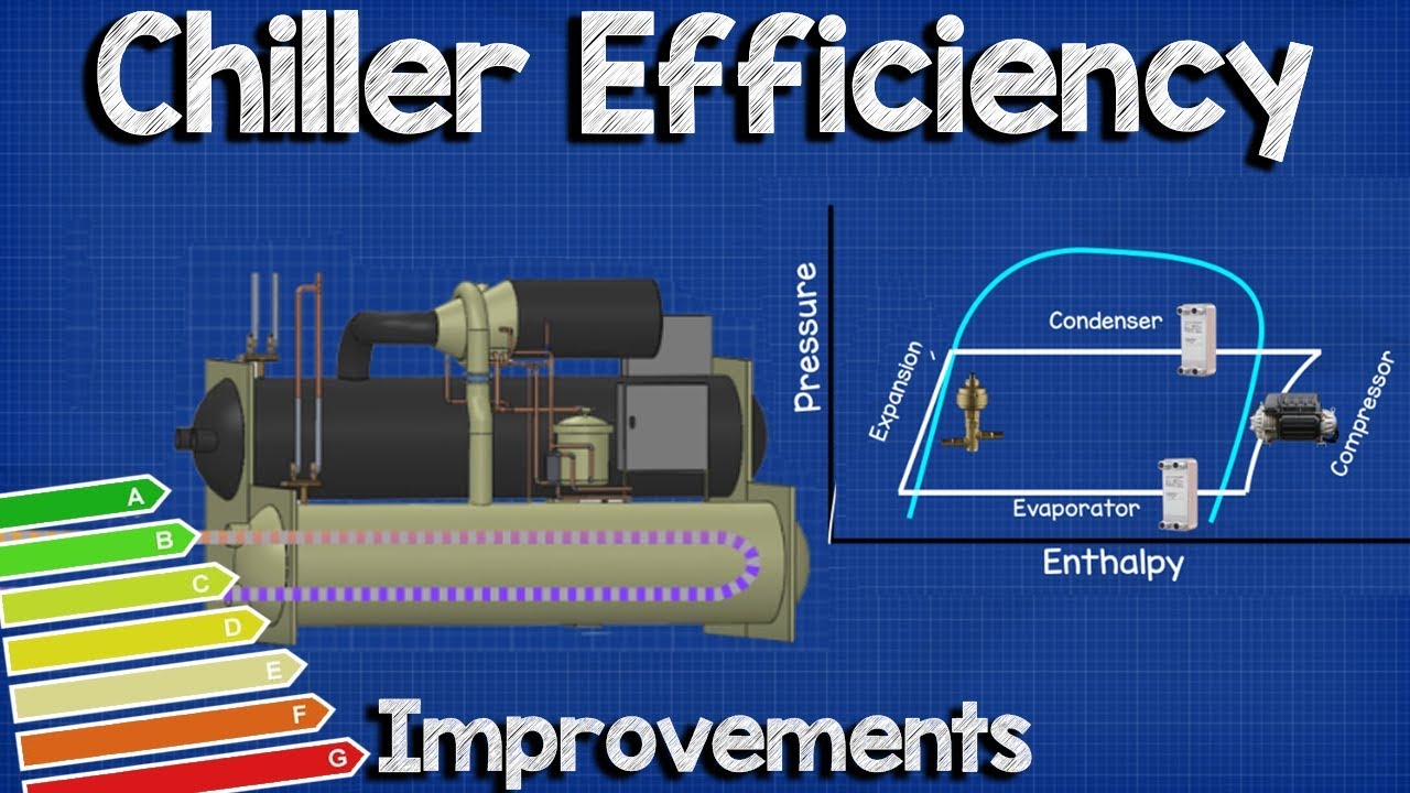
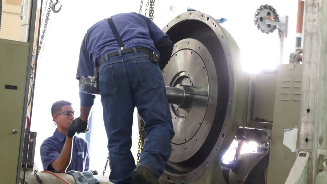
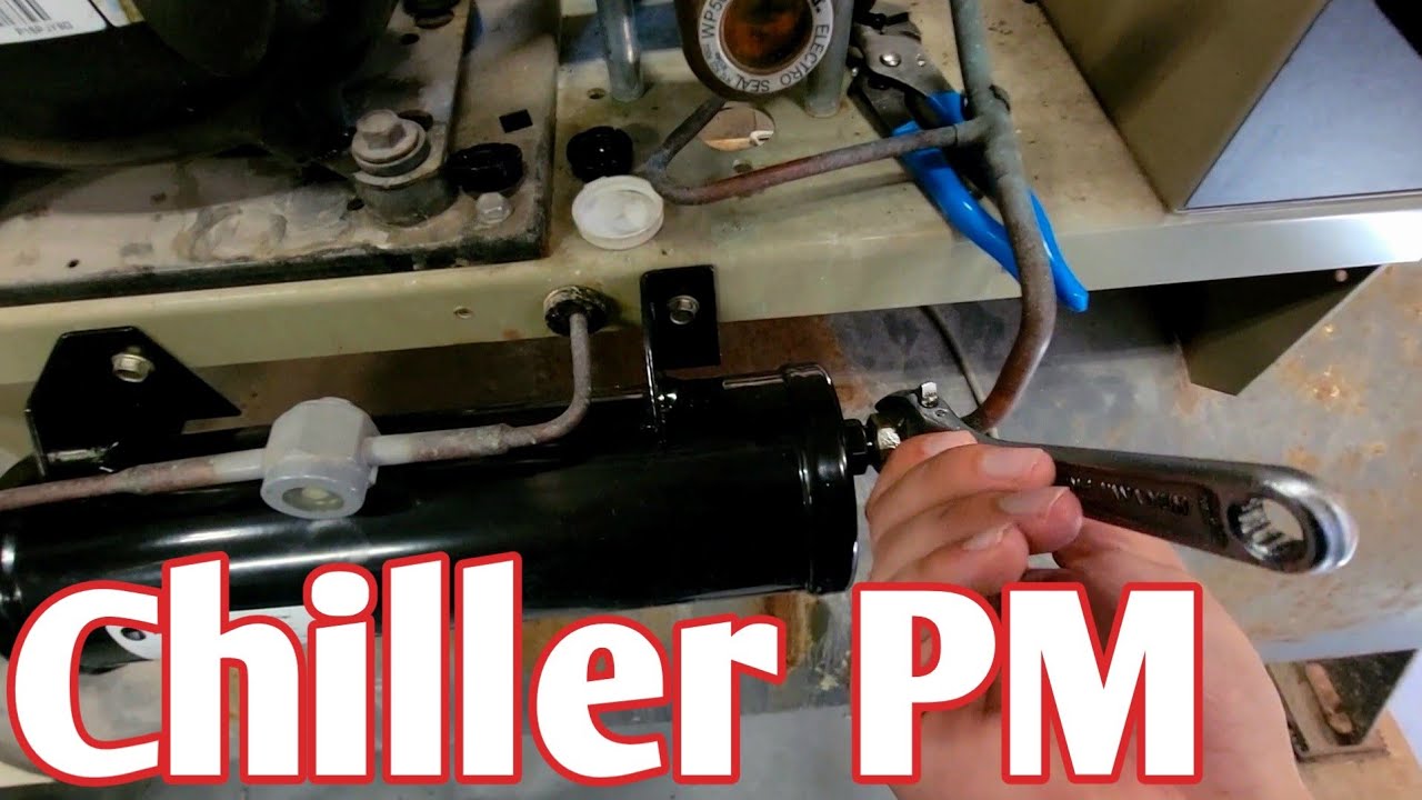
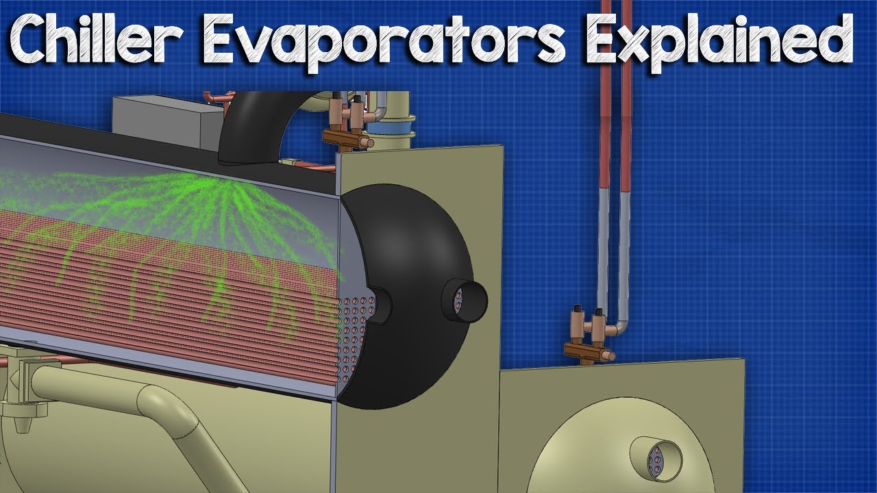
today we're going to be discussing the trane centrifugal uh cvh e and cvhf series chillers so let's just start with the basics end of the day you have an evaporator you have a condenser right everything's still the same this is your suction line coming into the compressor it comes in the compressor on this other side over here it's going to come out into the condenser these heat exchangers are known as barrel heat exchangers or specifically like this is a flooded evaporator design now there are a few other designs out there that do exist such as
falling film and hybrid type evaporators york is a lot more common to use those but this is this is just a basic flooded evaporator setup and what that means is all your refrigerant it just sits inside of the bottom of this barrel and it's in in the refrigerant is pushed into the bottom ports on the back side of this evaporator there is a port with a flash plate coming in that is feeding refrigerant into the bottom of the barrel and then we just maintain a certain liquid level in the bottom and all that's calculated in
it's it's not mechanically metered on these particular machines and you know the refrigerant gets just just gets pulled back into the compressor from there uh you'll see that they do have this little distribution plate the reason for this plate is so that you know you've got this big suction volute coming through you you really want to distribute all of the pool across that liquid refrigerant evenly the refrigerant is going to be below that plate level and so you're going to have all your liquid refrigerant below that anything above that pulling through is going to be
all vapor and what can happen is if that plate's not there to distribute it it will cause the refrigerant to kind of collect or pull more heavily right here in this one spot and you won't get an even distribution or or evaporation throughout the entire barrel which which then just heavily impacts efficiency it impacts everything you know that's not what we want something we're looking for so anyway uh this distribution uh plate allows that and really all it is is just a screen mesh i do have some tear down videos i've done where i've i've
kind of shown what that mesh looks like so you can go check those out see what those see what they physically look like in person if you've never seen one the refrigerant is on the outside of the tubes in this particular case and most all of your water cooled equipment it's going to have the refrigerant on the outside of the tubes when they're using a barrel now some of the air cooled that is the other way around and i explained some of that in the yciv refrigeration cycle video and the fact of many many in
trains the same way in this way on their rtaa and other series is uh most of their especially older equipment is going to have a dx uh barrel and so these are not that way though these are flooded i'm not going to dive into that here i've talked about that in a number of other videos regardless your water is going to be what's on the inside of the tube so this little shiny pieces here these are your physical copper tubes that go through the heat exchanger and that's where the water sits inside that's what we
take a brush machine and do routine maintenance on anyway we come through into the compressor this is your relief here now these machines that we're specifically discussing are still low pressure machines and which means that they're either running a 123 or a r11 on some of the older ones uh a majority of your new ones are going to be 123 and the newest ones that are coming out uh they are developing some other refrigerants i'm not exactly sure as to which ones they're going to commit to there's several that have been discussed over time but
not any of the manufacturers have outright committed to a one specific refrigerant at this time so this relief is actually a 15 psi burst plate and it is it's exactly what it sounds like uh if you get this suction elbow and many people do this during repairs i've done it myself for that matter uh you you get this suction elbow above 15 psi it's gonna blow and when that when it goes it's about a five five hundred dollar part most of the time uh it's it's uh it's it's done i mean there's nothing else to
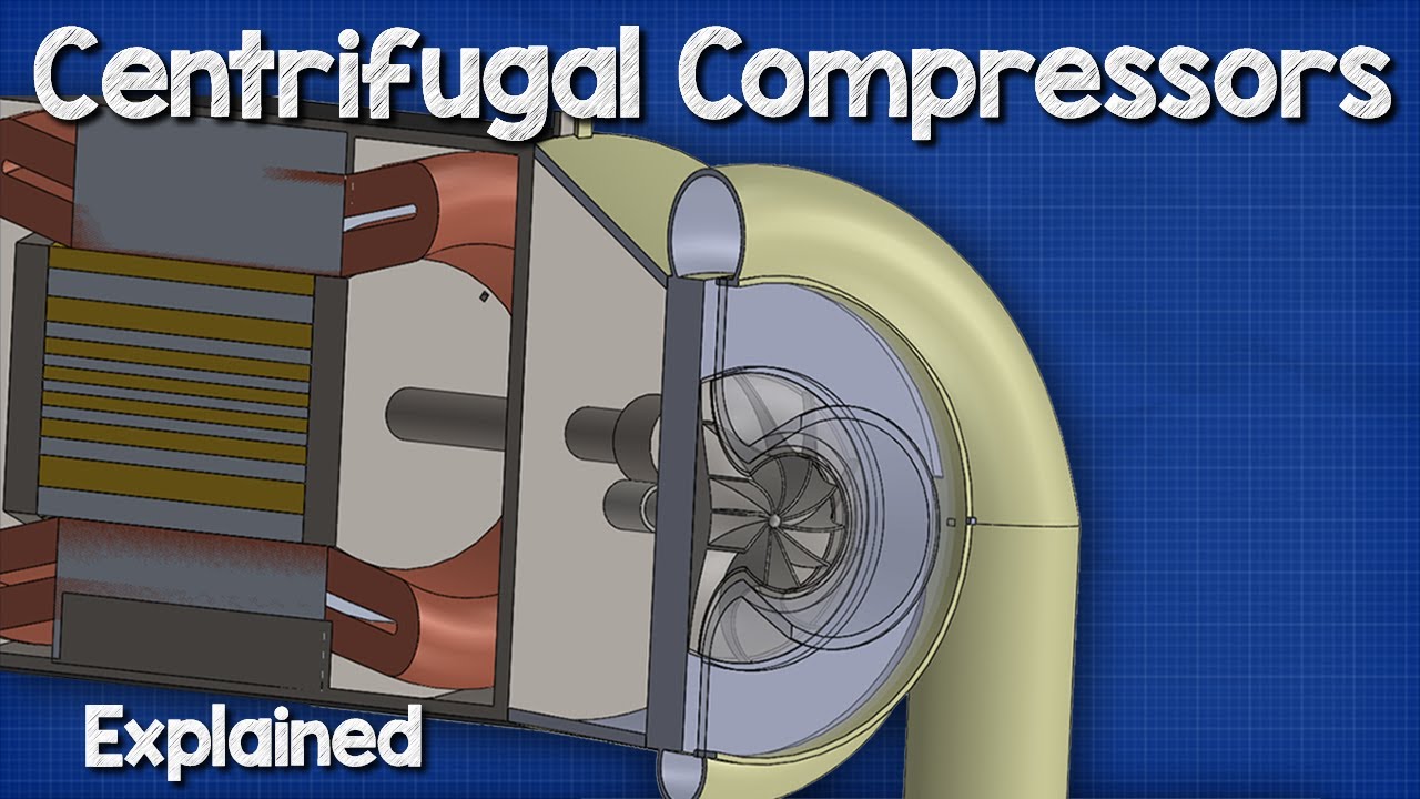
do for it when it cracks when it ruptures it's done anyway refrigerant pulls through comes through the suction elbow into the compressor now this very first thing you're going to see right here these are your inlet guide vanes your inlet guide vanes uh are that's how you control or flow through this machine so basically this is your load control this is your unloader solenoid valve this is your staging of multiple compressors you know for example say it's a two compressor machine well you're going to want to run one compressor for half capacity well instead of
killing a compressor we're controlling these guide vanes another example you know if you're familiar with screw compressors um you know this is your slide valve or if you're you know your this is what controls the load just end of the day whatever version of load control you're familiar with this is how this machine is doing it it's doing it through these guide vanes and they literally they'll they'll just close off they open and close and they're just as simple as that they're not a complicated piece of equipment they do fail they do have issues and
that's all for another video but this is what's going to do it so at the start up of this machine these guide vanes are going to be in full closed position if they're not you're going to have issues it's more specifically the main issue that usually happens is the compressor will over amp at startup so when it goes to turn on it will over current and it's going to give you problems there because of the over current and that could be because say there's you know a dozen veins in there and one of them the
armature just breaks on well when the armature breaks it ends up uh just causing it to um to just it'll get stuck in a single position you know maybe it won't close like it's supposed to all the way or something along those lines when that happens i mean yeah guess what you're gonna that's what you're gonna have train is a lot less tight on their tolerances compared to somebody like york york tells you that if you can fold a dollar bill four times and then make it fit between the veins when they're closed and york's
veins actually overlap each other they have to be machined in the yorks chillers aren't going to do well uh they're going to give you trouble specifically like their yk and yt series train is is a lot more loose with that they're not near as restrictive and their veins don't actually overlap they kind of just butt up to each other so much different design much different setup in that way but still nonetheless that's going to be a critical component to this entire machine and its calibration and this is controlled by a little armature right here now
i have done a uh train centrifugal overview as well i have two of them out there the very first one which kind of has some of my old branding on it there was some kind of weird thing happened with the footage at export and i didn't catch it and so the back half of the video doesn't actually work it just it's just dead space uh actually it was kind of weird but i did release the redo the video re-release it and made some actual upgrades to it along the way once i realized what had happened
and anyway i will link that video in this section of the video here but this is what controls the guide vanes and there is two sets of vein controls in this machine just something to be aware of i go through all this in person on site on the machine itself in that other video regardless evaporator through the suction into the guide vanes and then we start hitting the compressors and from here let's switch over to our next slide so we'll take a couple of minutes and spend it right here so this is just a very
basic very crude uh set up in a lot of ways but it gets the point across right so this is essentially what's happening here this is our evaporator we're pulling off through the suction veloute these are your little guide vanes right here this is your impeller for the compressor and then we're coming out the discharge back into the discharge line into the condenser uh we then take and use the condenser water to condense the liquid down we come through an orifice here and then back into the evaporator i'm not going to spend a whole lot
of time on this this really is these they function off the same basic design principles every machine runs from but again it just just some sort of visualization to kind of it might help with the rest of this process from here this is our suction line coming in okay so from that other example we're going to talk a little a little deeper into the actual cycle of the system at this point so this is your evaporator we're pulling through the suction volute through the guide vanes they're going to be located right here and into the
impellers now there's two impellers here and this is where trane and he has a very different approach than many manufacturers so somebody like york uses a high speed design and i believe carrier does as well where you know they have a bull gear set up we've got a low and high speed gears and they're running the ones one impeller and usually a smaller impeller at that to move the same volume of refrigerant uh from experience though those it's a great design it's a great theory but those do have a tendency to have a lot more
trouble with surging and things that's one thing's one prop i will give to train is they have a very solid design that is just it's it can take a beating pretty good honestly i see a lot of them very mistreated and they just they just keep working but uh theirs is a what's considered a low speed you know design so they have very large impellers okay especially compared to the other manufacturers and they're used multiple of them so they stage their impellers in such a way to where they can run this motor at a standard
speed i think it's either like 1800 or 3600 rpm like a general motor speed you would have on on any typical commercial motor there's nothing fancy but they can do that and still get the same amount of volume and flow and things and efficiency through these impellers and into the multiple staging of them and so a stage one impeller feeds stage 2 impeller which then is your discharge line coming back out of the compressor into the condenser and then back through again this is not a super complicated process at the end of the day we're
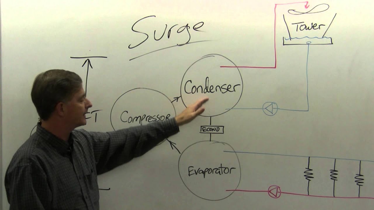
not i'll talk about surging and things a little bit deeper into the video we won't go into it right this second but it's it's not as complicated as it looks it's big it has a lot of extremely tight tolerances and so where people get in trouble is understanding you know the tolerances that are required in order to keep this machine fully functional that's where people get in trouble but the actual concept of the design is not the the complicated part it's not the hard part the design itself is honestly pretty simple we come down we
come into into the condenser so the condenser is is it just a standard everyday condenser right there's nothing really fancy going on here on a trained machine we're just processing water through pipes it pulls the heat out of the refrigerant that you know and then send it off to a cooling tower anyway coming out the bottom of the condenser here this is where train gets a little more interesting coming at the bottom of the condenser you know we have our liquid line and you're going to go through a first stage flash okay so this is
just a flash plate coming into what is known as the economizer so that big black tank on the side of the train chillers is your actual economizer and this is like i said this is just an orifice plate okay it's the same exact concept as any other orifice uh it's just this is a literal plate that has a basically a lot of perforations in it so that it can just restrict the flow and create that pressure drop which it enables the flash okay so that's what we're trying to do we're trying to create a pressure
drop which is what any meteor device does and it makes the refrigerant flash due to the pressure drop so uh what always happens you know txvs are the same way or any metering device you when you have that flash you say i use the 80 80 20 rule right so eighty percent of the refrigerant stays liquid and it actually sub cools even deeper all right so say it was five degrees sub cooled here well it may come out the other side of the flash plate uh you know 10 degrees sub cooled and the heat that
was that allowed that eighty percent liquid to go from five to ten degrees of sub cool gets trapped in that twenty percent of vapor that flashed off okay so that twenty percent of vapor then comes into this economizer and gets collected at the very top well that's there's a pipe there's a there's a um a pipe connection that goes in and bolts into the side of the compressor housing all this is mounted on the condenser side by the way so from the condenser view of the unit there's a pipe that goes up and bolts into
the compressor housing and and between the first and second stage impellers and it's getting pulled into the second stage impeller suction and so that impeller is pulling all of that flash gas back into the system to recycle it and so yes we do do we sacrifice a little bit of capacity here yes that is that is the final answer anytime you use an economizer you're always going to sacrifice a little bit of capacity but your efficiency dramatically increases when you do a setup like this it doesn't matter whether it's a you know a flash tank
you know type economizer like this which you know york also uses uh or if it's just a like a a brace plate heat exchanger with it with a metering valve on it you know all the brands use some form of carriers real common to use those those uh brace plate heat exchangers for their economizers so anyway it's all the same basic function yes you lose capacity you gain efficiency the vapor gets pulled back into the compressor then we come over and so now we've got this this 10 degree sub cooled liquid refrigerant coming through and
we we we're going into the outlet of the economizer as a pure liquid again okay so coming into the economizer we're at that 80 20 coming out we're back at a full liquid state then we go through the final flash point which is the second stage flash where we then enter the evaporator and so this flash is one it's a lot less of a flash so i don't have the hard numbers but i'll use an example say it's a a 90 90 10 or maybe a 95 to 5 ratio this time where only 5 or
10 percent is actually flash gas versus um you know it actually being the full 20 for example anyway you get the point it comes in it's got a very minimal flash at that point it fills the evaporator we chill the water back down it pulls back into the suction and off we go we're running for the races and this again all this is a cvh f design cvh e does have a little bit different design we'll also go deeper into the additional components of this system because all that's part of this cycle right now we're
heavily discussing just the refrigerated section itself the main nuts and bolts of just what makes the machine operate so here's a little bit deeper view of the cvhf economizer specifically or also a two-stage chiller economizer this is the initial flash coming into the economizer you'll see the liquid just kind of sits in the bottom of a big tank all this vapor is getting pulled back into the compressor and then it flows back out into the evaporator this is just another visual representation to kind of give you the picture and and just a view of what
it is we're talking about and what it looks like inside again i have a video where i'm in person and i go through all of this in person where you can see the physical components and i talk pretty in-depth about them there as well but i wanted to do this to give you a very good in inside visual one of the things that i did not mention here that i will just throw in very quickly is there is a second stage uh guide vein but it's it's a very different design than the first stage um
and so it it sits in between the two impellers and it also looks very different the armature going that controls it is a very different design so just be aware of that there are two different designs but there are two two different sets of guide vanes on these machines the cvhe series that has three stages it also has uh just two guide vans there's not a third set of guide vanes in those but the location kind of stays the same in the fact that the first stage and then the final stage impellers are the ones
that get those guide vanes so what you're looking at here is a three stage design okay it's the same very basically the same picture but there are just a couple of slight differences obviously first and foremost uh this the cvh e series is gonna have this third impeller here okay so you've got stage one two three all each of these stages feeding to the next and it's just pushing through again you're going to have guide vein here there's going to be a guide vein here and everything else about this basically functions the same it just
has one additional impeller and you'll be able to see it visually on the compressor you'll you can tell by counting the ribs basically you'll have two ribs on a cvhf and a cvhe when you look at the compressor you'll see three ribs each of those ribs is is actually the the point at which the impeller sits the other difference in this design is here at the economizer so we kind of take the economizer to a whole other level you'll notice that there is a divider plate and there's an extra little piece down here and there
are two pipes coming off the economizer this is another way to identify am i looking at a cvhe or a cvhf a cvhe is going to have a two pipe economizer coming off the top for the vapor gas so diving into that a little bit deeper we're coming from the condenser into the initial the first stage flash that flashes off is the same exact scenario as the cvhf so we're doing dealing with an 80 20 uh ratio right so the 20 gets pulled back into the final stage impeller okay stage three and the 80 percent
gets pushed through a second stage flash plate here inside the economizer this is all built into the economizer so we go through this second stage and it all flashes off this pulls in to the this pulls into the economizer on the second stage impeller on this other tank and again it's the same scenario flash gas sits up here liquid refrigerant it gets even more sub cooled so right so we gain sub cooling here on this liquid refrigerant we gain even more sub cooling here on this liquid refrigerant and then it comes back out 100 percent
liquid back in going to the the third stage of flash on the final uh plate going into the evaporator and so this is physically located at the evaporator itself and it's it's all right there where these sit are inside of flange bolt housings and so there's there's actual flan flanges that'll bolt up and where that flange bolts on either side of the pipe on the machine that is the actual uh point at which that that orifice is sitting so just so you're aware usually this one is right at the actual housing of the evaporator like
actually molded into the evaporator it might have a short stub out maybe or it may just be part of the evaporator housing that was that was kind of molded in this will usually have a stub out to where it'll it'll actually look very much like this it'll come out the bottom of the condenser is part of the liquid and then it'll flash and then this this will come up into the economizer and it usually they'll be insulated from this point on so and you'll like i said you'll see these are i think like a four
to six bolt flange depending on the size of the machine other than that it's it's it's all the same right would come through the evaporator guide vanes compressors all of us the same this is what's extra now let's cycle over and we'll take a look at the graphic of this economizer and here you go so this is the basic graphic we're coming in first stage come through this gets pulled out into the third stage impeller we go through this kind of bottom chamber here through another orifice uh into the second they're the second stage of
the economizer which gets pulled into the second stage impeller and then back out to the evaporator it's it's pretty straightforward right it's it seems very complicated when we can't really visualize it and it's hard to picture what all is happening in there and especially even the manuals can really kind of struggle really explaining this in a way that that makes sense especially to somebody that's just brand new to this entirely and just trying to figure it out hopefully this explanation will really kind of help break this down in such a way to where it makes
a lot more sense i wanted to show this picture for a couple of reasons this gives a really nice graphical representation of the compressor itself right so this is the piece of the machine that i think tends to give everybody the most trouble and understanding end of the day you've got a ball bearing back here you've got your bearing assembly up here this front assembly does have a journal bearing so just be aware of that and i'll explain that deeper here shortly this is a very accurate representation of the guide vane assembly for the first
stage and this is again this is the armatures that you see if you go look at my other video it'll you'll see these exact same armatures that control them and this these little ridges here are part of that vein assembly uh and its ability to control these motors are semi-hermetically sealed just like the depiction says this is all part of the refrigerant stream uh it's all built in you know so some of the other say york for example uh they're some of their centrifugal chillers the motor is external it's not part of the refrigerant stream
train does train i think also carrier carrier many of their chillers motors are also built into their stream so anyway it doesn't matter just something to be aware of this is your terminal lugs so we're talking refrigeration cycle here so the reason i'm going to bring this up is just one it's it's a really nice kind of graphic depiction but two i've i wanted to also use this as an opportunity to talk about some of the oil management as well and how that factors in and part of that is this little flash tank right here
so this is a vent tank slash oil separator it's got several jobs it functions in it's kind of it's more critical into what we're discussing now and the fact that uh this is what prevents a lot of oil from getting back into the condenser and specifically the evaporator it also uh allows the oil tank or the the uh oil reservoir to vent its vapor that may collect into the top of that of of the tank back out into the evaporator another thing you can see here that's pretty nicely displayed is these right here this little
line it may be kind of hard to follow i'll try to explain this better later here we can draw this here this pipe right here right there that pipe is part of the motor cooling circuit okay so this is the drain pipe that the refrigerant that gets pumped into the motor housing drains back through to to reintroduce the refrigerant back into the system and so that's something that we should talk about now is this is part of our refrigeration circuit on these machines is we have to keep this motor cool we keep it cool by
pumping refrigerant into the motor housing oh back over here you can't see it from this angle but on this side of the system there is a third pipe that lands in between these two drain pipes that is pumping refrigerant into the motor housing and it goes through a little flash orifice plate that allows that pushes liquid refrigerant in there and gives some cooling to the motor and then the additional refrigerant as it you know cools the motor down just flows naturally through gravity back down into the condenser side of the system continuation of that all
of that conversation leads us to this point so this may look very uh intimidating and that's okay so let's break it down as best we can so before we get into any of the rest of this let's just first get some our bearings as to what it is we're looking at so this bottom piece the machine here this is your evaporator right you can tell this is the compressor this is this particular one we're looking at we see there's one pipe coming off the economizer here's the motor we count one two ridges okay so all
of these are identifying this is a two stage machine being a cvhf series this is our suction volume coming in um the discharge is right over here so this would be your discharge line and all this kind of overlays that's why i want to just give some parameters first and this top cylinder kind of up here almost in the background this would be your condenser back here evaporator condenser and you know compressor suction economizer vent obviously this would be the economizer these are the pipes so right here is the pipe coming off the bottom of
the economizer going into the economizer your flash plate would be somewhere right about here and then coming out of the economizer back into the evaporator which this here would make that flash plate there this is your oil sump right here uh so we'll we'll dive a little bit deeper into that but we'll finish specifically all the refrigeration side of the circuit and then we'll talk a little bit about the oil management and just kind of how that plays a factor so like i was discussing earlier right here is that drain coming back into the condenser
for the refrigerant after it has finished cooling the motor that is being fed from down here so coming off of the liquid line right here into this little assembly here at the sump this is actually a refrigerant pump that is tied to the mechanical oil pump inside of the oil sump so the oil pump runs the refrigerant pump to where it is pulling liquid refrigerant in and then it pushes it from there up into the compressor housing through this little orifice plate so this is what assists the motor in maintaining a proper temperature and cool
operation you know while it's running and again all of the additional refrigerant that collects in the bottom and it all siphons back down into the condenser from here but this is your motor cooling circuit this is what your refrigerant pump is doing and that's what those extra lines that are coming into the oil sump there if you're ever looking at the face of one that's what they are this is it's all part of the motor cooling side of the system the other part of this refrigeration cycle and this is kind of the final piece for
what we're dealing with the rest of this will pertain to the oil management side is we feed up this is your vent right here that goes back to the evaporator so any vapors anything that collects in the top of this tank or the sump is allowed to process through this pipe here into this little oil separator we were discussing earlier and then once it comes in the side it's allowed to then just vent back to the evaporator through a pipe so it's just pipe back into the evaporator and the low low pressure side of the
evaporator allows it to pull back through so just something to be aware of is that that's that's how the additional vapors that collect here get vented next we will discuss the oil management side of it i will pro i might end up doing a separate video on just this oil management side just going into greater detail on it specifically but in the meantime we'll go ahead and cover it here because it does play a factor as part of the system so this is your oil sump there is a pump and this little device right here
is your oil regulator so what it is doing is you come out the regulator through a cooler inside the economizer so this cooler is inside in the economizers is exactly that right it helps uh process make sure the oil you know is it maintains a proper temperature going into the compressor it's why it's also important that we maintain a proper oil temperature inside the sump so that you know in any additional cooling that needs to happen we've got we've got the proper temperatures in order to get the right oil temperature to the compressor so then
we come out here and we kind of tee off into two lines so this this uh back line feeds your rear bearing on the motor right and the front line feeds the front bearing and specifically more importantly the journal bearing we can go ahead and talk about that a little bit now so one of the things that is real critical is these have a they're not super tight parameter in the window on the oil temperature side but it's not you have to be really careful with it so these machines if i remember correctly uh without
re checking the manual real quick don't won't allow you to turn on until that oil is either 110 or 120 anything below that it will not allow you to function i believe it's a hundred and it's 120 that's what it is so below 120 degrees this machine is going to give you a low oil temperature uh indication and it's going to be trying to run the oil heater until it gets above that now that oil heater only runs when the machine is off and it's gonna it's trying to maintain that oil between 140 and 160
when the machine is off now once we get the machine online we want that sump to be able to maintain around 120 to 140 degrees is pretty typical you just don't want to go below that 120 mark the reason this is so critical and so important is because that oil at that temperature has a very specific viscosity okay and so it's it's what it's designed to it's lubricating parameters everything that we need it to do and be in its life revolves around that set temperature range anything outside of that it starts to become too thin
or too thick in order to do the job or asking of it if everything was just standard ball bearing it wouldn't be as critical but and many centrifugals use these what are known as journal bearings okay so a journal bearing literally kind of uses the oil as the bearing seal okay so the oil gets pumped into the the journal and the bottom of the journal will have these kind of trough looking uh indentions kind of machined into it and it'll have usually two oil ports there sometimes some of them may have a third one on
top but most of the time you'll have two on the bottom and so that oil gets pumped into that lower port or portion and it that's that's what is helping kind of lift the shaft and also um it's it's designed in such a way to when that oil gets pushed in there it literally creates a oil ring uh that separates the actual steel shaft from the aluminum bearing and so most of those journal bearings will tend to be an aluminum material which is not going to take a still shaft coming into contact with it with
any grace it's going to be very upset with you for doing so what is critical there is that we we've we've got to maintain the oil within those set parameters so that we make sure that that journal bearing functions properly so that it doesn't you know cause any damage the worst thing we could have happened is it that journal bearing not lubricate like it needs to and then that steel shaft comes into contact with that aluminum housing and just tears it to shreds and you'll you'll always know that whenever you go to do an overhaul
um you know you'll you'll pull that journal bearing out and it'll it'll be reamed out inside i mean it'll be usually it's just pretty obvious it'll have a bunch of scarring and all kinds of things because that that shaft was able to constantly be making contact so just side note but something to be aware of is that that is very critical and it does exist regardless moving on from there this port here this is the oil return for the front bearing assembly this is the oil return for the rear bearing assembly coming into this little
oil separator again the purpose of this is to take any refrigerant that gets trapped in the oil allow it a place to release so that it doesn't make its way into the sump some of it will that's why we have a vent on the tank itself but we're trying to prevent as much as possible from there the oil just gravity feeds down back into the sump and then back through the pump and out it goes you know you whole nine yards that is the the basic makeup of your oil management side of the system let's
talk now about oil return and oil management so there's three points of oil return that this machine goes through and you know they do reference to these as inductors okay again i'm not an expert on the adductor theory or design i just know that it exists and i try my best to work with it regardless uh the first stage inductor is right here coming right off the bottom of the sump its job is to just try to pull any oil or any any any oil that that will collect in this portion of the system oil
is heavy and so it's going to fall towards the bottom so any oil that is allowed to make it to this point this seductor's job or this return lines job is to try to draw that oil back into the sump this coming off the bottom of the evaporator here is your second dairy or your second stage inductor and again its job is to take any oil that collects in the bottom of the evaporator and draw it back in to the condenser or the the oil sump itself so this is the first stage this is the
second stage all these are doing the same basic job there is a little filter type device that this goes through uh it's just all part of that withdrawal sequence again i'm not going to even pretend to try to explain the science behind it i'm just going to tell you that it exists and then this is the third stage here coming off of the condenser okay so we've got three different pipes all three pipes job is to do its best to get all any oil that doesn't get trapped here and how this happens is basically uh
the discharge line you know there's some of the oil is going to get grabbed by the refrigerant stream in the compressor and it's going to get sent out the discharge okay so when that happens the most common points for that oil to be collected in is going to be this evaporator assembly and then coming into this suction line and then you know again they're trying to pull the vapor off the off of the um off the refrigerant and to process that oil back out of it and get it back into the oil sump this is
a very common issue that a lot of people deal with i've come up on several machines in this second stage line here it'll have a ball valve on it many times or a service valve of some some sort and it will be closed right so you have to be very careful of that and be mindful that and you don't want to just start pumping oil into these machines depending on the load conditions it's very common for the oil to have migration issues on these and when that happens you know that that oil had to have
gone somewhere if you don't see it sitting on the ground in front of you it's somewhere in the system right and so we we need to try to do our best whether it's get a high enough load on the machine make sure that the return lines are all open properly you know something to try to attract that oil back into that tank and get it i was just a gentleman i've been working with over the last several weeks if you don't know you're welcome to reach out to me through my facebook page at hvac time
on facebook and reach out to me through the messenger there and i will do my best to try to give you any tech support that i can on whatever equipment you're working on you know if it's something i can't help you with i'll just tell you hey i'm sorry but i'm not gonna be able to do much for you on this regardless we and him have been working through a situation he was going through and he ended up finding uh that he had a valve that was that was having issues and if i remember correctly
it was the vent valve uh coming off of the separator uh it was not opening properly if i remember correctly i'd have to go back and read back through our discussion i'm trying to pull off top of my head now anyway point is he was having an issue with the machine came came in they got it installed they started it up and it just all the oil disappeared and uh you know that that was because the oil return side of the system wasn't functioning properly he had a valve that wasn't working right and it was
causing the uh oil to not get returned back to the sump you know just it's it's very very critical that you keep up with this side of the system one of the things that i have not discussed this is number 14 here this is the purge assembly um this purge assembly's job is just to because again these are low pressure machines r11 and 123 are low pressure they operate inside of a vacuum they are not positive pressure high pressure machines like 134 r22 14a blah blah because they operate in a vacuum they do allow a
lot of atmosphere that has a tendency to you know seep its way into the system and so it's it's routine and common that this purge assembly just has to occasionally kick some of that out of the system this purge assembly is a is a video in and of itself and just kind of giving its breakdown its function is purpose this video is already getting long enough so i'm not going to go in depth into that here i will plan to do another video on that at a later date and time and kind of talk about
the regen tank and some of the the different changes that have been made to those over time right now train is the only one that i'm aware of that i can think of that is still using low pressure machines i do know that york is going to be if they haven't already announced it they will be releasing a low pressure lineup again in the coming years a couple of years i think was last conversation i had with one of their factory guys so we'll see we'll see what that lineup does and obviously if it's a
low pressure machine it's going to have a purge assembly to manage atmosphere and things in the system but i do have a lot of videos already out there on the purge assembly regardless i won't talk anymore about it i have talked enough throughout this video now so we'll conclude it here i really appreciate y'all sticking around watching this and i hope you get a lot of benefit from it um you know i if you have any other types of videos like this any specific in-depth deeper trainings that you're really looking for that would significantly help
you in your process your system you know or just your training let me know because you know there's a whole heart of what i'm trying to do here is i want to be able to provide you with the information that you need so that you can you know provide a better life for yourself for your family i really appreciate sticking around to the end of the video i always make sure that we're putting in the time to our families as well you know we this career path requires an immense amount of energy and everything from
us but we cannot lose the site that we we have to take care of our families at the same time so uh just make that time mtt is one of my slogans i've come up with over time and just we have to make the time time's never going to be there we have to make it anyway y'all stay safe this summer and i will catch y'all in the next one