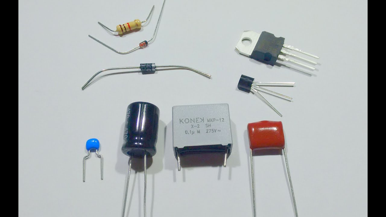
hi it's mr. roots from Lansbury science here and I'm going to show you how to do the physics practical on finding the IV characteristics that is how does current change with PD for different components what we're going to be testing today is a resistor and mine is a 100 ohm resistor I have my filament lamp here as well and also a diode which is this little thing here what else you're gonna need well you're gonna need a variable resistor now you will need a variable resistor that has a similar resistance to the resistor that you're testing as well so this is a 1 kilo ohm max variable resistor that's pretty good to use with my 100 ohm resistor if it's very different if it's too small that's usually what the case is then you won't get good results we also have a battery or a power supply you can use that too that can supply up to about 5 volts we have an ammeter and also I have my milliamp shunt here as well which means that I can turn it into a more sensitive ammeter which we're going to need for the diode I have my voltmeter as well and lots of leads this is a classic practical that is really fundamental for you being able to understand how these various components work and you need to know it inside out so let's have a look at how we do it first of all we need to build our circuit we're going to start with our battery or our power supply and we're going to just build one series circuit so we're going to take a lead and bring it to our variable resistor and then we're going to attach this to our component I'm going to test the resistor first now just make sure that's one of your leads actually comes from the middle of the variable resistor if you do it on both ends then you won't actually get a changing resistance here so you won't get a change in current and then we need to hook up our ammeter now a meters always go in series with the component that we're looking at so we're just going to take two leads one from the resistor and then finally back to the battery now I can see that my ammeter is giving a reading of minus 0. 06 amps and usually when we do practicals with circuits we tell you not to worry if there's a - it's just the same number it's just the leads are in the wrong way round but this time we do want to make sure that we have a positive current at least a positive current when we have a positive voltage so I'm just going to swap Miley's round in my ammeter to get a reading of plus 0.
06 amps the last thing that always gets added to a circuit is the voltmeter and the leads from a voltmeter always piggyback across the component that we're looking at so my two leads from my voltmeter piggybacking into the leads going into the resistor and it's showing me a voltage of five point six six and it's positive as well which is what we want so just make sure that to begin with both your current and your voltage are positive now because we're dealing with fairly low currents 0. 06 apps is the maximum that I'm getting here that's okay because we only need say five readings for the current and the voltage what I'm going to do is start at zero amps I'm going to bring my current up to 0. 01 amps using the variable resistor and we're going to go up in 0.
01 amps what's the voltmeter reading well it's reading exactly 1 volt so one point zero zero let's get a one decimal place with our voltage or our potential difference next I'm going to increase the current using the variable resistor to 0. 02 amps again making sure that it doesn't fluctuate that it's staying at 0. 02 I now have a PD of 2.
1 volts to one decimal place you're going to carry on increasing the current until you get five readings here are mine all the way up to 0. 05 amps but we have one more thing to do as well we don't just want to know what happens with positive currents and potential differences we want to know what happens with negative values as well what do you have to do to change the direction of the current flowing through the circuit just change the LEAs round in the battery or the power supply and as you can see I now have negative current and a negative PD of voltage as well it just means that current is flowing in the opposite direction through the circuit but we are going to repeat the experiment now starting at minus 0. 01 amps and then going down to minus 0.
05 amps not a big surprise the PD at minus 0. 01 amps is minus one point zero volts going down to minus 0. 05 amps this is what my voltages were for those what you then need to do is plot a graph and this is one of those times where the y-axis and the x-axis are going to be in the middle of the graph because you need to be able to plot minus values for both the current and the potential difference now which way do you put them around on the graph this is a little bit of a point of contention some people say that you must have current on the y-axis and voltage or PD on the x-axis other people say that it's the other way around chances are in your exam you will see current on the y-axis and voltage on the x-axis that's why it's called an i.
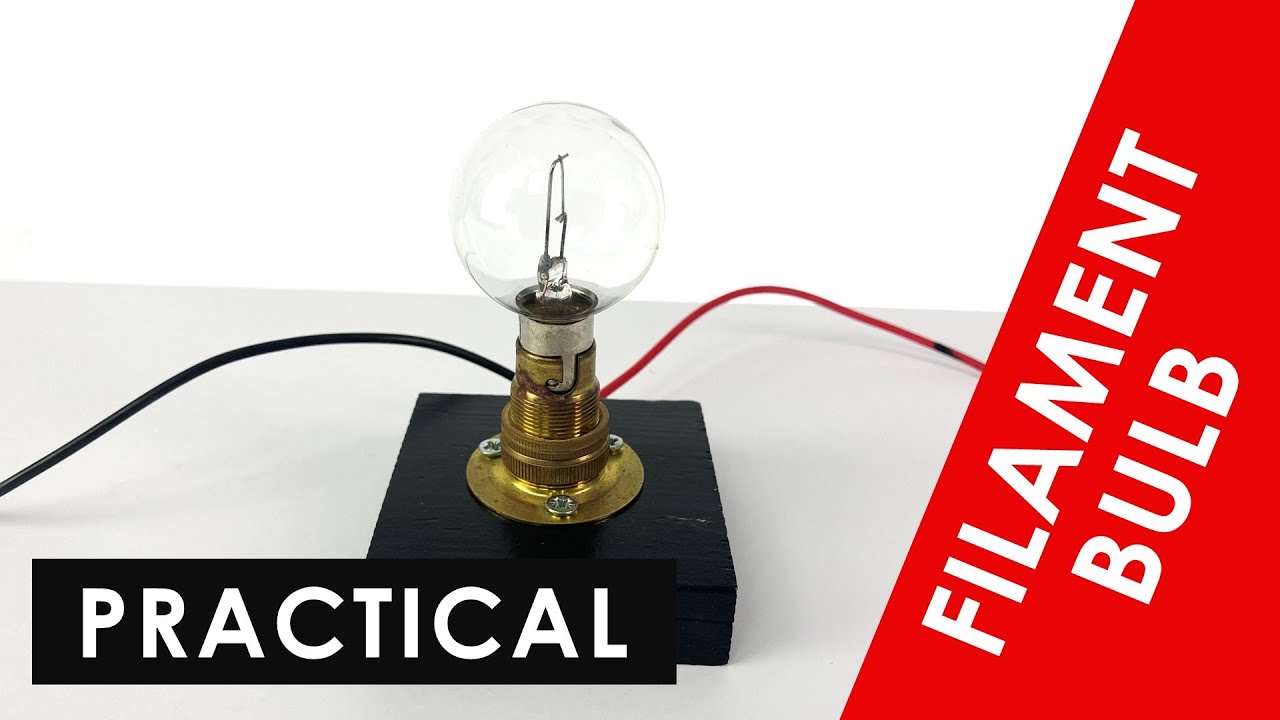
v graph now what can you do with this well as you can see my points make a nice straight line and you might note that Ohm's law states that voltage or PD potential difference is equal to current times resistance so if we have a graph of current against voltage then we should have a straight line if we are dealing with a fixed resistor because we have this straight line we can say that we have a constant gradient that means that the resistance is constant therefore we can say that this resistor here is an ohmic conductor that just means that it has a constant resistance regardless of what current and what PD you have across it next let's check the filament lamp all I have to do is unplug the leaves from my resistor and pop in my lamp instead it doesn't matter whether you start with positive or negative values you just need to make sure you do both so starting with 0. 01 amps I can see that I now have a PD of 0. 3 volts across it I'm just going to get the rest of my results for 0.
02 all the way to 0. 05 amps my final results of 0. 05 amps that needs a PD of 3.
5 volts in order to push that current through the lamp so having my negative values as well here's my plotted graph of current against PD as you can see it looks slightly different from the graph that we had for the resistor what's different about it well it's slightly curved and it curves towards the end of the graph both at the positive and the negative ends so what does this show us well if first of all shows us that resistance isn't constant for this lamp and so we can't say it's an ohmic conductor we have to say that it's a non ohmic conductor the graph flattens slightly towards the end that means that as we increase the PD across the lamp where the positive or negative we're less able to push current through the resistance of the lamp is increasing as the current increases now why is this when current flows through a component it gets hot this is because the electrons that are flowing through the components collide with the particles that make it up however a resistor it's made out of a special material that includes silicon which means that even though it gets hotter the resistance doesn't change however with a filament lamp as those electrons flow through the metal they collide with the ions of the metal what happens though when the metal gets hotter the ions vibrate more and that means the electrons collide more with the ions as they pass through so they find it harder to go through so that means the resistance increases and finally the diode now this is a little bit trickier so here I have the diode and it's in a little holder and there's my two leads piggybacking on it to go into my voltmeter and it's all in series with everything else now the difficulty with the diode is getting the PD down to a very low voltage now I've changed the output from my battery to three volts you really don't need a high voltage for the diode experiment now the minimum voltage that I can get down to across and my diet is 0.