Hello everyone. How are you all doing? This is Professor Andreia. Welcome to the electrical installations course. Today, in this first class, we're going to do an introduction and talk about basic concepts in installations. To give you an idea of what we'll be studying in this class, I've listed the topics that will be covered. So, firstly, we'll talk about basic concepts of generation, transmission, and distribution of electrical energy in Brazil so you can understand where we are in the electrical system when studying low-voltage electrical installations. We'll introduce the NBR5410 standard. We'll understand its importance. Fundamental concepts
about low-voltage electrical installations. We'll talk about the stages of an electrical installation project. And finally, we'll also talk about graphic symbols in installations. To begin, I think it's interesting to start by thinking about the path that electrical energy follows from the generation process to the end consumer. You certainly have an idea about this path, but let's point out the stages here and then we'll talk a little more about each of these stages. So, starting here , in section A we have the generation stage, with a figure of a hydroelectric power plant representing this process. Right
after that, we see a transformer indicating the presence of a step-up substation. From this point, we enter the transmission level, so the energy travels, reaches a point here, there may be another substation that will alter the voltage level of the transmission until it gets closer to the end consumer. And then we have another substation identified here as a distribution substation. At this point, we lower the voltage to a level generally of medium voltage. So at the distribution level here we have medium voltage (MV). Up to this point we have different types of consumers. There are
consumers who receive voltage directly at the medium voltage level. There are consumers who do not, the most common example we can think of is the residential consumer. So this medium voltage level reaches the transformer that is on the pole. This transformer is then responsible for lowering the voltage level once again. So, it takes the medium voltage level, then goes down to the low voltage level, and the end consumer, the small consumers here at the residential level, for example, receives the energy at low voltage. Depending on the type of consumer, as I told you, this may
not happen; they may receive medium voltage, they may have a dedicated transformer, or a single transformer may be able to supply several consumers, in the example of residential use. So, it depends a lot on the characteristics of the consumer, but in general, that's the path that electricity follows. So, when we talk about generation, here in Brazil, certainly one of the first images that comes to mind is a hydroelectric power plant. So, we have an image of the Itaipu hydroelectric power plant, one of the largest power plants in the world. In addition, we also have other
sources that we use here in Brazil. So, I included a representative image of a thermoelectric power plant. The thermoelectric power plant has a relatively small share in our energy matrix, and it is non-renewable. We also have a small share of nuclear energy. We have two nuclear power plants, Angra 1 and Angra 2, operating in Brazil, generating energy from nuclear sources. And we have a third plant, Angra 3, which has begun construction, but the works are stalled and there is no completion date in sight. Well, we've observed a growing trend in recent years of growth in
other renewable sources, such as wind and solar power. So we've seen a very large increase in research and investment in these new renewable sources, wind and solar. And the trend is that they will increasingly increase their representation in terms of our energy matrix. In addition to those I've mentioned, of course there are other sources, right? Biomass. Within thermoelectric plants we have coal, gas , and oil. So this is our general scenario in terms of generation. No. To give you an idea of what we're talking about in quantitative terms, I've included here for you the power
generation supply matrix in Brazil. This information is taken from the Brazilian energy review, from the latest edition published in May 2020. This edition, by the way, takes into account data from the previous year. So the base year is 2019. Let's see how our electricity supply matrix is structured. As we expected, we have the supremacy of hydroelectric power, accounting for 61.3%of this source. However, it's not just 61.3%, it's 61.3 %plus this 3.3%of imports. Where does this import come from? This refers to the Taipu hydroelectric plant, as you probably know. Half of it is from Brazil, half
from Paraguay. But Brazil buys some of the energy generated by the Paraguayan plants. That's why we have this import here, this energy that we buy from Paraguay, but it comes from the Taipu hydroelectric plant, right? So, in reality, from hydroelectric power, we have 61.3%+ 3.3%. Well, for the rest, we have other renewable and non-renewable sources. See here that it says on this side that the share of renewable sources is 84%in Brazil's energy matrix. And this rate is much higher than the world average, which is currently around 37%. What are the components of renewable sources? Well,
we have hydroelectric power, imports, which are also hydroelectric. We know that 8.6%of biomass is also renewable, and 11.1%of wind and solar power also fall into the renewable category. The rest here—nuclear, oil, coal, industrial gas—these are the non-renewable parts of our energy matrix. So, thanks to a great deal of our natural potential, we have a share of renewable sources much higher than the world average. Now, we have data here that I got from the ONS website, which is the national system operator. In a moment I'll explain to you in more detail what the ONS is and
what its function is in our Brazilian system. Well, this figure is interesting because it shows us the installed capacity in the national interconnected system in 2020, comparing it to the forecast for 2024. So, look at what we have here in terms of hydroelectricity. In percentage terms, we have a reduction in the representativeness of hydroelectric power, but this doesn't mean that the amount of power generated from hydroelectric sources will decrease. See, it will even increase, from 108,000 MW to 109,000 MW in 2024. However, the representativeness will decrease because other sources will increase, right? So, in percentage
terms, it will decrease a little, but it will still be more than half. Look, the forecast for 2024 is 61.9%. We have a gas-fired power plant with LNG in 2020, 14 MW, and a new one in 2024. So, there's a forecast of increased wind power; we also see a significant increase. We have 15 MW in 2020 and we'll go to almost 20 MW in 2024. So, in percentage terms, the share will grow from 9.3%to about 11.3%. Thermal power plants, notice that there's practically no change in these 4 years, no forecast, right? It will remain at
2.7%. The thermal power plant, the one I mentioned in orange, is oil-fired, oil plus diesel. We also have coal-fired thermal power plants. That one won't change at all. You see? 3017 MW in 2020. It will remain 3017 MW in 2024. Biomass, we observed a modest increase, but it's an increase from 13,600 MW to 14,500 MW. Solar power, folks, will increase, if you observe, its share of the overall percentage will still be small in 2024, right? It's projected at 2.4%. But it's a good increase from 2020 to 2024. The forecast will go from 2900 MW to
2900 MW. Well, regarding nuclear power, there will be no change. As I told you before, there is another nuclear power plant under construction, Angra 3, but there is no completion date for it. That's why the amount generated remains the same for this period. So, in total, what do we observe? Okay, we're going to see an increase in installed capacity in our Brazilian system from 164,620 m³ in 2020 to 176,535 m³ in 2024. And in general, we observe that the trend is always towards increasing the representation of renewable sources . Previously I mentioned the national interconnected
system. But what is this system? We call it the acronym for national interconnected system. This system, according to the ONS, which is the national system operator, can be defined as follows. Read here: The electricity production and transmission system in Brazil is a large-scale hydro-thermal-wind system, predominantly hydroelectric plants and with multiple owners. The national interconnected system consists of four subsystems: the South, Southeast, Midwest, Northeast, and most of the North region. So, currently, only a small part of the North region is not connected to the rest of the national interconnected system. So, think of our electrical system
here in Brazil as one large, interconnected electrical circuit. Why do we have this configuration of the electrical system? What are the advantages of having an interconnected electrical system? We can think of several advantages. Our system, in this way, becomes more robust, more reliable, its operation is more reliable, and we have greater freedom when we think about how to manage this system. Because our country has a very large territorial extension, there is significant seasonality. So, sometimes, we can take advantage of the hydroelectric potential, the natural potential of some parts, and manage this energy in the best
possible way so that all regions are adequately supplied. Therefore, with this interconnected system, we can organize how energy will be generated, transmitted, and distributed throughout the country in the best possible way. It is in this context that the ONS, as I mentioned, the national system operator, comes in. What are the responsibilities of the ONS? Its responsibilities are shown in this figure. This image I took from the ONS website itself, okay? Here: s.org.br. So, their responsibilities include network expansions and reinforcements, planning of electrical power operations , integration of new installations, programming of electrical power operations, transmission
management, system operation, and operation evaluation. So, note that the ONS is responsible for planning, expanding, integrating, and operating the system in terms of generation and transmission . Therefore, the ONS takes care of generation and transmission. We'll talk about the distribution level in a moment, but the ONS doesn't handle that anymore. So, those are their responsibilities. Later, if you're curious, go to the ONS website, because there's a lot of interesting information about our system there. There's a tab there, "The System in Numbers," where we can see a general overview of the organization and functioning of our
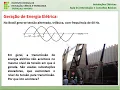
Brazilian system as a whole in terms of generation and transmission. Based on what we've discussed so far, we know that in Brazil, three-phase alternating current is generated at a frequency of 60 Hz. However, the transmission of electrical energy generally doesn't occur at the same voltage level as the generation. Step-up substations are used to increase the transmission voltage level . Do you know why this happens? Well, right after the generator in the power plant, there's a transformer that we call a step-up transformer. It's responsible for taking the generation voltage level, which is usually around 13,800 V,
and increasing it to much higher voltage levels, such as 500,000 V or 750,000 V. What's the reason? Why does this happen? This happens basically due to losses in the transmission process. The voltage increase aims to reduce losses. Think about it: for a constant power, when we increase the voltage, we consequently decrease the current. So, with this process of increasing the voltage, we can reduce the current level. And when we think about losses, remember that losses, power dissipated by a conductor , can be calculated as R x i²? Losses depend on the square of the current.
So , when we reduce the current, the transmission level, we can considerably reduce losses. That's why transmission happens at this high voltage level. This is how we can guarantee feasible sizes for the cross-section of the conductors that will be used for transmission. And in this way, we also reduce losses. Where is the transformer ? The transformer is usually not alone; it's located in a substation. So I've included some representative figures of substations. These substations are not only made up of the transformer. There are several other electrical equipment that also make up this location. What are
the functions of substations? Well, a first function we can think of is the one we talked about regarding the transformer. It's to transform the voltage level up or down. In this case, since we are moving away from the generation process, the substation we are talking about now is a step-up substation, which will increase the voltage level. Besides this transformation function, we also have a protection function. There are protection devices to maintain the safety of the electrical system's operation. The substation has switching devices. If the need arises to open or close part of the circuit, we
have this possibility with the substation through the switches. And in addition, we could mention another function of the substation, which is to compensate for reactive power. So, substations are these places that have various types of equipment with various purposes. I've included some figures. These first two show substations that you have certainly seen at some point in your life, which is an air-insulated substation. It uses air as its electrical conductor, which is why it is generally a larger substation and the equipment must maintain a distance between them, because if an electric arc occurs, the air is
used to extinguish the arc. So, we have to position the equipment correctly, ensuring a safe distance between the components. There are other types of substations that use other electrical elements, such as the SF6-insulated substation, which is the image I've included below. What are the advantages of these substations? They occupy much less space because the electrical efficiency of SF6 is much higher than that of air. Therefore, I can reduce the size occupied by the substation. SF6 is sulfur hexafluoride. Although it has excellent electrical properties, this gas has some environmental problems because it is a major contributor
to the greenhouse effect. Currently, the electrical equipment industry is looking for alternative solutions to the use of SF6 that are efficient electrically but do not harm the environment. Now we will continue this discussion by talking about electrical power transmission. So, we've already generated the energy, it's already passed through a substation, the transformer has already raised that voltage to transmission levels, and now is the moment when it will actually travel through the power transmission lines. Okay, so let's look at some aspects related to this transmission process. Here I've included another figure that I took from the
NS website, which is about the panorama of electricity transmission in Brazil, with a comparison between the years 2019 and the forecast for 2024. So, you see, we have the extent of lines we have in Brazil for each of the different voltage levels. Note that below, the lowest transmission voltage level shown is 230 kV, or 230,000 V. And then it increases up to our maximum transmission level, which is currently 800 kV. Most of the transmission lines in Brazil are alternating current. We currently only have four direct current transmission lines. The direct current transmission lines are at
a voltage level of 600 kV, as you can see here. It's 600 kV DC. This DC indicates direct current. And we also have 800 kV DC here, also direct current. All the other lines are alternating current. Looking at the comparison between 2019 and 2024, we see that these first three lines here do not change. And from here on, from 500 kV downwards, all these lines are projected to increase over these years. It's important to tell you that this voltage level of 800 kV for direct current transmission lines is quite recent. Our maximum transmission level previously
was 700 kV in alternating current, now we have 800 kV in direct current. This came from the Belo Monte hydroelectric plant. So, we have two 800 kV direct current transmission lines that come from the state of Pará, from the Belo Monte plant, and go to the Southeast region. One of them comes here to the state of Minas Gerais, uh, in Estreito, Minas Gerais. And the other one comes from Belo Monte and goes to the metropolitan region of Rio de Janeiro. So, we have these two new 800 kV lines. These 600 kV lines are also two
that we have of 600 kV DC. We have one that connects Porto Velho to Araraquara and we have another that connects Foz do Iguaçu to Ibiúna. So, apart from these four lines, two of 600 kV and two of 800 kV, all the others are AC. What does that mean? What are the terms, the factors that should be taken into consideration when opting for the construction of an alternating current or direct current line? Generally, the factor that carries the most weight is the length of the line. In addition, other factors should be taken into consideration, such
as the structure, the number of conductors, the location where it is, and so on. Well, now there are other situations where direct current lines can be useful, such as the one I mentioned, from Foz do Iguaçu to Ibiúa. This line from Foz do Iguaçu originates from the Taipu hydroelectric power plant. There, we buy energy from Paraguay, but Paraguay generates energy at 50 Hz, not 60. The Paraguayan electrical grid is 50 Hz. So, what do we do? We can't use this 50 Hz energy coming directly from there here in Brazil. So, what was done in Foz
do Iguaçu? There's a station we call a rectifier. It takes this energy generated at 50 Hz and converts it to 0 Hz, that is, it converts it to direct current. It then travels along the direct current transmission line at a frequency of 0 Hz. When it arrives in Ibuá, the inversion is made, and it ceases to be direct current and becomes alternating current at 60 Hz for use here in Brazil. So this is also a possibility when we have to change the frequency. Nothing would prevent, it is also physically possible, from having the rectifier and
inverter station at the same point. It would also be possible if the option were to do the rectification and inversion to 60 Hz there in Foz do Iguaçu itself. It is possible, but in this case, the option was to use direct current transmission. I have included another figure here that I also took from the NS website, which shows us the 2024 horizon in terms of electricity transmission. So here we can see all the transmission lines in our country. You can observe here, looking at the legend, that as we said, most of our lines are alternating
current (AC) and voltage. We have a minority of direct current lines. Note here that our maximum transmission level is 800 kV, which are those newer lines I mentioned to you, right? DC lines. And in terms of alternating current, our maximum transmission level in this timeframe is 750 kV. I repeat that if you are interested, go to the website [website name], which has a lot of interesting information about this overview of our interconnected system in terms of generation and transmission . We will now talk about the distribution of electricity in Brazil. As I told you, the
organization responsible for distribution is no longer the ONS [National Electricity Regulatory Agency]. Now we will talk about ANEEL, which is the National Agency of Electric Energy. How does ANEEL define electricity distribution for us? Let's read here. Distribution is characterized as the segment of the electricity sector dedicated to delivering electricity to an end user. As a general rule, the distribution system can be considered as a set of electrical installations and equipment that generally operate at voltages below 230 kV, including low-voltage systems. So, regarding high, medium, and low voltage, what ANE (Brazilian National Agency for Energy) considers
for distribution systems is the following: high-voltage distribution is between 69 kV and 230 kV. Medium-voltage distribution is between 1 kV and 69 kV, and low-voltage distribution is less than 1 kV, that is , less than 1000 V. As we've already discussed transmission, going back to the idea of the energy's journey, we now move to the distribution level. To pass through the distribution level, we need another substation. So this shows an open, air-insulated substation. And here we can consider that in this substation there is a transformer. And this power transformer is a high-power transformer, right? We
are still working with high levels of electrical power. Well, then the high voltage, the voltage that came from the energy transmission level, arrives at this substation. And this transformer is a step-down transformer. So, it will reduce the voltage level coming from transmission, for example, here 138 kV, to the medium voltage level, which is the distribution level. In our region, this level is 13.8 kV, 13800 V. So, the step-down transformer here in the substation does this conversion, and now we have medium voltage that will flow through the distribution networks. As we mentioned, it's not just the
transformer that exists here in the substation. The substation is made up of several components: protection components, such as circuit breakers; network switching components, such as switches; the conductors themselves; insulators; in short, it's a set of equipment with these functions that we discussed earlier. Now I'll show you the secondary network in this figure. So, in this case, observe in the figure , this is a very common image that we see everywhere in the city, we have the primary network above. This primary network here is neither in compact form nor in isolated form, it's in the form
of bare cables. So, it's a network that operates at medium voltage in our region, 13,800 V. It enters the primary side of the transformer. From the secondary side, the secondary network will emerge. So here we have the low-voltage circuit, which in our case transforms to 127-220 V. 127 is the phase-to-neutral voltage, 220 is the phase-to-phase voltage of this secondary network. Here, if you observe , in this case, we have three phases in the medium voltage and three phases plus the neutral in the low voltage, because we are considering that this transformer has a delta-star connection
. So here in the primary we have the delta connection, so we have the three phases. Here in the secondary, with the star connection, the neutral also appears, which must be grounded here at the distribution pole. In this way, we have now finished understanding the entire process of energy travel from generation to our end consumer. So, understand that our discipline will focus on analyzing the installation. We will learn how to design the installation here, specifically for this end consumer of this low-voltage installation. To help you better understand all the steps we discussed earlier about how
a hydroelectric power plant generates electricity, how a synchronous generator works, the operating principle of a transformer, and if you want to know about the equipment, the main aspects that constitute transmission and distribution systems, and the materials used, you can understand all of this in more detail in this video that I'm leaving here in the card as supplementary material for you, okay? So, from now on, in today's lesson, we're going to focus on low-voltage electrical installations themselves. Now we'll talk about the NBR5410 standard. The Brazilian standard ABNT NBR 5410 is titled "Low-Voltage Electrical Installations" and its
latest version was published in 2004. So, you can see that the latest version is relatively old, and there's a forecast for updates in the coming years. The objective of this standard —this I took from the standard itself , okay? That's why it's in quotation marks. This standard establishes the conditions that low-voltage electrical installations must meet in order to guarantee the safety of people and animals, the proper functioning of the installation, and the preservation of property. Application. Where does this standard apply? This standard applies mainly to electrical installations in buildings, whatever their use, whether residential, commercial,
public, industrial, service, agricultural, farm , etc., including prefabricated buildings. So, this standard, folks, will be the standard we will use from today until the last day of our electrical installations course, because our focus in this course is precisely to study and design a low-voltage electrical installation. We will not deal with high or medium voltage installations. Our focus is at the distribution level with low-voltage electrical installations. That is why this standard is so important to us, and we will study it extensively. Generally speaking, the standard applies to electrical circuits powered by a nominal voltage equal to
or less than 1000 V in alternating current with frequencies less than 400 Hz or 1500 V in direct current. For a more detailed explanation of the conditions to which this standard applies and does not apply, it is recommended to read item one. So I suggest you take the standard , read the introduction, item number one, to understand where it can be applied and where it cannot. After that , we can ask ourselves how a low-voltage electrical installation can be powered. I will tell you four ways in which low-voltage installations can be powered. Number one is
directly from a low-voltage electrical distribution network via a branch connection. This is the typical case for residential, commercial, or even small-scale industrial buildings. This figure helps us understand this type of power supply . Notice that we have several installations here, several residences, in this case, we can think of them as being supplied from branch lines that come from the same transformer in the distribution network. So the same transformer can supply several different installations. This is what we generally see in these smaller buildings. Your house, if you look at how it receives energy, will probably be
like this: there will be a transformer on the distribution pole. From that transformer, several branch lines will connect your house and some of your neighbors 'houses. The second way we have here is through a high or medium voltage distribution network via a substation or a dedicated transformer owned by the utility company. This is the typical case for residential installations for collective use, apartments, buildings, and large commercial installations. In this case, since our installation is larger than the previous one, we will need a dedicated transformer, that is, a transformer that will supply only this installation. So,
if you live, for example, in a building, a large apartment, there might be a transformer owned by the utility company, whose sole purpose is to supply power to your building's installation, right, to your apartment. This happens for installations that are, logically, larger than in the previous case. Note that here the transformer is exclusive to this installation, but as we read here, it is still owned by the utility company. It belongs to the utility company and supplies only a medium-sized installation, larger than in the previous case. Now we have the third possibility, which is a high
or medium voltage distribution network through a substation owned by the consumer. So this case is typical for medium and large-sized industrial and commercial buildings. So, what is the difference between this third case and the second case? In the third case, in general, we will have larger installations, and the substation, transformer, and all the substation equipment are owned by the consumer. The consumer buys it and is responsible for maintaining all this equipment. The utility company will deliver the power to the consumer at this voltage, in terms of high or medium distribution voltage. From there, the consumer
is responsible for all the processes of lowering the voltage, implementing the entire substation protection system; it's all the consumer's responsibility. Finally, we have a fourth possibility, which is an autonomous source. This is the case for security installations or installations located outside areas served by utility companies, where the generation source belongs to the consumer. In this case, the consumer is not connected to the utility company's grid. They have their own generation source, like in this figure here, which represents an example of a consumer with a photovoltaic panel. They generate the energy they will use in the
installation. The figure shows the battery bank for storing energy. And in this case, the entire consumer operates from the supply of this autonomous source. Generally, we see many examples of hybrid power supply, where a consumer is connected to the utility company's power grid, but also has an autonomous source so as not to depend solely on their own power supply. This is another possibility. You might be wondering how we determine the type of power supply a given installation will receive. So, among the types we discussed earlier, how do we know which installation will receive which type
of power supply? This depends on the requirements imposed by the utility company. The following factors are taken into consideration: installed power, demand, and the presence of certain specific types of loads. Let's define each of these terms a little better. We consider installed power. What is installed power? It's the sum of the nominal power ratings of the electrical equipment in a consumer unit , which, after the installation work is completed, will be ready to operate. Let's imagine the example of a house, which makes it easier to understand these concepts. Okay, so to calculate the installed power
in a residence, all you need to do is add up the nominal power of all the equipment that can be used in that residence. So we're going to add up the power of the light bulbs, the outlets, the general-purpose equipment, the specific-purpose equipment, and we'll see what that total sum is in terms of power. That's the installed power of the residence. Now, another very important term is demand. What is demand? Demand is the average of the instantaneous electrical power requested by a consumer unit during a specified period. To understand demand, think about it this way:
when we do this summation to obtain the installed power, we realize that this is an important number, right ? It gives us some information, but it doesn't accurately characterize the operation of the installation at all times, because we know that not all the light bulbs are on and not all the outlets are being used all the time. So demand serves precisely to give us this idea of the average instantaneous electrical power requested by the installation in a specific period. Demand is very important. We, as residential consumers in our homes, are not charged for energy based
on demand by the utility company. However, some types of consumers, large-scale consumers, type A consumers, may even have their energy tariffs modified depending on the demand value, because demand can be thought of as instantaneous electrical power, right? So, it's the effort that this installation requires from the grid in a specific period of time. For us, I repeat, residential consumers, this demand value does not influence our final energy bill, but it will influence, as we are saying here, the type of power supply that our installation will receive. Finally, the presence of some specific types of loads.
There are some types of equipment and loads that require certain characteristics and special care. So, depending on the presence or absence of these types of loads, the utility company may define the type of power supply based on this, right? It takes this into consideration as well. What are some examples of these specific types of loads? Motors, welding machines, and high-power single-phase loads, for example. So, each utility company in each region of the country will take these factors into account to define its rules regarding the type of power supply each consumer will receive. In a few
lessons , in lesson number five of our course, we will study the rules of SEMIG, which is the region where we are. We will see what SEMIG defines based on these concepts of installed power, demand, and the presence of specific types of loads to determine what type of power supply a consumer will receive. Now, in this figure, we will discuss some very common terms used in electrical installations. The first thing that is important for you to understand is that we are talking about low-voltage electrical installations with direct low-voltage input. So, imagine that type of power
supply number one, to make it easier, imagine it's a residence, a house with a transformer that's on the pole, several connection branches come out, and one of those branches comes to your house, to the house we are imagining. So let's look at the terms we use to identify each of these parts of the installation. Here we have the secondary electrical power network, already at low voltage. Let's imagine this as the secondary of the transformer, which has a voltage in our region. Phase-to-neutral voltage 127 V. Phase-to-phase voltage 220 V. So don't say 110 220. That doesn't
exist in our region. It's 127 220. 220 is the phase-to-phase voltage. 127 is the phase-to-neutral voltage. Right? Well, here we have the branch point. This is the point where the branching actually happens. Several connection branches come out. This connection branch, then, here, it will come out of the secondary network and reach this point here, which is the delivery point. So, this entire length here, from the branch point to the delivery point, we call the connection branch. What is the delivery point? The delivery point is the point up to which the utility company must supply energy.
And up to that point, it participates in the necessary investments and is responsible for the execution of services, operation, and maintenance. This delivery point is not necessarily the metering point. The metering point will be here in front, here at the metering panel. The delivery point, then, is the point from which the responsibility for the installation passes to the consumer. Up to this point, the utility company is responsible for everything: operation, maintenance, etc. It is from the delivery point that we will study and apply NBR5410 to define the low-voltage installation requirements that we will use throughout
the course, right? So this is our delivery point. What else do we have from the delivery point to here? This incoming panel, we call the service entrance. Note that there is a very strong similarity between what we call the service entrance and what we call the consumer's service entrance. The service entrance connects the delivery point to the distribution panel, excluding the panel itself. The consumer service entrance connects the delivery point to the distribution panel, including the panel. This is the terminology we generally use. Now, this entire region here, the whole set of equipment, conductors, and
accessories that exist here, from the branch point to the distribution panel, including the panel, is what we call the service entrance of the installation. Okay? In this panel here, the entrance panel, we observe the existence of protection devices to protect the installation, the electrical system, and we also observe the existence of metering devices, which is where the utility company installs the meter to account for the total amount of energy the consumer is using. I took these figures from Cotrimá's book in our bibliography. Well, here is another representation of a low-voltage installation with a direct low-voltage
service entrance. So, here it shows in this figure, from the delivery point, the origin of the installation for the consumer, the point from which the consumer is responsible. And here we have the service entrance, we have the meter box. Inside the meter box, we have a meter and a protection device. Although the figure shows a fuse, which we currently use inside the meter box, especially for this residential case we're talking about, it's a circuit breaker, the protection device we use. So, after passing through the meter and the general protection, we have what we call the
distribution circuit. This distribution circuit connects, let's say, the entrance of the installation, this meter box, to a panel. And in this case, we are working with a terminal panel. We are considering that it is a small-scale installation, a house. So, the distribution circuit arrives here at the terminal panel, and from the terminal panel, several circuits come out, which we call terminal circuits, as the name suggests, they are circuits that are at the end of the installation . So, they are the ones that will supply our final loads, lamps and sockets, in the case of a
residence. So , inside the terminal panel, we have protective devices, circuit breakers, to protect each of our circuits that will power our loads. Another possibility is shown here regarding a low-voltage installation that doesn't receive low-voltage power; it has a high-voltage input. So, with this high-voltage input, let's imagine not a small installation, but a larger one, like an industrial installation. So, we have our delivery point here, the incoming branch. Here at the beginning, we have a protective device. Depending on the size of the installation, we will have to design the appropriate incoming protection device for each
type of installation. We have the transformer here. The transformer is the equipment, as we know, responsible for changing the voltage levels. And then we'll follow the measurement process. This is the meter. In larger installations, the meter may not measure directly at the installation itself. We may need transformers, which we call PTs and CTs. If the voltage level is too high, the meter isn't placed directly at that high voltage level. We use a potential transformer ( PT) to lower the voltage before taking a measurement. The same applies to current. The meter isn't connected directly to a
very high current level. We need a current transformer (CT) to lower the current level. As shown in the figure, a PT wasn't used. Here, the voltage level was already low. In this case, in this figure, it was considered that a PT wasn't necessary. There is a CT here because the current level passing through here, if the installation is large, is very high and the meter can't handle it. So we use a small current transformer; it reduces the current level, and then this current passes through the meter, and the meter counts how much energy the installation
is consuming. Furthermore, another detail I wanted to show you that differentiates a small installation from a large one is the number of electrical panels. In the previous screen you saw that we had only one terminal panel. The distribution circuit connected the meter, the point where the measurement was taken, to a panel, and from that single panel the terminal circuits came out. When we have a larger installation , other panels may be necessary. So, notice that in this example we have two distribution panels and at the end here a panel that he called the terminal panel.
So, this distribution panel has its protection devices and its circuits . From one panel it goes to another panel. We have here, the main distribution circuit. It arrives here at another distribution panel. We have its circuits here, a protection device. And from here we have another circuit that he called the visionary distribution circuit. And this circuit then comes here to the terminal panel, which is where the protection device is also located, and the terminal circuits come out here. So, depending on the size of the installation, folks, there won't just be three panels, as shown here.
There may be several other panels . Another detail is about the protection devices. In residential installations, circuit breakers are used for overcurrent protection. We will discuss the protection devices used in residential environments in lesson four. Now, in this example, in the figure, you can see that fuses are also being used within these panels, because in industrial environments, depending on the type of load, fuses may be used for overcurrent protection, for example, some types of motors, and we use fuses. So, depending on the size , scale, and type of installation, the entire configuration changes. And I
wanted to show you these two figures that I took from Cotrm, from the Cotrm book, so you have a general idea about the installation inputs. In this subject, we will focus on learning how to design a low-voltage electrical installation. So, in general, to give you an idea, I will then point out some steps in this design process that we will follow. So, number one is the initial analysis. In this step, what does the designer do? The designer will get to know the installation they will be working on better. So, what is part of this first
stage? The designer has to determine the type of installation; they have to identify the planned equipment; if there is any type of special load that will be installed in this location; the type of electrical line that will be used; if there is a need for any type of emergency lighting ; if there is any type of security equipment that will be installed. So, ideally, if possible, the designer should also get to know the client, their needs, desires, and expectations, in order to then have a general, initial idea of how this project will proceed. After this
initial part of gathering these characteristics, we can move on to phase number two, which refers to defining the power supply. So , in this stage, the designer must define, according to the rules of the local utility company, what type of power supply will be used from those types we discussed earlier in this lesson. So, for this, the characteristics of the installed load and demand will be determined, and the distribution rules of the local utility company will be studied to define the type of power supply and its characteristics that the utility company will provide to this
consumer. Then, in step three, we can move on to quantifying the installations. In this stage, the designer will have to determine values and quantities. They will have to perform calculations to accurately design all the characteristics of the installation. For example, going back to the example of a residence, the designer needs to perform the lighting calculations to determine the ideal number of lamps that should be present in each room, as well as outlets—general-purpose outlets, specific-purpose outlets. They must determine the load center of the installation. So, all these definition and quantification processes must be done in this
stage. When we move on to step four, we will create the basic installation diagram. We will use technical language and electrical installation symbols to create this basic diagram. In our course, we're going to learn how to do this with AutoCAD, but obviously, AutoCAD isn't the only software used for electrical installations. There are other software programs, including specific software for this purpose. So, based on the definitions made previously, using software, the designer will use technical language to indicate all the connections that will be made to make this installation work. After that, we have number five, component
selection and dimensioning. So, the designer will have to list all the components that are necessary to make that installation . Some of these, along with item number six, which is specifying and counting the components. Some of these components are quite easy to imagine. For example, you have to buy the distribution panel that goes inside the house, you have to buy the circuit breaker, the RCD, the surge protector, all the conductors, the conduits, all the switches, and sockets that will be used. Everything has to be specified in the project, regarding the type and count. Some components
require more care. For example, to properly specify a protective device, a circuit breaker, you need to know the maximum short-circuit level that can occur in that installation. Therefore, the designer must take all precautions to specify it completely and adequately. They will have to calculate the short-circuit level, for example, and a number of other requirements to make the correct sizing and specifications. So, with item number six, after having done all the schematics, in terms of calculation, in terms of representation with technical language, we specify these components and then we finish the installation project. Regarding the graphic
symbols that we generally use in installation projects, I will show you some of the most commonly used symbols. And these symbols refer to NBR544, a fairly old standard that deals with symbology for electrical design. Okay, we're not obligated to follow these symbols exactly, but it's recommended that we follow this same structure, this same way of drawing, because that's what's used professionally and technically in electrical projects, but some adaptations are possible. For example, if we look at the first symbol here, it's for an incandescent light fixture on the ceiling, right? An incandescent bulb. We don't even
use incandescent bulbs anymore. So you can, if you want, replace that symbol with an LED light fixture on the ceiling, right? Where will you have to make that clear in your project? In the legend. Every project has a legend. So, in the legend you will always put the symbol and next to it a very clear description of what you are using that symbol for, right? So we have that freedom, although it's always recommended to more or less follow these drawings as they are normally used. So here are several possibilities. This second one would be an
incandescent light fixture on the wall, right? Wall sconce, recessed incandescent ceiling light, recessed fluorescent ceiling light, wall fluorescent light, and recessed ceiling fluorescent light. This one you can use , for example, for a tubular fluorescent lamp, right? So you have to , I repeat, make everything very clear, well described in your legend. These letters that are appearing here, C, R, P, are important information that will have to be in your project, right? C is the circuit number, R refers to the return, which will identify which switch will activate which lamp. And P is the power
of this light point. But we will learn this carefully and in detail when the time comes to do this in our project. Here now I have the representation of some types of switches. So we have here a single-section switch, a double-section switch, a three-section switch. Here we have these three, which are simple switches, which we call the first three . Here we have the parallel switch, the intermediate switch, we have the symbol for a timer button, a doorbell button. So, uh, these, the function of these switches, the difference between them, we'll also learn in a
few weeks. Outlets. What symbols do we use to represent outlets? Outlets are usually represented by symbols with these triangles. As you can see, the triangle without an angle, half-angled, or fully angled, serves to indicate the height of the outlet. So, a low outlet is usually without an angle, a medium outlet is half-angled, and a high outlet is fully angled. We have other possibilities here, such as floor outlets and doorbells. Regarding the types of conduits, the one we will use most in our project is this continuous line here, which is the conduit embedded in the ceiling
or wall. If you are going to make a conduit embedded in the floor, you have to change the symbol. So, you can use stress here. We have piping for external and internal telephones, piping for doorbells, intercoms, sound systems, or other systems. And below we have the symbols that we usually use to represent the types of conductors. We have phase conductor, neutral conductor, return conductor, and protective conductor. Each of these conductors will be represented with a different symbol. So , this first one here is what we use for the phase. This second one is what we
use for the neutral. This little line here looks like the phase, but it's only on the top part here. This third one is the return. And this little T here is what we use for protection, to indicate the protective earth conductor. Junction boxes. We have here a junction box in the floor, a junction box in the ceiling, a junction box in the wall. We have the symbol for the remaining circuit and the descending circuit. In the case of installations with more than one floor, we have the panels here. Surface-mounted light and power terminal panel, recessed
light and power terminal panel in the wall, surface-mounted main panel and recessed main panel. And we also have the telephone box down here. Here, just so you have an idea, is an example of a part of a project being developed in AutoCAD. So you will receive a blueprint, and from that blueprint you will perform all the calculations to reach the final stage of a complete project, right, with the routing and specification of all the components of this installation. Well, everyone, that's what I wanted to tell you in today's lesson, in this introductory lesson. I hope
you understood, and I am available to answer any questions that may arise. Thank you for your attention , and until next time. M.