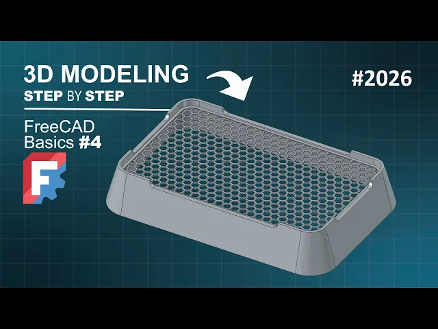
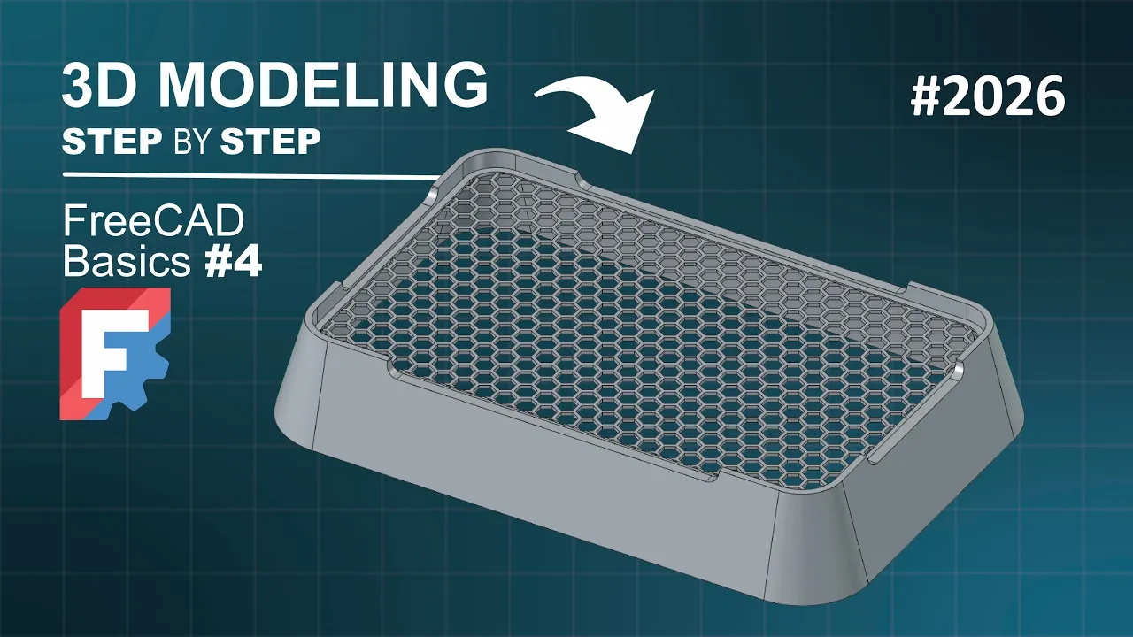
In this video number four of the FreeCAD Basics series, I will show a step-by-step process of how we can build a 3D model using a single sketch. Something that is not possible in the new and the recent version of FreeCAD, the FreeCAD 1. 1.
The entire process will take place in the Part Design workbench, highlighting the thickness, linear pattern, multi-transform, and Boolean tools. I will start the modeling in a blank document. I will save it as model four.
I will create a body object by pressing the new body icon. I will create a sketch by pressing the new sketch icon. And I will attach the sketch to the XY plane.
Here I am with the sketch open in the Sketcher workbench. What I will do here is create all the geometry needed for operations like extrude and pocket. I will start by creating two hexagonal geometries, which I will later use to generate this hexagonal grid.
Then I will create the geometries for the main shape of the object. Finally, I will create the geometries for these pockets. I will go to Sketcher geometries, expand triangle tools, select hexagon, and then create two hexagonal geometries like this.
Next, I will make this line a vertical line by going to Sketcher constraints, expand these tools, and select vertical constraint. Next, I will select these two construction circles and make them equal. Next, I will select the dimension tool, click on this circle, and set it a amount of 6 mm.
I will skip the tool, and then I will drag these geometries, and I will change the geometries to construction geometries by pressing this icon. I will select the line tool, and I will pick the mid of this line and the mid of this line here, and create a base construction line. Change back to normal geometries, and in the Sketcher constraints, I will select perpendicular constraint, and make these two lines perpendicular.
Next, I will select parallel, and make these two lines parallel. Next, I will select the dimension tool, and set the length for this construction line, which is 1 mm. And I have the geometry full constrained, as you can see.
The next thing that I will do in these two geometries is to create two reference dimensions that I will later use to define uniform spacing between the holes. And to do that, the first thing that I will do is to hide these all constraints by pressing this icon. Next, I will go to Sketcher constraints, and change the dimensions to reference by pressing this icon.
And next, I will select the dimension tool again, click on this center point, and next in this one, and create a horizontal distance. Select this center point and this one here, and create a vertical distance. I will skip the tool, and change to normal dimensions.
And the next thing that I will do is to set names for these two reference dimensions. I will double-click on this dimension, and set name. The name will be width.
Enter. And this one here, the name will be height. And I will hide these constraints here by pressing this I icon two times.
The next thing that I will do is to go to the Sketcher geometries, and select the polyline tool, and create these two lines here. Fillet it, and next I will create a fillet here on this corner. I will skip the tool, and then I will select this point, and delete it because I don't need it on this geometry.
Next, I will select this geometry in this way, and I will create copies, two copies of this geometry. Control C, and now control V. And next, I will move this geometry.
I will select the geometry again, control C and control V, and I dropped the geometry. Next, I will select the polyline tool from the Sketcher geometries, and try to close this geometry. I will skip the tool, and the next I will apply some vertical and horizontal constraints for these lines here.
I will start by selecting this line, this one here, and this, and I will make them vertical. Next, this line here, this one, and this, I will make them horizontal. Next, I will select this line here, this one here, and this, and this, and make them equal because they have the same width.
Next, I will select the dimension tool. I will start by setting the radius of this arc here to 12 mm. This one here to 10 mm, and this to 8 mm.
Next, I will select this line here, click off, and I will set 2 mm for the length. I will skip the tool, zoom in, and drag this point to select the two points in this way, and make them coincident. Two degrees of freedom, as you can see.
The next thing that I will do is to set a height and width of this geometry. So, I will start by selecting the dimension tool again. Next, I will click on this line here, and the horizontal axis.
50 mm. And from the vertical axis to this line here, the distance will be 8 mm. I will hide these all constraints.
And now, I will select a center rectangle from Sketcher geometries, and start the first geometry in this point, 100 mm by 12 mm. And now, on this point here, I will create another rectangular geometry. 12 mm by 50 mm, and I have a full constrained geometry.
I will skip the tool, and then hide these all constraints. And as you can see, I created geometry that represents a quarter of this 3D model. The reason is that I don't need to create a full geometry because of the symmetry of the part.
I will close the sketch. And next, I will try to center the sketch on the 3D view. For this sketch, FreeCAD generated only three faces.
It was not exactly what I expected, but I can still move forward since the workbench allows extruding fully closed geometries. I just need to select the closest set of geometries, and use the commands. So, I will start by increasing the size of the lines and points of the sketch here.
I will select a sketch on the 3D view, and go to its properties. Change the line width to 2 mm, and the point size to three. And select a top view.
I will start by selecting this line here, next this arc, this line, this line here, and this one. And now, to close the geometry, the solution, I will select this line, this one here, and next, this, and this. And click on the pad tool icon.
And now, I will press home. And the first thing that I will do in the pad parameters is to reverse the direction, 40 mm for the length, and then I will press okay. The next thing that I will do on this model is to apply a draft result feature.
So, I will select this face, hold the control key, and this face, this one. And click on the draft result feature. And in the draft parameters, the first thing that I will do is to set a neutral plane, which will be this face here.
I will click on this button, and then select this face. And change the angle to 15 degrees, click off, and then okay. The next thing that I will do is to add thickness to this object.
So, I will start by selecting this top face, hold the control key, and this face. This one, and this one here, and click on thickness. 1.
75 mm, and then I press okay. The next thing that I will do is to create another extrusion. I will start by expanding the tree of the first pad feature, and make the sketch, the first sketch visible.
And now, I will hide the thickness feature. I will change to top. I will select this edge.
This one, this edge, this, this, and this one here. And to close the geometry, I will select this edge. And next, this edge here, and I will click on the pad feature.
I will reverse the direction of this extrusion by checking this option. And the length will be 6 mm. If I change to the front view, as you can see, I have this.
I will press okay to finish this. And And next, I will create pockets on this model. To do that, I will make the first sketch visible by pressing this icon, or by selecting the sketch, and press spacebar.
Okay, to create the pockets, I will start by selecting these rectangular geometries. So, I will select this line. Next, this one, this one, and this line.
And now, pocket feature. 5 mm. I will press okay.
And next, I will select this edge, rotate the view, and select this edge here, and create a fillet here. 3. 5 mm, and okay.
Now, it's time to create a new body object. In this new body object, I will copy the sketch from the first body, and move it 60 mm down. The reason I need another body with the same sketch is this hexagonal grid.
To create it, the holes must not go beyond this edge. Another reason is the grid starts early lower. So, I will press the new body command icon.
I will expand the tree of the first body object, select the sketch, control C, and now click in user region selection. Control V to paste the sketch on the document. Now, I drag the sketch into the body 001 and space bar to make it visible.
Next, I will select the body 001 on the tree view and go to its properties. I will go to data and change the placement on the Z position minus 5 mm. I will select this pocket and change the length to 4 mm, which is the correct length.
Now, it's time to create an extrusion of this geometry. And to do that, I will change to top. I will select this edge, hold the control key, and select this edge next to this edge and this one and this.
As you can see, I have a closed geometry. I will use this to create the first extrusion on the body 001. I will click on the pad feature.
I will reverse the duration and I will set 1 mm for the length of this extrusion. Press okay to finish the pad parameters. I will zoom in and select this face here and create a small chamfer.
0. 5 mm and then okay. And now that I have this, it's time to create the first holes using the hexagonal geometries.
To do that, I will go to the body 001, expand the tree of the first pad feature, and make the sketch visible. Space bar. And here, what I have to do is to select these three faces and use them to create a pocket.
I will hold the control key and select this face here, and next to this face, and this one here, and click on the pocket feature. And as you can see here, I have a preview of the pocket. I will just press okay and I have the first holes.
The next thing that I will do is to create a linear pattern of these holes in the Y and X direction. I will select the pocket 001, the last feature of the body 001, and click in linear pattern feature. I will change to top view.
And here, for the first duration, I will change I will change it to X and the mode to spacing. In the spacing, I will place a formula. I will call the expression editor pressing this icon.
And here, I will type sketch and I will select the sketch 001, this sketch here, and then select constraints. As you can see here, I have these two dimensions. The correct is width for the X direction multiplied by two.
As you can see, the result is 6. 2 mm. I will press okay.
I will add a second duration checking this option. I will change the duration to Y axis and then the mode to spacing. And for the spacing, I will place an expression.
I will call the expression editor and here I will type sketch and select the sketch 001 constraints and height multiplied by two and the result is 10. 73. As you can see, I will press okay.
And next, I will change the occurrences to two and press okay. To increase the holes, I will select the linear pattern and go to its properties. For the duration two, I will set six occurrences.
For the first duration, I will increase to 13. As you can see here, I have the grid and the next thing that I will do is to fill this space here. To do that, I will create another extrusion.
I will make the sketch visible and I will change to top view. I will hide the first body and I will zoom in here, select this edge, this edge, and this one, and next this edge, this edge, and this, and now this edge, and this edge. Now, I click in the pad feature.
Okay, I will reverse the duration and set the length of 1 mm for this extrusion and then okay. If I make the first body visible, as you can see, the result is this. Now that I have completed this half, I will create the others to finish the freedom model.
But before that, I need to merge the second body with the first one. And to do that, the first thing that I have to do is to make the first body active. Double click.
And next, with the first body selected, I will go to Boolean operations command icon. And here, I will add a body. I will press add body and select the body 001.
And as you can see, I have this result. I will press okay. Okay, as you can see, the second body is now a child of the first.
Next, I will finalize this freedom model using the multi-transform tool. I will select the body object, not the operations, the body object, and go to multi-transform feature. I will go to transformations and right click and then select add mirror transformation.
I will change the plane parameter here to YZ plane. And then okay. I will add another mirror transformation.
This time, I will change the plane to XZ plane. And okay. Okay.
So, this is the final model. Thank you for watching this video. If you find this video useful, please don't forget to hit like and share this video with your friends.