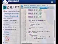
We are at module 41now; module 41 is going to be on the GCD machine. So, we have notstill decided or design the state machine we had the picture, but we have not written it to the Verilog here. So, in this module, we willgo, we willlook at how to write Verilog module for this state machine.
So, let us look at the state machine,let us look at the picture here So, we have a state machine here, which has these7 states,8 states S naught, S 1, S 2, S 3 up to S 7 and in this, what we have done is, you have said clock is never part of these state diagram itself. So, we do not have it and we said,this is the reset state. So, again just to quickly recap, sowe will wait for a go signal from the external world, till themwe will stay at S naught.
If the go signal comes, then we are ready to load the inputs from the external world. So, to do that, wewill setup all these signals to be 1, we will delay by one clock cycle, sothat the results areready in the register. Once,the results are ready in the register at S 2, at S 3 the comparative will be able to give a study output; we will check the comparative results.
Based on the comparative results We go will go to either S 4,S 5 or S 7. If you are in S 4 or S 5, GCB is not complete, so wewill put the results from either the state,either the register a or the register b back in to the circuit itself through the data path and will come backto the S 3 and start comparing. So, S 6 is again a wait state, at S 4 or S 5 we will… So, we atS 4 and S 5, we will set up insuch a way thateither a gets updated or b gets updated.
If you are in S 7,we know the job is done and we can go and wait for new inputs. So, this is the state diagram that we had and in terms of a block diagram,we saw this. So, we have clock reset, go, which are inputs, then there are 3 inputs from the data path,4 outputs with the data path,one more output called the output enable and the done signal, sothis is what we want over all.
So, what I want to do now is,connect it back to something that is familiar to you. So, remember we talked about the notion of a canonical state machine. So, the canonical state machine is something that we did inone of the earlier classes, soI want to connect it back to that.
So, let us see how a canonical state machine was supposed to be. We said a canonical state machinemust be of this form. So, we had a state register andthe output of the state register must be connected to, what is called the output forming logic and from where the outputs come through and there was somethingcalled the next state logic or the input forming logic that gives to thestate register.
So, the state registers also feats the input forming logic and there are primary inputs that are spread both to the output forming logic as well as the… So, these are the primary inputs, sothis is the canonical picture of the state machine. Now, for our state machine we should figure out, what the variousinputs and other things are. So, again let us look at this picture, if you notice go, then a greater than b, a less than b,a equal to b,these are all inputscoming into the state machine.
So, we will mark them here,go and a greater than b,a equal to b,a less than b, these are the supposed to be inputs to thecontroller itself. The output of the controller could be done, the done signal itself comes from here. Then, we had things like a select, b select, a load and b load, these are all supposed to be outputscoming from the controller and besides this if you notice, there are two wires that are unnamed or two bunches of wires that are unnamed.
So, this set of wires coming from the state register is unnamedand the set of wirescoming into the state register is unnamed. So, we going to call this set the state, because if I read the state, from the state register, that is the state. So,there will be some binary encoding for the state itself, soI will be able to read this state But,based on the current state and the current inputs, we will be ready to decide on the next state, soI am going to call this the n state.
So, this state is the current state and n state is the next state, this is the thing that we want in ourVerilog implementation. So, we will have primary inputswhich are these, primary outputs which are these. So, when I show the Verilog modules ininterface,we already have this decided when we put the Verilog module for the top level design.
But we need several other intermediate things, soI am going to put all of thatin place now and start writing Verilog code. So, let us seehow this is supposed to go about. So, let us look atthe design to begin with.
So, at the design, we set a controller. So, the first of all, this state machine is going to be call the controller, soI am going to cut and paste that, like I did in the previous class. So, I am going to call this the controller dot v.
And I am going to cut and paste that, sothat I know what the description of the controller is supposed to be. So, I need a module called controller which has several things. So, this takes care of the interface description,I go ahead and put everything elsein a little while.
So, now, let us see we again if we look at the picture, we know that clock and reset are implicitinputs. So, they are separate, other than that we have all these inputs here and we have all these outputs here. So, I am going to first go and mark all of them, I am going to write code which shows all of them.
So, I know that clock and reset are inputs,go is alsoa single bit input, soI am going to mark that. Then, we know that a greater than b,a equal to b are all again single bit inputs, so I am going to mark that. So, I have all of them and I havefour lines, namely the loads and selects, soI have a select, b select, a load andb load and the done signal, soall these are outputs.
So, one thing I need do is,since I am going to assign them fromalways block, I am going to put a reg in frontall of the outputs. So, Imentioned this earlier, anything coming fromalways block will need a reg. So, in fact, I think I forgot that in the previous once, I will go and fix it now.
So, if I go back and look at comparator, sothe outputs seem to lack a reg So, I will put all of that now in all the outputs, because they are being assignedinside in always block. I am going to put a regin front of all of them. Okay.
So, let us go back to the controller, sothe controller has everything that isneeded, except for these intermediate wires. So, there are two wires that we need, sothe two sets of wires that we need are actually local and I said, we are not going to expose the state and the current state to the external world. So, they are going to be local,I am going to call them state and n state.
So, may be aninput capital letters, whereso let me call it c state which is for current state and n state which is for next state, soI have c state and n state. So, this is somethingthat we are ready with. Now, we have to go and describe the state machine.
So, in describing the state machine the first thing we have to think about is, the hardware picture here shows us, there is some combinational logic, there is some sequential logic and there is some combinational logic. So, what we are going to do is, immediately what should brings to a mind is, we need three different always blocks. One always block for this combinationallogic,one always block for this combinational logic and one always block for this, modeling this register.
Remember, this is just a register, sowe need to module thissomehow, soweneed to be able to takecare of that and this register is the special register. So, this does not require a load, soas long as we havea clock that is coming inand a reset input that isgiven to it that is enough. It does not need a load enable, this is unlike our other registers.
So, our state register is a regular register without a load enable. So, either it should be reset or it should beswitching through these states. So, now, let us get back to the state machine for little a while.
So, we have the state machine and we had these namesS 1, S 2, S 3, S 4 and so on. So, if you have to do this in circuit, the first thing you could have done is,you could have done something called state assignment. So, you could have assigned some states to all of these.
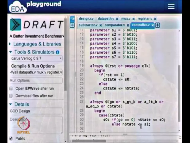
So, I am going to use this simple assumption that stateS naught is going to be 0 0 0,state S 1is going to be 0 0 1, so onup to S7. So, one thing I want to do is, I want to… So, I am now going to model that, to do that I am going tocall sub, I am going to use a keyword called parameter. So, the parameter is a key word,you can see that it turn purple.
So, parameter, I am going to declareeight parameters, the eight parameters will stand for the state encoding that I am going to use. So, parameters naught is 3 tick b 0 0 0. So, the tick, the apostrophe there, that you see is called a tick and tick isusually just to theleft of the keyboard.
You have to press a shift and the key that is just to the left of keyboard that is called a tick. So, this is also the closing apostrophe mark, if you want and will need eight such parameters, I am going to make copies of this. So, I have eight such parameters,now I am going to name them s naught, s 1 to s 7.
So, instead of referring, I have all the 8 statesand I want to assign the appropriate vectors tool. So, I have all the differentstates is assigned. So, now, the interesting thing is this c stateand n state, this c state and n state are supposed to be state register.
So, there are 8 states, soI actually read only 3 flip flopsfor it, soI made a mistake. So, I need 3 flip flopsforstate and next state, sothis states and next state can actually takeonly 3 bits. So, they will be from 0 0 0 to 1 1 1and so on, so it is enough to have it as a 3 bit value.
So, I have declared c state and next state as a 3 bit registers. Now,let us go and write each one of thesemodules, soagain let us go back and look at the picture. So, the picture says,I need a state register, I need an input forming logic and I need output forming logic.
So, we need these three, let us see how to design that. So, I will start with the state register, because it is the easiest to do. So, the state register is as simple as this, always at…If there is a reset or if there is positive edge of clock,then we want our state register to work, to take the new values.
So, we want our state machine itself to be asynchronous. So, if reset is one, which means from the external worldI cannot force the external world to synchronous the input with respect to clock. So, I should be able to take the input from the external world at any point of time, soif reset is 1, the picture says if reset is 1, I should be at state s naught.
So, what I am going to do is, I am going to say that next state must be equal to s 0. So, what this does is,it isensuring that thevalue that you get here, sowe have, solet me look at this. So, if reset is 1, then we have, we are going to have the next state to be s naught.
So, if we come back and look at this,so this is state and this is next state, sowe want the state to be s naught. So, this should be the current state, the current statemust be equal to s naught, in else we know that this is we came in because of not reset, the state machine is running. If the state machine is running, all I have to do is, this state should copy the next state in every cycle.
So, I am going to put that, current state should just be equal to next state. So, when the clock comes,whatever you call as the next state, actually becomes the current state. So, in some sense you set up the next state, sowhen you are in the current state, you set up the next state and the next state when the clock cycle rolls over, that becomes the current state.
So, that is what we have here and this is essentially the logic required for sequentthis state register. So, it is a fairly simple thing, soit has either the current state is s naught or the current state is n state, sothat is clear from the picture here. Either, the current state… So, I callthiscurrentstate not next state, soI will strike it and write it down,this is current state.
So, the current state is because of reset, current state can become s naught state or if there is no reset, every time the clock comes in, the next state value will reflect in the current state, so it is as simple as that. Now,let us look at the combinational logic. So, I am going totry and writethis, solet us see what to write first.
So, maybe we can write the next sate logic first and then, we will write the output logic, so let us look at the next state logic. So, for the next state logic, I need the state machine, solook at the state machine. So, every time based on the current set of inputsand so on, it is supposed to make transition.
So, this is the crucial part of designing the state machine. So, I will write the next state state machine, the next state part of the state machine. This is remember first of all, it is combinational logic.
So, it is notgoing to have reset or clock,I am going to put only the combinational inputs and again, if you look at the picturethe input forming logic or the next state logic is taking, go all these three differentinputs and this current state itself. So, these are the inputs to the next state logic. So,I am going to put that, sogo is one of the inputs or these are inputs which are actually coming from the data path.
So, we took care of inputs coming from the… So, this is coming from the external world, a greater than b, a less than b,a equal to b are coming from the data path and internally, we have the current state register itself. So, if any of these things change,then the next sate logic is supposed to react to that. So, again if you look at the picture,next state will change if any of these things changes.
So, because it is a combinational circuit, I have put all the conditions here, I have put all the inputs,that is what s a good combinational circuit is. All the inputs that are supposed to begiven to a combinational circuit should appear in the sensitivity list. I have put all of them in the sensitivity list,now I want to go and write, how this thing should look like.
So, the most common way in which the next state logic and the output logic iswrittenis using a case statement. So, I am going to make case on current state and the current state, if you go and look at it, the current state could be, so it is a 3 bit vector. So,it is a3 bit vector, which means it can take valuesfrom 0 0 0 to 1 1 1 and I have actually named0 0 0 to be s naught,0 0 1 to be s 1 and so on up to 1 1 1.
So, I can instead of assigningthem asvectors with the explicit bit values, I can start using thestate names. So, in some sense, this parameter what it is doing is, it is taking the bit vector assignment it is state assignment and from now on, we can call them by the name s naught s 1 s 2and so on,that is what we did here. So, the c state equal to s naught, it is technically c state equals 0 0 0.
But,since we havedeclare this is a parameter, we can call the bit vector 0 0 0 as s naught. So, this current state now the case statement, soc state can be, the current state can be from s naught to s 7. So, I am going to write oneswitch case for each oneof them, so let us start with s naught.
So, if it is s naught,let us go and look at the state machine. I I am at s naught,let us see the conditions forany transition. If it isG naught, you stay in s naught itself,if it is… So, if it is go,if it is not go,you stay in s naught itself otherwise, you go to s 1, sothese are theonly twoinput conditionsto which you react.
So, if goequals 0,then you are going to say the next state must be equal to s naught, else I am going to say that next state must be equal to s 1. So, it is fairly straight forward, if you think about it. All we are doing is, isgo… So, based on the state diagram that we have, the state diagram in this particular state looks at only one input.
Eventhough, there are several inputs coming in to the state machine, it looks at only one input namely go,all the other inputsdo not matter for this state. So, s naught if go equals 0,then we go to s 0 itself,that is looking back otherwise, the assumption is the external input is alreadystable and the external world has given is go equal to 1. When go equal to 1, we are ready to go to thestate called s 1.
So, now, we have several other cases, soI am going to write one such case for each one of these states. So, now, if you go and look at s 1 state, s 1 state we just blindly move to s 2 state. So, there are some outputsthat we are driving, but these outputsare not for now, we are going to put it in the output forming logic.
So, in terms ofjust the transition to the next state, if current state is s 1,you blindly move to the next state s 2. So, without any extra check,I am going to just say that next sate should be equal to s 2,nothing else. Similarly, if you are in s 2,let us look at this, if we are at s 2,we blindly go to s 3.
We only go to s 3 and we actually turn these signals off, but turning those signals off is part of the output logic, from s 2 we blindly move to s 3. So, I am going to put that in, instate equals to s 3, s3 is a slightly interesting state. So, if we look at s 3, then there is a greater than b,a less than b,a equal to b.
Now we are going to check the other3 inputs. If one of these conditionsis true, we will go to the appropriate states namely s 4, s 5 and s 7. So, s 3 isslightly interesting state, I am going to write that now.
Now, I have to check the conditions. If a is equal to b, so these are the three things, so let us look at the inputs. There is a greater than b, equal to b and less than b, soI can check them in any order, solet me start with a greater than b.
If a greater than b is equal to 1, then the next state is supposed to be s 4. Elseif,a equal to b is equal to 1, then next state equals s 7. Else if, actually this is the last case, Ican just leave it as else, next state equals s 6, s 5.
So, what we have is, we have taken care of these three things, either it goes to s 4 or it goes to s 5 or it goes to s 7, so my be to reflect thatI will write it inthat form. So, if it is less then b,it should go to s 5, the else class will be if it is equal, in which case I will go to s 7. So, what we have so far is, for s 3 you have taken care of the fact that,it is going to be amultiple transactions are possible based on the inputs.
Again let us comeback and look ats 4, s 5 and s 6, they do not have any conditions underwhich they are moving. S4 blindly moves to s 6, s 5 blindly moves to s 6, s 6 blindly moves to s 3. So, there are no checks that you need to make and in fact, s 7 also blindly moves to s naught.
So, we do not have to make any more checks, the only checks were at s 3, which is supposed to be the comparison state. If all the other states are only changing the outputs, there is nothing else that has to be check, soI am going to write all of them in one go. So, if we are in state s 4, this state diagram said go to s 6, if we are instate s 5, the state diagram says go to s 6 also.
If you are in s 6, the state diagram dictated thatyou shouldgo to s 3 and if we are in s 7,it supposed to go to s naught. So, you have taken care of all the different eight possiblecases that we can encounter. In general, it is alwaysa good practice to put, what is called a default statement, if we infer combinationallogic.
So, this isa general principle, soby default the reset state is what you want to be yet in general, soI am going to put that and this brings me to the end of this always block. So, this line number 27 to line number46 here, this takes care of,the line number 27 to line number 46 here takes care of the input forming logic or the next state logic. So, I am going to write something very similar for the output forming logic, sothe output forming logic in fact, it taking the same set of inputs.
So, it is going to have go, it is going to have all these inputs a greater than b, aless thanb,a equal to b and so on. It is also going to take the current state, in the output forming logic we will not write to the next state. We will not write to next state but we will be writing to all the other signals.
So, let us look at all the other signals that we are driving from the controller. From the controller, we are driving all these four lines and there is aoutput enable line and there is a done line, all of these are supposed to be driven from the controller. So, I am going to write a piece ofVerilog to do exactly that.
So, the first thing I am going to do is, I am going to take thesensitivity list as it is. So, this sensitive list is forthe combinational logic that is for the output forming logic, again here how are we doing, how are going to do things now. So, in this case there are multiple things that are possible, sowe could either be in… So, there are several things that can happen here, but default I am supposed to be in… So, so I can be in state s naught, s 1, s 2, s 3, all the way up to s 7.
So, what I am going to do is, I am going to assume thatfor each of these states, if I derive all of them to be zeros, solet us say I drive done equals zero,a select equal to zero, b select equal to zero, a load equals to zero and b load equals to zero. Let us say I drive these five things, there is alsosupposed to be an output enable, sowhich are forgotten here, there is also another line called output enable So, all these lines, I am supposed to be driving from the combinational logic. So, let me go back and look atit, maybe I have not declared output enable also here.
So, I will that is alsoa reg, soit was part of my module description,I added that now, soall of those are ready. So, I need to be driving these six values. So, the safest valueto drive for all of these six values is actually 0, because if a load is zero and b load is zero, you are not going to take anything from the externalworld.
So, we said in state s naught,we willnot do any work at all, we will wait for the go signal to come and only then, we start our work. So, that work of coping from the external worldis actually at state s 1. So, what we will do is, we will assume that by default.
We are going to assign values to each of all of these signals in all of the states. So, if you go and look at, how next state is assigned under every possible if then else condition and for all cases, we have an assignment for next state. So, that is how you infer a combinational circuit under all possible branches.
We havesomething for the sum assignment to the next state. Similarly, under all possible cases we are going to assign values to thesix signals. The six signals are going to be these six signals, a select, b select, a load, b load, done and output enable, for all of them I am going to assign values.
So, I am going tostart with case of current state and sothis one would require eight cases, so let us start with s naught. So, if I am in state s naught,I am supposed to be driving all these six values to zero, all the six. So, these six signals all of them have to be driven to zero, soI am going to do just that.
If I am in state s naught,then I know that a select has to be 0, b select has to be 0, then I know that a load has to be 0, b load is 0,done is 0 and output enable. So, this s naught is this reset state, sowhen it is reset state, there is nothing to do, sowe setup all the differentsignals to be 0. So, there is nothing to do here, it is not any special state and for all the otherplaces, for all the other states we are going to setup various signals one after the other, solet us put s 1.
So, since I am going to assign six values in each one of them, it is actually safer to doa cut and pasteand go and change the values to whatever is required. So, I am going to makeseven such copies and I will go and change them later. In fact,eight such copies one for the default class, solet us try and change one after the other.
So, let us start with s naught, so s naught is already ready. When it is in s 1 let us comeback and look at thestate machine. So, look at this state machine, when it is at s 1, a select, b select, a load and b load should be 1and done and outputenable are by default assume to be zero.
So, I am going to change only those values now, I changea select, b select, a load and b load, all of them to be1 and done and output enable are setup at0, so this isokay. Then, at s 2,at s 2 if you notice, so this a select, b select, a load, b loadare supposed to be brought back to zero and done and output enable or still zero, because we are not done at this state anyway. So,whatever conditions we have here now,seem to be just right, so s 2 whatever we have here seems to beokay.
Let us look at s 3, sos 3 again what we have is, when we are at s 3, we are not changing any of the… So, from the controllers point of view, sothe data path is going to give us value a greater than b and so on. From the controllers point of view,there is really nothing to do in s 3, s 3 will just take you to the correct set of states, sothat we can turn on either register a to copy or register b to copy and so on. So, again we will keep fors 3, all the outputs to be 0 itself, s 4 gets slightly interesting.
So, at s 4 we know that,in terms of the state machine,the a register must have aload, sothis a register must have a load and soI will change that to 1 and everything else is supposed to bea 0, sothis isfine. So, what we have now is, we have a case where we have modified the load, soagain if you want to go andlook at the picture, let us look at the actual picture for this. So, let us look at this case, so if we want this to be the loop back path, then the sub tractorsoutput which is t 1 is going to come to the multiplexer and to a and if we change,if you put a load equal to 1, then we are essentially doing a equals a minus b.
So, in order to do that, we only need this subtractor, sothisa load should be 1 and by default, this a is anyway set to… So, if a select is set to 0,it will take it from the subtractor. It is not supposed to be take it from the external world, sowhich is fine. So, that is the safest case and anyway we have that.
So, at s 4 I want a loadenable to 1, at s 5 I want b load enable to be 1. So, farthings are very straight forward, at state s 6, soagain if you go and look ats 6, there is nothing there, there is no change with respect to the outputs. We are not done yet, weare still calculating and soon, this is justa dummy state.
So, in the dummy state we give all the signals to be 0. So, again the comparatorand the subtractor all of that sequence withthe data part will work, so everything is fine, at s 7 it gets interesting. So, at s 7what we have is, we havewe arrive at s 7 only when a is equal to b.
So, at, when a is equal to b, what we are supposed to do is, you are supposed to turn on the output enable signal. So, that the output register can register values and we should alsoindicate to the external world that, done is equal to 1. So, I am going to put that now, I am going to tell the external world that the GCD machine is done computing GCD of these inputs and I am also going to make the output enable to be 1, sothat the output register can copy the value.
So, these two are done finally, in the default state which I always put just for safety purposes. So, in this case there is s naught to s 7, sothere are 8 states and I captured them using 3 bits. So, all the eight possible combinations are captured, but if I had only 6 states or soon, then it is possible that, yourstate machine can get intowrong state, when you start the power.
So, when you power of the circuit, it is possible thatitgets into one of these unknown states, so it is always safe to put at default class. So, in this default class, it takes care of various othersignals and with this the state machine is actually done. So, let us take a look at this, what I did was, I designed one always blockfor the state register, one always block for the next state logic and we have this bigalways block for theoutput logic.
So, the input logic is fairly straight forward, the output logic seems to have all these different bits, we need to be controlling them. So, we have all of them here all of them are done, so let me go and save it. And as before I am going to go to the design file and I am going torunit once,just to see, if there are any errors anywhere.
So, right now if I did not make any mistake in the controller, then I should not get any errors at all. So, let me see, they still seems to be controller reference one time, sothere is a problem there. So, to do that I have to go back and add the controller dot v as the… So, I add controller dot v, save it.
And hopefully there was no mistake in the state machine that I wrote, let us see the results. So, there are some errors, it says incomprehensible, case expression, there issome syntax error and it seems to be in line 52 down till line 100. So, let me see what it is.
So, line 52 of controller dot v, let me see what it is. So, line 51 is this, line 57 is this and soon, it looks like I actually did not putbegin and end, because there are multiple assignments herefor each one of them, I think I have forgottento input begin and end here. So, that is all I am supposed to do now, I will do that,let me finish that, let me put it everywhere that I need.
So, I am not going to worry about the formatting right now, let me just put it and I can come back and change the formatting later, sothat will become readable. So, I should have anticipated that, soI should have done better than thisby being careful about anything that goes inside in case statement. If there are multiple statements, I will need begin and ends in case, soI am going to put that.
So, now, let me save this and try and run it once more. I go to design file and I run it once more, if there are no further mistakes, now I should have no errors at all, let me see. So, there is one more error, unable to bind wire reg memory s 3 in GCD machine.
So, let me go and look at GCD machine line number, socontroller line number 42. Let me see whatline number 42 is, So I think I putcapital S3instead ofsmall case, soI fixed it now. So, things like this you shouldget used to.
So, that is why you have to read every single error and not just say that, there is something that is wrong. If you go and read,usually you will understand what the errors are about. In this case, it said some s 3 is not found and when I came back and looked at it, it looked like I put a capital letter there, wonderful.
So, now, there is no error at all, this no error means I have the complete design ready now. So, if you go back and think about it, I started with the design and in the design, I said I will plug in the controller and data path. I did not worry about, how to design the controller and data path, later I said, I will go and look at data path,so the data path again I said I will pick all these things, I know that I need to subtract it,2 multiplexer,3 register and what not, I put all of that without worrying about, how to implement them.
Then, I implemented one after the other and in doing so, I always check whetherthere are any mistakes or anything like that. Finally, the controller is something that I design last and for the controller I gave you some design principles that, if the state machine always has three different pieces, one called the state register, one called thenext state logic and another called the output forming logic, for each one of them I have given the way to describe them. So, in this specific case the state machines seems to bea Mealy machine, because the outputs changedbased on theinputs as well as the current state.
So, if it is just the current state, then you would have only c state in the sensitivity list. If it is a moore machine, you will have only the current state in the sensitivity list, because we know that the outputs can be driven only based on the current state. So, once we have that, we are ready to now actually go and writea test bench for this.
So, we are done with designing the whole circuit, now we are ready to go and writea test bench for this, which we will do in the next module. So, I suggest that you go back and look at the Verilog files that I have suppliedalong with this and you keep this side by side, when we go andwatch the videos. So, that we will understandwhat the different details are and if you have anydoubts in any of these things, go back and look at the Verilog file.
I am sure that the Verilog file has captured everything that you need. You go back and look at it slowly and come and revisit the video, I am sure you will understand this. So, it is not rocket science, it is not very hard to understand, it is just that you haveto pay a little attention to all the little details that is there.
The key thing that I want you to take away from this specific module is that, designinga state machine is fairly straight forward. Once you havea state diagram with you, you go and assign some parameters, sothat the state assignment is taken care of and you can use those parameter namesas the state names. You design three always blocks, one for the next state logic, one for the output logic and one for the register itself.
And this register should always have a reset, it should not be a… So no state machines should be designed without a reset, it should always have a reset. In general, we also make them as asynchronous reset, but even if you make it a synchronous reset, it is okay. As long as you have a reset, that is good for the state machine design.
So, we will talk about some of these fundamental principles about, what is good and what is not good for a state machine in the next week’s lectures. But, so far what we have is, in this week we have only been looked at Verilog and we seem to have come to the end of designing the chip itself or the GCD. The only thing that we need to put in is the test bench and check whether the whole thing works.
So this we will do in the next module. So, thank you and I am hoping you see back in the next module, see you soon.




![Excel to Power BI [Full Course] 📊](https://img.youtube.com/vi/gjnnqsdvAc0/maxresdefault.jpg)





![Visual Calculations in Power BI - DAX Made Easy! [Full Course]](https://img.youtube.com/vi/JITM2iW2uLQ/maxresdefault.jpg)




![Beginner to T-SQL [Full Course]](https://img.youtube.com/vi/cACat4KNncg/maxresdefault.jpg)