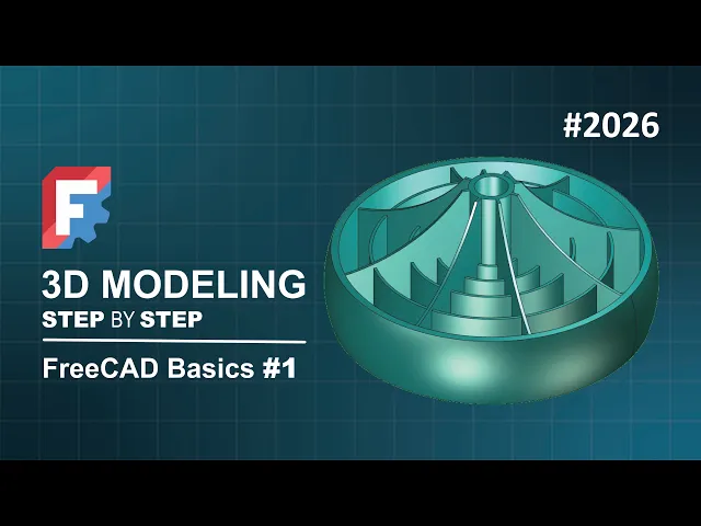
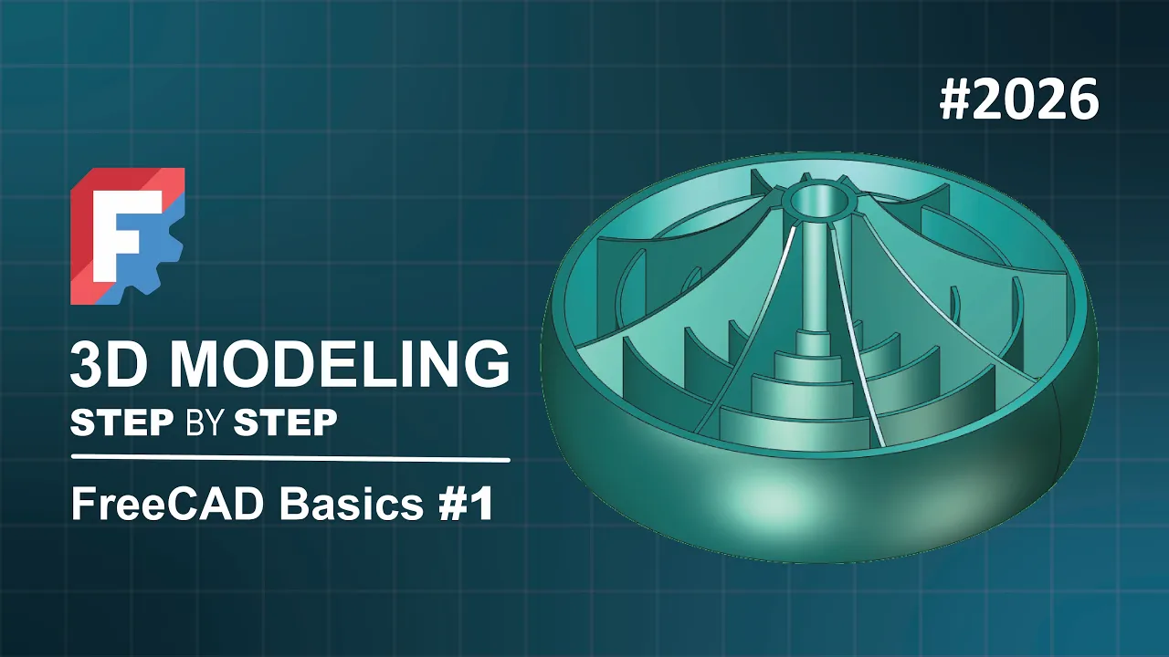
In today's video, we will apply some basic 3D modeling concepts in FreeCAD using the main 3D modeling workbench to create this model. If you are new to 3D modeling using FreeCAD, keep in mind that FreeCAD has its own way of working. It is different from other 3D modeling programs.
FreeCAD works based on workbenches. That is why in the toolbar area, you have Part Design workbench as the active workbench in the workbench selector. This is the main 3D modeling workbench in FreeCAD.
It allows you to model everything from basic solids to solids with more complex geometries, but with some limitations. To start modeling the 3D model, we need a document. To create one, simply click empty file in the new file area, or if you prefer a faster way, press control plus N.
To save the document, press control plus S or click the save command icon in the file toolbar and set a name. After creating and saving a document, it is time to start modeling. But before we begin, we need to understand the geometry of the model and identify a starting point.
This is important so we can plan the sequence of operations needed to reach the final shape of the 3D model in FreeCAD. Right away, we can see that the model is made of simple geometries and some slightly more detailed ones. This suggests using extrusion, pattern, revolution, and hole operations.
In the Part Design of FreeCAD, this means using pad, polar pattern, revolve, and polar pattern and hole to create the solids. But these commands alone are not enough to give us the final shape of this 3D model. We need to use another workbench that allows us to create 2D geometries, and from these geometries we will create the solids in the Part Design workbench.
Okay, let's put this into practice now. Create a body object by clicking the new body icon in the Part Design Helper Features toolbar. If you're unsure what this object does, know that it is just a container.
It holds the logical sequence of how you are building your 2D model, but it's powerful enough to let you change your model's parameters. Without this object, it is impossible to model in the Part Design workbench, so we have to create it. Let's start by creating the extrusion.
The extrusion will be a combination of a sketch from Sketcher workbench and a pad feature from Part Design workbench. To create a sketch, we need to pay attention to this group and these axes. Based it on the drawing page, we can attach the sketch in the front plane.
The idea is to create a geometry for this shape in the sketch. So, in the Part Design workbench of FreeCAD, go to the Part Design Helper Features and click on the new sketch command icon and select the XY plane as the attachment plane for this first sketch. As you can see, we're in the Sketcher workbench and the idea here is to use the Sketcher geometries, these tools, to create a geometry and the Sketcher constraints to constrain the geometry and set its dimensions.
Let's start by selecting the polyline tool. Just click on the polyline command icon and create a base horizontal line, next vertical line, horizontal, and vertical. To skip the tool, right click two times, go to the Sketcher geometries, expand the arc tools, and select the arc from three points, and then create a base arc.
And skip the tool, right click. As you can see, here we have a geometry, but this geometry is not a closed geometry. We need to close this geometry because if we leave the sketch in this way, the extrusion or the pad feature of part design or bench will not work.
Select these two end points in this way and go to the sketch constraints and select this one here, constant constraint. And as you can see you have this. Select these two end points and place constant constraint.
Now we have closer geometry. Select this end point and the origin point and constant constraint, okay? Five degrees of freedom.
Now we can set the dimensions of the geometry without problems. Start by selecting the dimension tool, click on the vertical line and click off. And what to do here?
Just add 40 mm, which is the length of this line here and then press okay. And next, select this vertical line, create a vertical distance of 19 mm. And next, select the horizontal line, this one here, 8 mm and this one here, its length will be 40 mm.
This arc here, this arc here, the radius will be 50 mm. And as you can see, the sketch is full constrained. Now we can close the sketch without problems.
And now, in the part design, let's press home on the keyboard to center the sketch on the 3D view. Now that we have the first sketch, we can create a solid using the sketch. Go to the model tab on the tree view, select the first sketch, this one here, and go to the part design add the features, these tools here, and click on this icon to extrude the sketch.
On the 3D view, we have a preview of the final result. This this solid has a length of 10 mm and the extrusion mode is one-sided as you can see here. The first thing we have to change is the extrusion mode.
Here we need a symmetric extrusion as we can see on the drawing page. We have a we have a symmetric extrusion. So, go to the extrusion mode and change it to symmetric.
And then the dimension tab, don't change it. Just change the length to 0. 8 mm.
This is the length of this extrusion. And if you want to see the final result, you can go to the preview and check the show final result and then uncheck this option. And this is the final shape.
Now, just press okay to finish the pad parameters. This is the first shape of the 3D model. The next step is to create a polar array of this shape around the Z axis.
To do that, it's very very easy. Just go to the model tab, select the pad feature on the tree view, and go to the polar pattern command icon. Click on it.
Press home on the keyboard and as you can see here we have a preview of the final result. And this is not correct. We have to fix it.
Go to the polar pattern parameters and the first thing to fix is the axis of this polar pattern. Change here to Z axis and it's now correct and fix the number of occurrences to eight and press okay and we have this as you can see. The next step is to create another sketch attached it to the front plane and that sketch will create geometries that we'll use to create the next shape.
Go to the new sketch command icon, click on it, and select the XY plane as attachment plane for this sketch. Click on this icon, switch to a view, and now we can see the axis crossing. Okay, the workflow here is the same.
We use the sketcher geometry to create the geometry of the sketch, and the sketcher constraints to constrain the geometries. So, let's start by selecting the rectangle tool and create a base rectangle starting from the horizontal axis. Skip the tool, select this line and delete it.
Go to the sketcher geometry, select the arc from three points, and create a base arc in this way. Skip the tool, select these two end points, make them constant, select these two points, and make them constant. And now, we need to make this line and this one here equal.
To do that, it's very easy. We need to select these line and this one here, and place equal constraint for degrees of freedom. Next, select the dimension tool.
Let's start by setting the length of this line here to 2 mm. And the height of this line here to 20 mm. And next, the radius of this arc here to 30 mm.
And now, the distance from this vertical line to the vertical axis 40 mm. And the geometry is fully constrained. If you want, you can hide these all constraints.
To do that, press this icon. And now, let's select rectangle tool again, and let's start creating these rectangles. We need four rectangles here.
The next step is to make the height of these all rectangles equal to the height of this line here. To do that, it's very easy. We can start the selection from this vertical line, and then do this, and then place equal constraint, and we have this.
Now, we need the same width for these all rectangles. To do that, we can select this line, this one, this one, and this one here, and then make them equal, and then select the dimension tool, click on this line for example, click off, and set the length, which is 0. 8 mm, and okay.
We can select this endpoint for this rectangle, and then click off to create the horizontal distance, and the distance must be 32 mm, and I'll select this endpoint of this rectangle, click off, and set the distance to 22 mm. This point on the vertical axis 14. 8 mm.
From this point, sorry, from this point to the vertical axis 8 mm. Full constrained. Click two times to hide these all constraints, and I'll select rectangle tool again, and create a base rectangle, select dimension, select dimension tool, click on the vertical line, and the height of this geometry will be 43 mm, and the width 6 mm, and now we have to set the distance from the horizontal axis to this point here.
As you can see, we have one degree of freedom. Select this Select this horizontal line and out there horizontal axis, and set 3 mm, and now we have the sketch full constrained. Let's close it.
And next, with the sketch 001 selected, click on the revolve command icon, and I'll press okay, and we have this, as you can see. What is missing now is to create the a hole on this cylinder here, like we see on the drawing page. To create a hole is very easy.
We can zoom in and select this edge for example, and click on the hole tool icon. And here we have this. Now if we change to the front view, we can see that we have to increase the depth of this hole here.
We can do that by going to the whole parameters in depth and change it to 100 mm for example. Click off and as you can see, this is the result. Now we have to increase the diameter of this hole to 9 mm, which is the correct diameter, and then press okay.
And here we have the final result. This is the final shape of the 3D exercise. Thank you for watching this video.
If you find this video useful, please don't forget to hit like and share this video with your friends. Thank you for watching. I hope to see you in the next video.