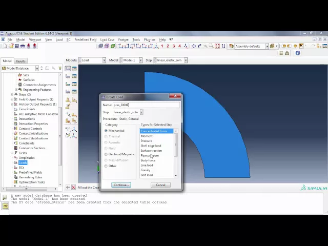
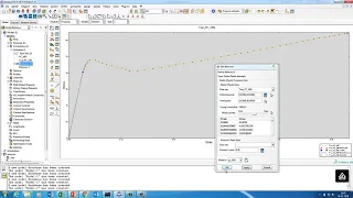
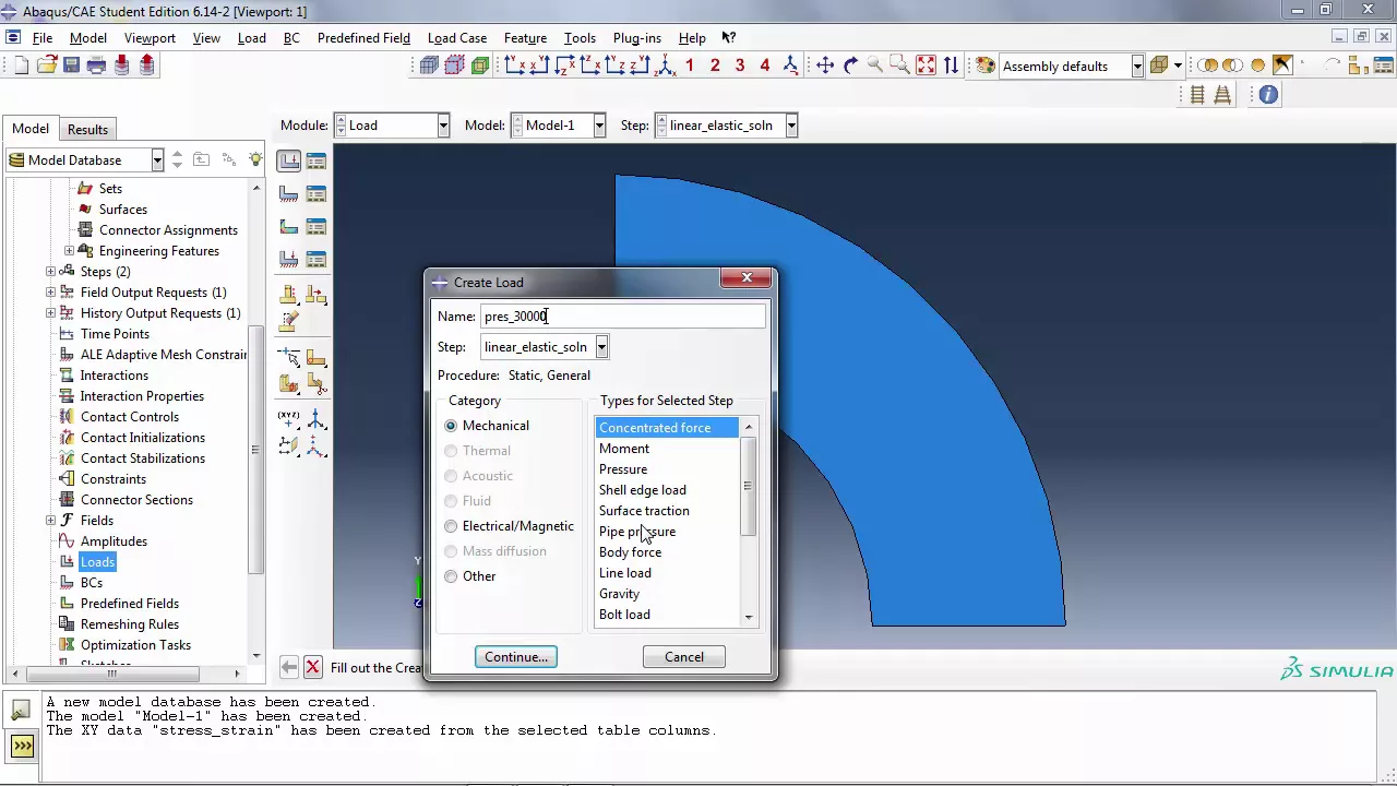
all right so let's go ahead create a part uh 2D deformable shell uh approximate size 200 no we're working in the smaller units so let's give a value of uh 10 we're going to go ahead and draw a couple of circles with the dimensions of let's make that 1 uh 75 for the radius and then the other one draw another circle from that same center with a radius of one and then I'm going to do my usual thing meaning drawing a line going from the center horizontally to intersect uh the Outer Circle and then draw another line from the center vertically to intersect the Outer Circle and then we're going to delete a whole bunch of things by using this icon which is Auto Trim icon trimming all of these things except the um quarter circle like that that's what you should end up with it's all the units are in inches so it's steel modulus is going to be 29911 3 zos as poisons ratio is equal to3 is what I used for Simplicity we'll go to plasticity we are going to Simply pick the first one which is the plastic information you'll notice what happens on the information that you're asked to provide the first information must correspond to um the value that you have so here I have the yield stress is equal to 59 822 and can you tell me what should the plastic strain be for the First Data it has to be zero because that is the yield strength of the material that I'm inputting as the first input value then I'm going to continue that enter and the next point is going to be 64450 tab gives me the next plastic strain which is0 8 41 next one would be 68500 and the plastic strain is going to be 029 269 make it and next one is 72,000 and the plastic strain is 0753 finally 75,000 0. 173 so these are some um stress strain data that I've tabulated of course when you have a stress strain data you don't want to give a thousand data points in here you want to break it into critical locations and give it a few data points like what you have here okay in case you want to take a look at this thing um let me go to plastic and just highlight these things and I'm going to right click on it and say create XY data do you see that in the bottom okay so it's going to read uh X values from column two that makes sense I want strain to be in the um x- axis so I'm going to call that a stress strain and say okay again right click highlight all your data point right click and then do create XY data so you've created an XY data and you should be able to plot that data if you want um as a matter of fact if you go under visualization uh there is this XY data that we haven't talked about that's create XY data there's also XY data manager that's the one you want right now because you've already created one XY data and all you need to do is simply say what plot and a miracle occurs this is the stress strain data that you're providing to the program in this case I knew he would ask the question go ahead so are we gonna make these come up with that plastic of ourselves is something to us yes okay so we're going to dismiss and of course that's going to remain until you switch the module to your part or Properties or wherever you are sections remember what I said we're going to do what kind of a problem are we solving it's a plain strain problem this is section of a tube long one we're going to give it plain St strain thickness of one and then we'll say Okay assign the section pick the whole thing I'm going to undo create set and say done plain strain and then create an instance of the assembly just like you've done before nothing unusual here okay have you kept up with me those of you who are working on your computer now comes the fun part steps so here I want to do what do I want to do linear elastic first yes so I want to do static General so I'm going to call that linear elastic solution don't touch this thing we will touch that later and um load what do I want to do for the linear elastic load okay it's a pressure load that I'm applying here and interior say done magnitude is 30,000 say okay now this is a quarter of a tube that I've cut what boundary condition do I need to apply symmetry boundary conditions on two planes so this is going to be um X symmetry I don't use this first item I use displacement rotation instead I'm going to go ahead and pick the um lower segment horizontal line and say done what do I need to restrain U2 and next boundary condition would be y symmetry pick the vertical line on the left hand side and restrain U1 okay okay we're going to switch to the mesh assembly what element do I want plain strain right is that correct notice it defaults to plain stress we're going to go with plain strain I don't want reduce integration question for you what else do I need to do if anything do I want incompatible mode or do I not care about incompatible mode or does it make a difference I'm just going to keep the regular default formulation um and I'm going to keep in mind that eventually I'm going to do plasticity analysis so I want to have a reasonably fine mesh all right I am not going to do convergence study I'm going to let you do that on your own however I do want to create a the structural mesh assign mesh control don't say quad dominated quad uh structured okay let's see what happens if I say the default of 0. 25 2 course 0.
1 better um meshed apart and I have have 176 elements I'm going to to refine that further by noting from my own intuition that as I'm applying the load where is it going to possibly do plastic deformation first Inside Outside Inside okay so I'm going to do a couple of edge seating in this case I'm going to pick these two edges did I pick that up and I'm going to do seeding by number it picks the default value that you had I'm it's equal to eight I'm going to make it equal to 15 and bias that single biasing uh ratio of two by the way in case you're wondering what the double biasing is it starts small from both ends and kind of goes large toward the Center or start small in the center flares out larger toward the two end and we'll say apply and see what happens um seems reasonable to me does it no one of them is reverse um so select uh flipping should I flip this one is that better I'm going to M the part and see what it looks like now does that sound good to you all right so I'm anticipating in this case ahead of time uh this is going to be linear static solution obviously um so we've created the mesh we're going to create a job um okay save my and submit this linear static job notice I've actually applied the correct load so from the results of the one Misa stress I should be able to make a determination whether the yielding will take place or not as as he suggested we're going to look at the results and um deform shape superimpose the undef shape as you were expecting this is going to be the outcome and what do I have for my van Misa stress maximum 63,360 perfectly uniform can you tell me whether this mesh is reasonable or not it better be okay so do you remember the Str strain data that I had provided is it going to yield yes okay so it is going to yield everybody agrees on that one okay so you've done your linear static analysis everything is okay I'm going to go ahead and collapse that model copy that model to um now plastic model and open up the plastic model I've defined everything so far as materials except that in the steps I'm going to Simply um you have one of two options place it I'm still going to stay with static General continue uh um this flag you don't touch that for the time being can you tell me what that stands for nonlinear geometry flag that's nlg G oom for now we're going to stay as it is and go to the incrementation tab you notice what happens maximum number of increments is is equal to 100 can you tell me what that means it's going to take the load maximum load divide it into 100 increments of load increment size notice what the initial value for default is one what does that mean the first increment is going to be the maximum load you don't want that right so you have to give something a little bit smaller maybe . 25 that means I'm going to guess as the initial increment quarter of the load minimum you notice what it is 1 * 10 Theus 5 don't touch that one ever maximum one is okay now what happens in the program it takes your initial increment goes through the number of iterations of the Newton Herson approach what is it we have no control over it Abacus decides that automatically solves the problem can it converge to the solution in that first increment of load based on the number of iterations if it exhaust the number of iteration cannot approach it do you think what's going to happen next no my initial increment that I said is 0. 25 notice there's the minimum associated with that too since my initial increment did not converge to a solution it automatically divides that by two so my next load increment then is going to be instead of 0.
25 is going to be . 125 if it still doesn't converge after the required number of iterations it's going to divide that by two it's going to repeat this process until it hits the minimum value if it hits the minimum value and still cannot converge it'll kick out the solution and say you got problems very rarely that would occur okay that's the sequence of steps the thing that you don't have any control over is the number of iterations of the Newton arson approach that is done internally automatically by the software some other programs such as nastran allow you to control that as well let's say it reaches the solution with two or three increments say oh maybe my initial increment size was too small so the next increment multiplies that increment by two starts with an increment of 0 five after two or three iterations it reached the solution say oh I can even incre increase that more you know what I'm saying but the maximum is one sometimes you may want to be careful with that maximum of one reduce that to 0.