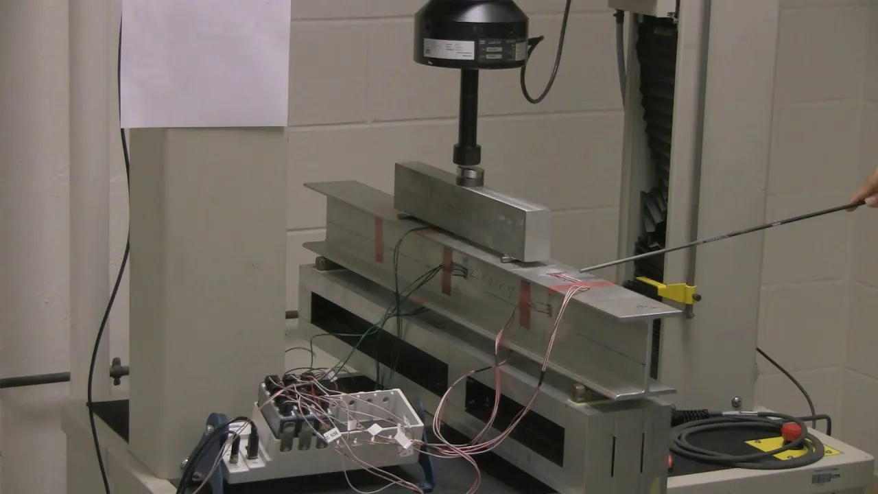
Hello everyone, we are going to be performing a four point beam bending experiment today. So firstly I go over the objectives of the experiment then to the set up and then we perform the experiment. The objective of four point beam bending experiment is to verify the Bernoulli's hypothesis.
The way you are going to be doing that is by comparing the experimentally measured strains with the theoretical calculations. Now coming to the setup of the experiment. So we have a universal testing machine.
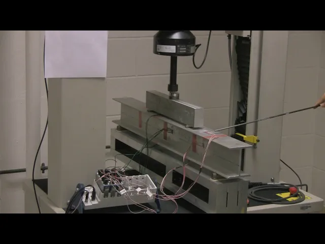
So, as you are aware, this is the crosshead of the testing machine. These are the two columns. This is a load cell.
So a load cell is used to measure the amount of load that is being applied. Connected to this load cell we have a bar that is used to transmit the load. The load is going to be transmitted through this ball bearing.
So if we take a closer look we have a ball bearing that is connected as such. And it is placed at the center. So the reason we are using this ball bearing is to make sure that only a force is transmitted and no additional moments are being transmitted.
The load is then transmitted to this crossbar, which has got 2 roller supports at the bottom. So the crossbar is placed in such a way that when a load is applied it gets equally distributed into two parts at the two locations. So if a load P is being applied, it gets distributed as P/2 and P/2 at the two locations.
So this is the I-beam that we are going to be testing. It is made up of an aluminium alloy. The I-beam rests on 2 roller supports, one here and the other one here.
So in total there are four roller supports, two below the below the crossbar and two below the I-beam. So in total there are four points of contact, which is why it is called as a four point bending experiment. So for this I-beam we have two sections of interest.
One is the side section and the other one is the center section. So the reason why we are considering two sections is because one of them is under pure bending and the other one is under simple bending or bending with shear. So from the shear force and bending moment diagram, you will know that the center section is under pure bending and the side section is under simple bending or bending with shear.
So at these two locations we have installed some strain gauge rosettes. Each strain gauge rosette has got three strain gauges and the angle between them is fixed. For the strain gauge rosettes that we are using, the angle between the strain gauges is 45 degrees.
So as you can see here for the side section we have three strain installed three strain gauge rosettes. It's one of the top, one in the middle and one at the bottom. In the same way for the center section, again we have three strain gauge rosettes.
It's one of the top, one in the middle and one at the bottom. So for each section we have in total 9 strain gauges on the side and 9 string gauges in the center section. We will firstly will be performing the experiment for the side section and then we'll repeat the experiment for the center section.
So right now I've connected all the side section strain gauges to a data acquisition system. So this is a data acquisition system by National Instruments. It has got three modules.
Each module has got four channels, so in total there are 12 channels. So as we don't have enough channels we will be performing the experiment in two parts. First for the side section and then for the center section.
So this data acquisition system is connected to a LabVIEW software. LabVIEW software is used to measure the strains that are being applied. The MTS TestWorks software will be used to control the universal testing machine.
So now we take a break and take a closer look at the strain gauge orientations.

![Upbeat Lofi - Power and Energize Your Workday - [R&B, Neo Soul, Lofi Hiphop]](https://img.youtube.com/vi/ONcY0BM5EAg/maxresdefault.jpg)

















![Live Aid (Queen) Full Concert [1985, London, Wembley Stadium]](https://img.youtube.com/vi/PLIAp5nr0q0/maxresdefault.jpg)