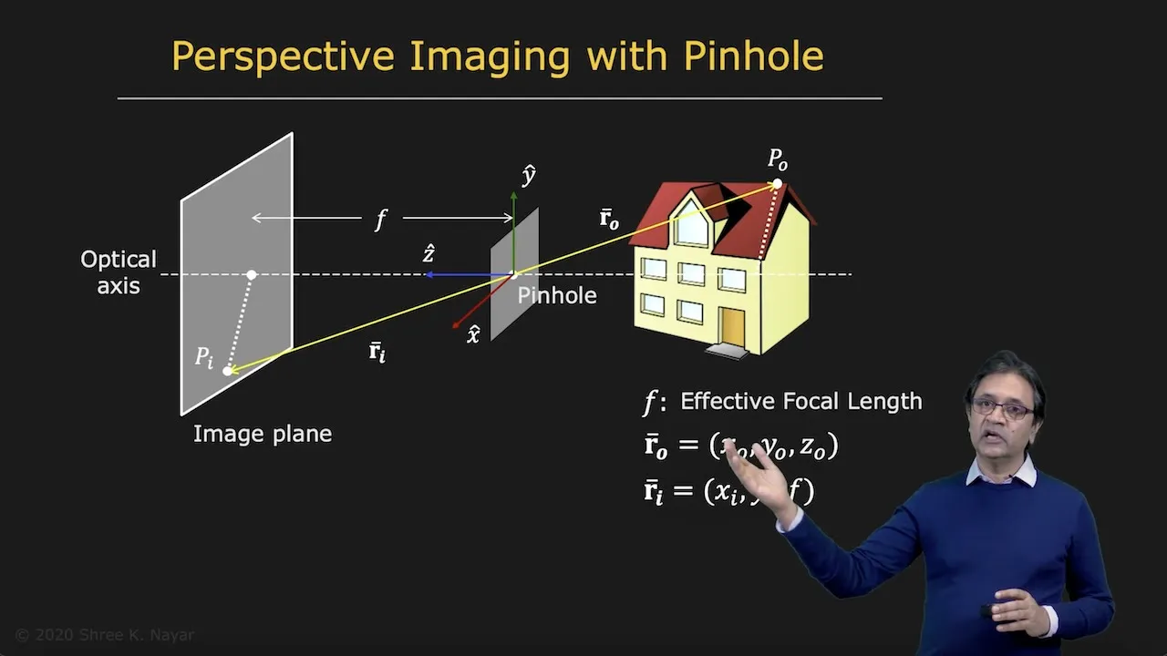
so here you see a three-dimensional scene on the right which is a house and you're seen a screen or let's call it an image plane on the left and the question that I'd like to pose to you is is an image of the house being formed on the screen well if you consider any point on the screen it does receive light from a lot of points on the house but you don't see a clear image so could argue that there is an image being formed but it's a muddled image and not a clear one so
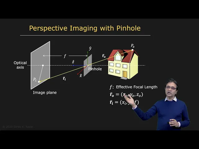
then the question is how does one create a clear crisp image of the house on the screen well the simplest way to do this is by using a pinhole a pin hole is an opaque sheet with a tiny hole in it and it's placed between the scene and the image plane as shown here and now if you take a look at a single point on on the house you see that there is a single Ray that travels from that point in this case p 0 to the image plane and projects onto the point Pi so
every point the scene now projects onto a single point in the image so we want to understand the relationship between p 0 and Pi so for that first we're going to erect a coordinate frame XYZ threedimensional coordinate frame placed at the PIN hole with the z-axis pointing along the optical axis the optical axis by the way is the axis that is perpendicular to the image plane shown here as a dotted line so the z-axis point towards the image plane and lies on the optical axis and the distance between the pin hole and the image plane
is called the effective focal length and that's F so now we can write the point p 0 using the vector r0 and that has coordinates x0 y0 z0 and its image can be denoted as RI which has coordinates x i on the image plane Yi and the Z coordinates is going to be F so irrespective of where the point lies in three-dimensional scene irrespective of its Z component the Z component on the image plane is always going to be F the effective focal length so now if you consider these two triangles right here this one
that I'm showing here and this triangle that's here on the back behind the pin hole these are similar triangles and from these similar triangles you can write r i the vector RI ided f is equal to the vector r0 / by z0 z0 is by the way the Z component of the three-dimensional point the point in 3D in other words it's the depth of the point in 3D and since r i and r0 are vectors we can break it down into its components and say x i by f is equal x0 by z0 and Y
I by F isal y0 by z0 these are the equations of perspective projection very simple equations but create some fairly non-intuitive effects in images so this idea of pinhole projection and a pin whole camera actually dates back to 500 BC there were Chinese philosophers who were writing about this concept way back then and then somewhere around 1,000 ad the Arab physicist alhazan he wrote a book called kitab Al manazir it's actually one of the first Optics books he describes in great deal this concept of the pinhole camera and it's only in the 16 Century that
this concept actually came to the West it became very popular among artists particularly as a as a tool for rendering accurate depictions of three-dimensional scenes so here is a sketch by Gemma frus it's a Dutch mathematici where you can see that there is a wall with a little pinhole a little hole in the wall and behind this wall is a second wall and so the three-dimensional scene gets projected by this pinhole onto a two-dimensional image and now you can imagine that a an artist can walk up to this wall and sketch out a very accurate
geometrical representation of the perspective projection of the scene a picture by the way this is this concept was called camera obscura which in Latin means a dark chamber well when it comes to the pinhole camera as with many other things in life nature got there first so here is an eye which is a pinhole eye in the case of this a creature this is a shelled sea creature called Nautilus pompilus you can see that it has an eye right here and it has a fairly large pinhole which creates an image and there is no lens
in this eye all right now let's take a look at some of the properties of perspective projection the first one I want talk about is what is the perspective projection of a line in 3D so here you see a line in 3D and you have your pinhole right here and we know that the line and the pinhole that is a line and a point uh Define a plane in 3D and all the Rays of light that pass through the pinhole lie on this plane and for that matter all the Rays of light that pass through
the pinhole towards the image plane almost also should lie on this plane and so the image of this 3D line on your 2D image must be the intersection must lie at the intersection of this plane and the image plane so right here so in other words the image of a line in 3D has to be a line in 2D and this is why you find that in photographs straight lines in the scene will map to straight lines in the photograph so next we want to talk about image magnification you have an object of a certain
size at a certain distance what is going to be its size in the image so for this we're going to use a little segment here a0 B 0 of length d0 a0 is x0 y0 z0 and B 0 is the same same coordinates displaced by X Delta x0 and Delta y0 so this segment lies on a plane in the scene that is parallel to the image plane and of course it produces an image which is another segment and that segment is AI bi we want to understand the length of what the length of the segment
aibi is going to be due to a segment of length d0 in the scene so the ratio of the length of the segment in the image to the length of the segment in the scene is called the magnification and this of course can be written in terms of the displacements Delta x0 Delta y0 Delta XI Delta I Yi as follows so now we want to substitute for the displacements in the image so we can simplify this and to do that what we're going to do is apply perspective projection to the point a0 and B 0
in doing so we going to get four equations one for x one for y for each one of the two points A and B and using these four Expressions you end up with a very simple expression for the relationship between displacements in the image to the displacements in the scene and using plugging these back into the equation for magnification it turns out you get a very simple expr EX for magnification the magnitude of M the absolute value of M is going to be the absolute value of f that's the effective focal length divided by z0
which is the depth of the object in the scene so note that this z0 in the denominator this is a really interesting thing the size of the magnification of an object in an image is going to be inversely proportional to its distance from the camera and by the way the the sign of M is going to correspond to whether the image is upright or inverted in the case of a pinhole camera of the type that we've just talked about it's going to be inverted and therefore negative now let's take a look at some of the
manifestations of image magnification so here you see train tracks two parallel tracks the tracks must be parallel otherwise the train is going to have a problem right we know that these two lines are parallel in 3D and yet in the image they appear to be intersecting or meeting at Infinity as you go further and further away in terms of depth the two lines get closer and closer and this is because magnification is inversely proportional to distance Z z0 depth so you can actually have some fun with this effect magnification effect as a photographer here you
know that these two people are probably roughly the same height and yet the man seems to be standing small enough to be standing on the palm of the [Music] woman a couple of notes about magnification the first thing is that the magnification of an object can be assumed to be constant if the object is small compared to its distance from the camera so if this is the object it's range of depth values is small compared to its distance from the camera let's assume that my eye is the camera then you can assume that the entire
object is being subjected to the same magnification this is an interesting thing because there is a reason why in selfie say for instance your nose tends to look much larger than the rest of your face and the reason is that the nose your in a in a the case of a selfie the camera is actually quite close to your face and the nose is closer to the camera than your ears or your eyes and therefore appears tends to be magnified a lot more than the rest of your face and then you can also now talk
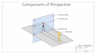
about once you have magnification you can talk about the ratio of the area of an object in the image to its area in the scene and that would be M2 now let's talk about an interesting manifestation of perspective projection and that's the vanishing point so in this picture this is a picture of a tunnel let's assume for a minute that the tunnel is a straight tunnel and the tunnel has a lot of lines these are lines in 3D for instance uh the White Lane lines right here and the edge of the yellow bands the two
edges of the yellow bands are also straight lines in fact the uh track of lights that you see up also lie up here lie on a line as well as these dark lines right here we can assume that all of these lines are parallel in 3D because it's a tunnel and yet all of them seem to be emerging from a single point in the image and that point is called the vanishing point so if you have a set of parallel lines in 3D they end up producing in it doesn't matter how many parallel lines they
end up sharing a single vanishing point they seem to be converging at the single point in the image and the location uh of this vanishing point in the image depends on the orientation of these parallel lines in 3D so how do we figure out given a set of parallel lines in 3D where the vanishing point is going to end up for that set of Point lines so here is a very simple way one can figure this out a very intuitive way to do it so assume that you have these two parallel lines and we want
to find the vanishing point corresponding to these two lines can you think for a minute how you might do this well remember all parallel lines in 3D share the same vanishing point so what you need to do is to construct a line that is parallel to these two lines that passes through the pinhole and wherever that line pierces the image is the vanishing point corresponding to the set of parallel lines in 3D so how do we find this well that's very straightforward given that we know perspective projection we first Define the direction of the set
of parallel lines in 3D that's given by the vector LX l y LZ and then we create a point which is in that Direction the point p in that direction from the pinhole of the camera so that's the point P that you see right there and now you simply perspectively project that point into the image using perspective projection equations that we already know and you get the location of the vanishing point so the vanishing point is a concept that artists have used extensively here is an example uh yanus painted the music lesson very uh famous
painting by this Dutch artist and in this scene here you have a lot of parallel lines or sets of parallel lines but let's take a look at this set right here you see that this set of parallel lines ends up converging at this point this is the vanishing point right here and what beir has done is plays what he considers to be the most important object or activity exactly at that place in this particular case it sits at the elbow or close to the Elbow of the student who's playing the piano he wants to draw
your attention to that activity so a lot of artists figured out early on that humans in any three-dimensional scene in any photograph tend to be drawn to vanishing point especially dominant V Vanishing points that are created by large numbers of parallel lines and so they tended they played the trick of placing the most important subject or activity at those points here's another interesting concept which is called false perspective this is Galleria spada by Francesco borini it's a beautiful little Gallery in Rome I've had the The Good Fortune of visiting it and it's a really compelling
effect so what you see here is a Archway or a little bit of a hallway and at the end of the hallway you have the sculpture and when you stand in front of the hallway you get the impression that the sculpture is roughly 150 ft away from you it turns out that the sculpture is only 30 ft away from you and the reason you have this very compelling effect or Illusion is because the pillars of the archway are actually getting smaller with distance away from The Observer so it's a tapered Arch way and this creates
this effect of false perspective which forces you to believe leads you to believe that the object at the end of the hallway is much further away than it actually is okay so we talked about the pinhole and how it can be used to create images but one thing we sort of set aside is the size of the pinhole what should the size of the pinhole be well we said it's a it's a point it's a tin little hole and that makes a lot of sense because the tinier the hole obviously you're going to have a
thinner better defined Ray going through but not quite if you look here you have the size of the pinhole used to take a set of images uh and we start with the largest size 2 mm here and because it's fairly large you're going to get a lot of blurring in the image because from each point in the scene as you can imagine you don't get as single point in the image but you rather end up getting a bundle of rays going through which creates a distribution of light in a in a circle circular region so
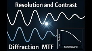
you get a blurry image as you start making the pin hole smaller 1 mm you see that it gets sharper 6 and then finally at 35 you get a very sharp image but here's the interesting thing you go smaller you make the pin hole even smaller actually the image starts getting blurrier again so here you see at 0.15 it gets a little bit blurry 07 it's even blurrier so why does this happen this is because of an effect in wave Optics called defraction so it turns out that if you have any opening and you have
a light wave that's passing through this opening there's going to be a bending of this these light waves at the edge or the periphery of the opening and the smaller the opening gets there's going to be more the effect of the bending than the light actually passing through and so you get severe bending as you get too small so then the question is what is the ideal size of the pinhole well you can calculate this and it turns out to be the diameter of the pin hole should be 2 * roughly 2 * square root
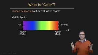
of the product of the effective focal length and the wavelength of light so in our case if you're interested in visible light images the wavelength lies somewhere between 400 nanometers and 700 nanometers so let's just pick the average 550 nanom you would plug that in there you would plug in the effective focal length and then you would get the ideal or close to Ideal pinhole diameter and that's what you should be using uh to capture your images so if you use the ideal pinhole size you can get some St running images so here's an image
of the flat iron building in New York and one of the interesting things you notice is that the image is pretty much focused everywhere so pinhole cameras well-designed pinhole cameras tend to create these sort of all focused focused everywhere images so very nice image so you used a effective focal length of 73 mm a uh pin hole of diameters 0.2 mm but here's the price we pay the exposure time is 12 seconds so since a pinhole captures very little light it lets very little light through as a result of that the exposure times tend to
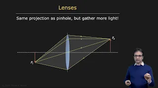
be much longer so that the detector that you're using to capture the image has enough photons that arrive on it and so you can imagine that almost for any real application of computer vision waiting for 12 seconds to capture a single frame is just not going to work and that's why we use lenses