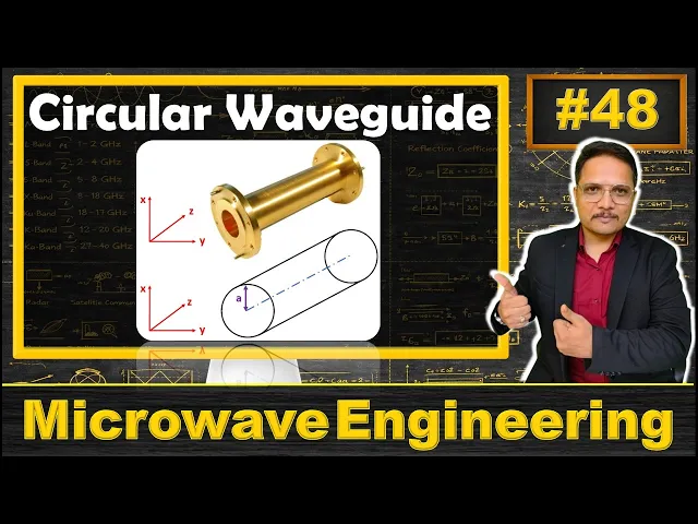
Hello friends welcome to engineering Funda family in this video I'll discuss about circular view guide before I start with my explanation let me show you how many points that I'm going to cover in this video see first of all I'll discuss about basics of circular wave guide after that I'll discuss about structure of circular wave guide after that I'll explain designing parameters of circular wave guide and at last I'll C applications of circular wave guide so let us begin this session with first agenda that is basics of circular wave guide circular wave guide is Hol
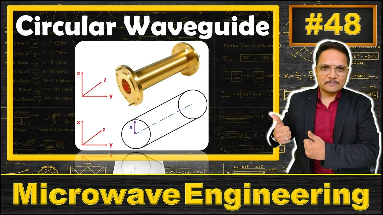
metallic tube and it is having uniform circular crosssection If You observe the structure then one can observe see this circular wave guide that is Holo metallic tube and it is having uniform circular cross-section right there are a few basic things that you need to note down the manufacturing of this circular wave guide that is easier compared to rectangular wave guide so as in when we fabricate circular wave guide then fabrication process that is easier with this circular wave guide compared to rectangular wave guide right and one more thing that one need to understand the joining
of this circular wave guide that is also easier compared to rectangular wave guide joining means you may be joining this circular wave guide with horn antenna or you may be joining it with some other circular wave guide right so that joining process that is easy compared to rectangular view guide right so here see with circular view guide one should know manufacturing is easy compared to rectangular wave guide and joining is also so easy compared to rectangular wave guide but there is one issue the circular wave guide that occupy more space compared to rectangular wave guide
the reason is it is having circular shape because of which it occupies more resultant space compared to rectangular wave guide right so as then when you have applications based on more towards space at that time we should be using rectangular view guide but if you don't have any con train with respect to space then one can go for circular wave guide the dominant mode of circular wave guard that is te11 this is very essential one should know this dominant mode of circular wave guard that is te11 and dominant mode of rectangular wave got that is
te10 dominant mode means what dominant mode means lowest cut off frequency so with circular wave guide we have lowest cut of frequency that is associated with te11 mode that is dominant mode right see it has more interference at dominant mode compared to rectangular wave guide with circular wave guide we will be having more interference at dominant mode compared to rectangular wave guide with rectangular wave guide dominant mode is there at te10 mode that is having very less interference compared to circular wave guide see interference happens because of fabrication of that circular wave guide as in
when you form circular shape at that time when you bend that metal in a circular shape at that time tapping issue will generate disperson inside circular wave guide like you see if you have flat surface if you have flat surface like this and when you bend surface like this so what happens is here in banding there will be more dispersion when signal is reflecting from the surface right so with circular wave guide there will be more interference at dominant mode compared to rectangular wave guide there are few more interesting points that you need to note
down like you see with circular wave guide if you have te01 and tm01 modes then those are rotationally symmetric so t01 and T M 01 those are rotationally symmetric so here when you talk about polarization then you cannot have any issues with polarization as these two modes are rotationally symmetric right but all modes are not rotationally symmetric one should know te 01 and tm01 these are rotationally symmetric mode with other modes there will be some issue if you don't have proper polarization right so with circular wave good this point that you need to note down
T 01 and T M 01 these are rotationally symmetric mode in circular wave guide T 01 mode that is having lowest attenuation so when you talk about different modes then with te 01 lowest attenuation is there so as in when you use te 01 mode at at the time you'll be having lowest attenuation and this mode is suitable for long wave guide transmission right and see with rectangular and with circular wave guide one thing is common see circular wave guide also allows te and TM modes only it does not allow Teem mode that is applicable
to rectangular and circular wave guide right so these are very essential points that one should know regarding circular wave guide now I'll discuss about structure of circular wave guide circular wave guide is Hol metallic tube you can observe circular wave guide that is Hol metallic tube that is having uniform cross-section that is having uniform cross-section and that cross-section is having shape of circle that cross-section is having shape of circle here with circular wave guide EM wave propagation happens based on total internal reflection here one very essential Dimension that you need to note down the radius
of this circular wave guide that is small a in different book they may be considering different notations but here I'll consider that Dimension as small a so that is how simple structure is there with circular wave guide one more thing that you need to note down regarding structure see here in circular wave guide we will be having shape of circle so if you talk about shape of circle right and if you talk about flat surface then in shape of circle we will be bending metal over here so tapping issues are there with circular wave guide
and because of tapping efficiency dispersion will be higher with circular wave guide right as in when you talk about circular wave guide it will be having higher issues of dispersion because of which there will be more attenuation right so compared to rectangular wave guide there will be higher attenuation with circular wave guide now I'll be discussing about designing parameters of circular wave guide designing parameters of circular wave guide is based on few very essential equations using this equations in future coming videos I'll be solving problems as well the first designing parameter is cut off frequency
of circular wave guide cut of frequency is xnp / 2 pi aunk of mu Epsilon see this X and P that is based on basil equation the function of Basils that is bit complicated one so you will be given with table and based on that table you will have to identify value of x and P so for a different mode based on table you need to identify X andp from the table for example with te11 mode xnp that is 1. 1841 likewise with different mode this xnp value that will change right here this small a
that is radius of circular wave guide and this V is velocity of EM wave one should know velocity of EM wave V the velocity of em w v that is 1 / root of mu Epsilon here this mu is mu0 Mu R and this Epsilon is Epsilon 0 Epsilon R here velocity of light in free space that is C and that is 1 / root of mu 0 Epsilon 0 so here remaining content will be mu R epsilonr and for free space for air mu R and Epsilon r that is one so velocity of EM
wave that is velocity of light in free space right but with different material mu R and Epsilon r that will change so here see 1 / root of mu Epsilon that is velocity of EMV right now based on this cut of frequency one can identify cut of wavelength cut of wavelength that is velocity by frequency if you take ratio over here velocity by frequency then you'll be having 2 pi a / xnp right so that is how one can have cut of wavelength of circular wave guide now if You observe here we have phase velocity
so phase velocity of rectangular wave guide and phase velocity of circular wave guide that is having similar equations right so phase velocity that is V / < TK of 1 minus FC by f s and guided wavelength equation is also similar to rectangular wave guide equations of guided wavelength that is Lambda G is equal to Lambda / root of 1 - FC by f s now here one more equation that one should know that is related wave impedance of circular wave guide the wave impedance is Theta into square root of 1 - FC by F
squ where this EA is free space impedence and that is 120 Pi so you can say wave impedence of circular wave that is 120 Pi into root of 1 - FC by f s so these are essential equations using which one can design circular wave guide now I'll be discussing about applications of circular wave guide the circular wave guide that is broadly used in microwave engineering few applications are listed over here like one can use it to connect horn antenna for feeding of reflector antenna so usually with reflector antenna we will be using hor antenna
as a feeding like if I draw a diagram here see we have reflector antenna like this and in the this reflector antenna here at focal point of this parabolic shape we will be using feed and as a feed antenna as a feed antenna we will be using on antenna over here right as a feed antenna we will be using on antenna over here and with this horn antenna you will be observing here with this circular horn we need to give Supply and that Supply will be given via this circular wave guide right so this circular
wave guide that will be connecting over here and one end of that circular W guide that will be connected with Supply so that is how on antenna that we are connecting it with this circular wave guide right see one can use circular wave guide for short and medium distance Broadband communication as well as te01 mode that is used for long distance transmission above 10 GHz and one should know in circular wave guard with te01 w we have minimum attenuation so with that mode one can have long distance transmission as well and above 10 ghs of
frequency that we prefer with that mode I hope you have enjoyed this session still if anything that i' like to share just note it down down in comment section I'll be happy to help you thank you so much for watching this video