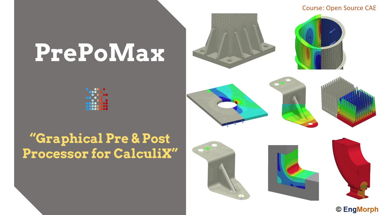
hello and welcome to my first tutorial about prepo max which is an open source pre and post processor for also open source finite element analysis server calculates premix is under constant development and new versions are released frequently i have included a link to the preparamex homepage in the description of this video there you can find a download section a list of currently supported features a user's guide and more and the forum should be available there soon as well in this first tutorial i will show you how to perform a basic simulation people mix you'll certainly
notice that the software is extremely user friendly and it doesn't take too long to learn how to use it especially if you're familiar with a backup workflow the first analysis is simply supported beam subjected to elastic bending this is one of the most common cases for simulations carried out by people who start learning how to use a new fee software and there's a reason for that because such analysis can be quickly and easily prepared and they yield really predictable and verifiable results a prep max doesn't even require installation you can use it right after downloading
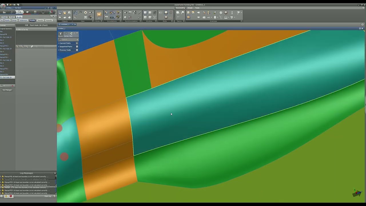
and unpacking the files now the first thing to do is to create a new module so let's go to file new and now we have to select the unit system i will choose the one with millimeters and and now and the next step is to import the geometry file import and that's because people max doesn't have built-in modeler but you can use any cut software you want and import the file in universal format such as step ig or stl the remaining formats are from meshes if you don't have access to commercials cut software you can
use freecad which is a very good tool it's an open source code but meant primarily for cat modeling and you may also notice that it has a finite element analysis module as well um and what's interesting this module also uses calculates just as prepomex as its main solver i think that i will prepare some tutorials about freecad fan module in in the future so i will show you how to perform some basic simulations here as well but let's go back to the preponex for now i will choose the step format which seems to be the
best choice uh for import of the geometry in the software and now the geometry is imported and a good practice is to check whether the dimensions are fine because in some cases the geometry after imports may be somehow scaled or after export from cad software so it's good to make sure that everything is fine you can use this ruler here to estimate the size of the model or another way is to use the query tool and distance and here you can pick any two points and the software will display the distance between those two points
it's a very handy feature not only for checking the geometry after import uh but also you can use it to for example check the dimensions of the model if you are not sure what they are and you for example you want to define mesh sizes so you need to know that approximate size of the model okay now the next step is to create a mesh because without mesh you can proceed to the next tab of the model tree in this first step we prepare the geometry and mesh then when the mesh is prepared we go
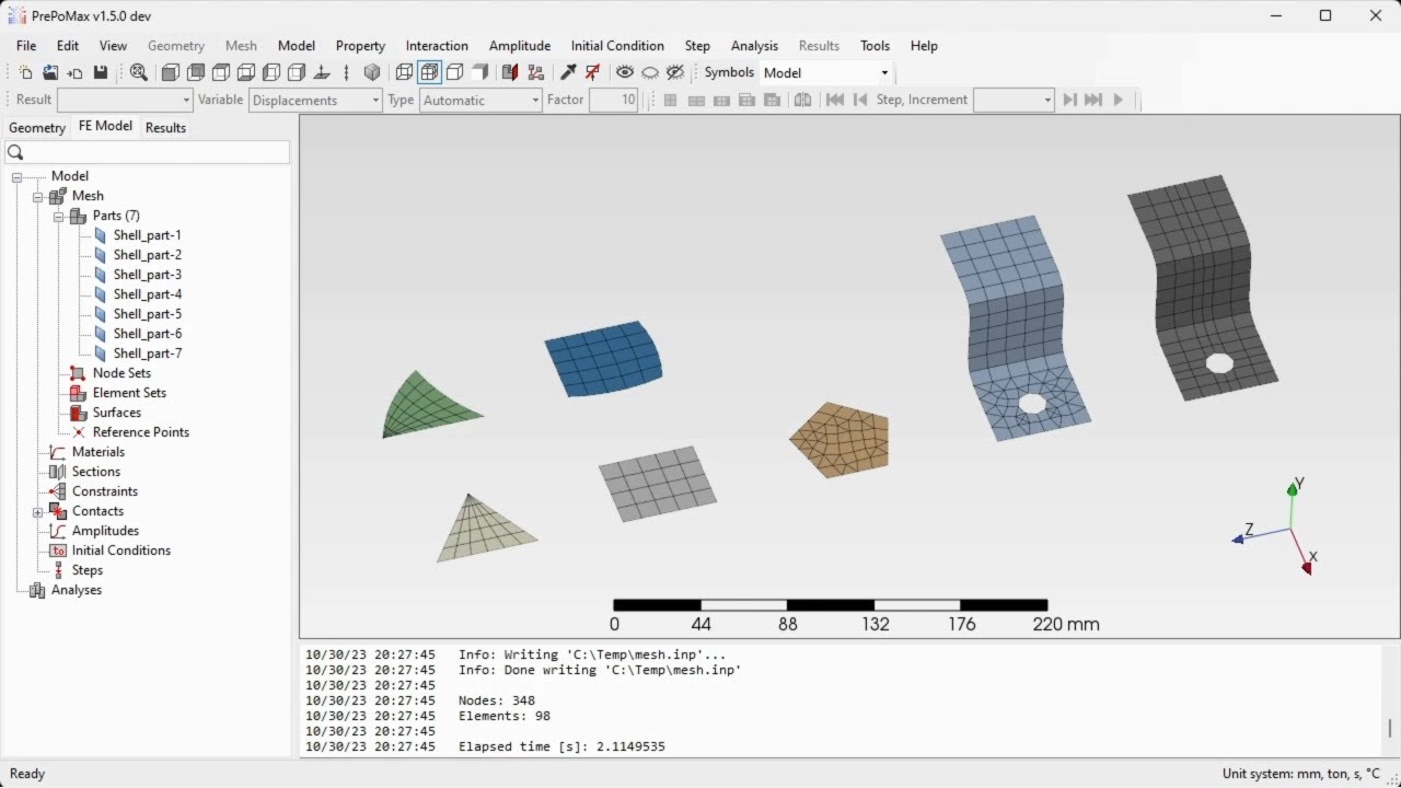
to the second tab set everything for the analysis and then the last step is for post processing but now let's go back to the first step and define the meshing parameters in this case i will use 25 millimeters for maximum element size this button here allows me to preview the mesh before it's created and when i click ok and this will be applied and now i just have to create the mesh tool and to proceed to the second tab the software kit mesh automatically here are the basic statistics of this mesh and you can now
we can proceed to the second stage of the analysis preparation which is uh setting all the noise features basically there are two approaches two possible approaches in people max to do this the first one is to create note element sets and surfaces first you can name them in any way you want for example fixed and you can define note sets this way this is the surface base selection you can also speak edges and vertices this way but you can change it to a part selection which will be called the nodes of the parts and you
can use more advanced types such as select with box tool you can pick desired notes the same applies to elements and it's also similar for surfaces so the first approach is to define those first and then use them for definitions or the second approach is to uh just proceed directly to definitions and the software will create notes as elements sets and surfaces automatically in this case i will use the second approach for two reasons the first one is that i want to do this the faster way and the second one is that i want to
to show you that it's really not necessary to define those things before proceeding to boundary conditions and loads because in some other programs it's necessary it's not the case in people max basically if you wonder why you even use that the first approach with the defining everything first and well this this approach might be better if you want to have more control over the model in some cases it's better but in this particular case i will use definitions created automatic without automatically created sets and surfaces okay now uh the first thing to do is to
create a material uh let's provide a name for this it's not necessary you can leave it by default but it's a good practice to provide names for any features you define if you have time for that of course so let's define elasticity and first property is young's modulus and now we have to specify croissants ratio as well so now you can proceed to sections if you know either calculus or abacus or both and then you know that the concept of sections but otherwise you may not be not you may not be sure what what it
is i will just give you a basic explanation those are basically sets of of properties that can be applied to finite element models they describe the elements in terms of of their for in the case of solid section this is just a material selection but in the case of shell section for example you would have to provide the thickness and if it was a beam section beams are currently not supported in prepondex but if it was a beam section then you would have to define a beam profile for example yeah so that's those are the
properties of elements you can you can call it this way um and now let's choose the whole part apply a section to it and confirm now we won't need constraints contacts and and all those things here so i will just create a step this will be a static step with all the default settings i won't describe the other steps here because they are not important for now and now when the step is created i can define boundary conditions and loads um so let's start from boundary conditions as i said the beam is simply supported and
i can use the fixed boundary condition here because it applies it fixes all the degrees of freedom but i will choose the the one displacement rotation where you can define boundary we can define boundary conditions for individual degrees of freedom as you may know solid elements don't have rotational degrees of freedom i will pick the first edge here by the way you you don't have to use mesh all the time you can hide it and operate on geometry which is also interesting because in many other programs you have to operate on mesh and when defining
boundary conditions loads and all that stuff but here you can hide the mesh and work on geometry but the mesh has to be created as i said before so now i'll choose fixed option you i could also use the zero millimeter one uh because it's basically the same uh what you can do if with zero with this third selection is that you can specify some value and turn it into a enforced bound for displacement boundary conditions so and that's why why this option is here but the fixed is basically a predefined way of of constraining
the degrees of freedom i will do this for those three translations here and now the boundary condition is defined for this edge uh i will do the same for under this edge here and i will choose the first and the first two degrees of freedom uh i will just leave the the third one because we want this to be a roller support and the z should be unconstrained okay i can confirm this now and what i have to do now is to create a load of course and here's how the beam is loaded this is
a simply supported beam with uniformly distributed load and the value is 2 megapascals i will show you the this sheet later on because this it contains analytical results so let's apply a load pressure type to this surface and it will be 2 megapascals i can confirm this now i could also name this but it's not necessary as i said and so basically the model is now prepared so we have material section boundary conditions and load so we can submit the analysis now but before i do it i will show you that in settings here you
can select the number of processors to be used for analysis because you will if you have multiple cars you you will want to do this to make sure that analysis runs as fast as possible in this case i have this configured so so i don't need to provide this again this will be remembered for for future sessions in in prep max i would just click right button and run to submit the analysis confirm that i want to override the remaining the previous results and here in this monitor you can see the output status of the
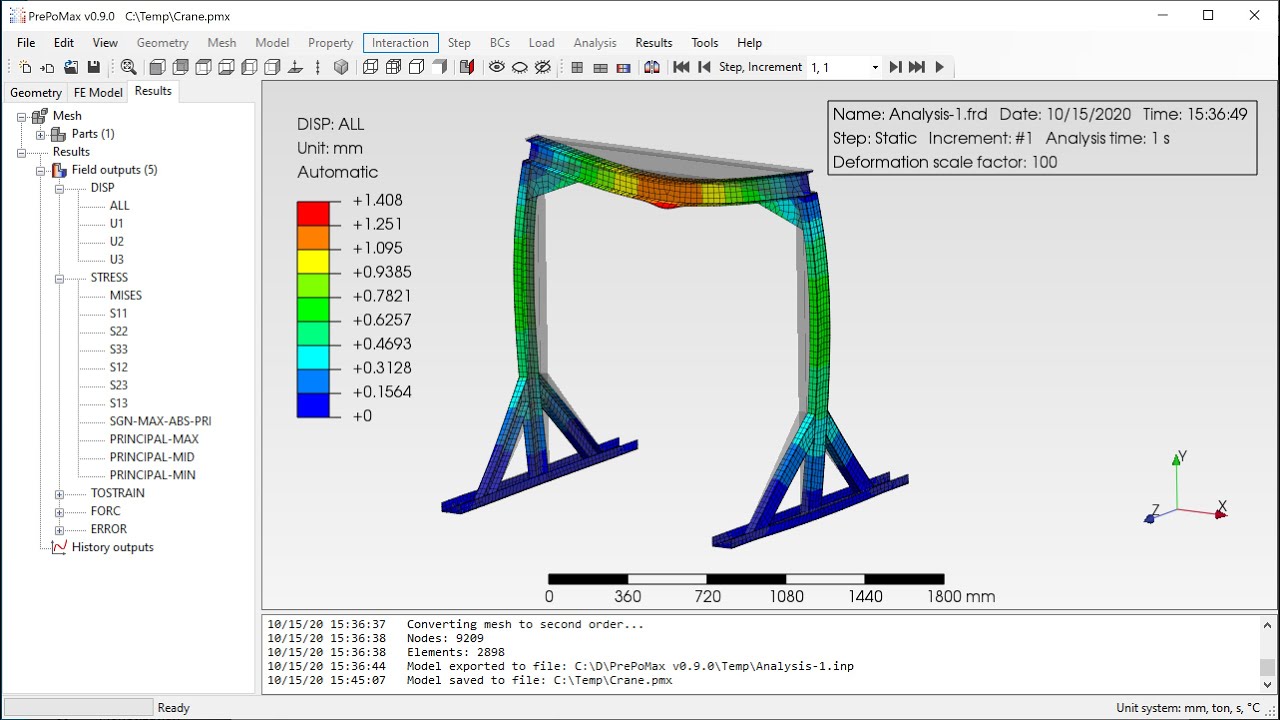
analysis convergence information everything is in this job monitor here and with this button i can go to results or i can close it and go to results this way so now i have the results for this analysis and what we'll start from is making sure that all the settings for post processing are in a way that we want i have this already configured but in your case if you just downloaded the prepayments then then you will most likely have to adjust all the settings for post processing here you can select the scale factor in this
case it's automatic i could also use true scale or user defined deformation scale or turn it completely off so that the model is not deformed i could also draw the deformed model here so you see that it's outlined and what's what's so more i could also show the locations of maximum and minimum values in of selected variable but again i will turn this off and we could also set some we could also set the legend those there are several types of the legends in most cases you would use the the rainbow one but there are
other types if you if you wish here you may want by default you will have the scientific type of number format and this might not be very um user friendly i would say uh you i mean many users of finance analysis software get used to it but if you want to use the easier to read format you can switch to general of course for example in case of very small or very large quantities such as often strains or displacements you may want to use the scientific one but in this case we'll stay with the general
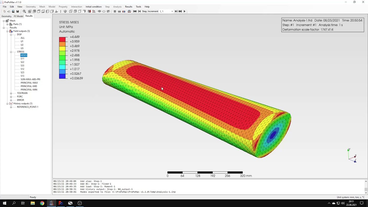
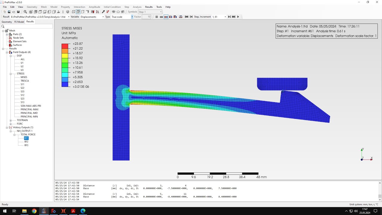
type and you can also you can also set the range of the legend and other stuff here which will not be necessary for for this moment okay now that we have the the results we should take a closer look at them and make sure that they are correct so i will go back to the sheet here where i have the analytical results calculated using classical beam fury and here are the maximum stresses that are expected in this model uh it's 150 megapascals so let's let's check this and let's here you can display it from misses
stress but i will go straight to normal stress in the third direction and what is what's interesting you can use the query tool and the one that we used before was distance but this time you can use point node and this will show you uh basically to work like a sensor or a probe and we'll show you values in in selected locations for selected nodes uh here you can notice that the values are very close to analytical results which was 150 mega pascals so you can query them the stresses in selected locations of the beam
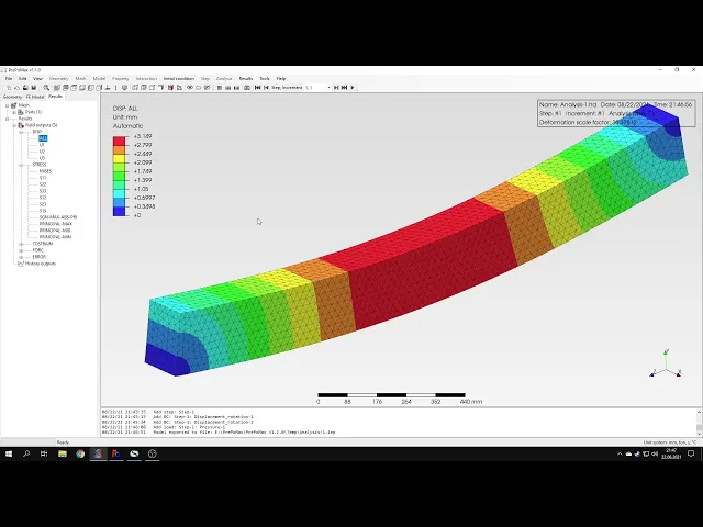
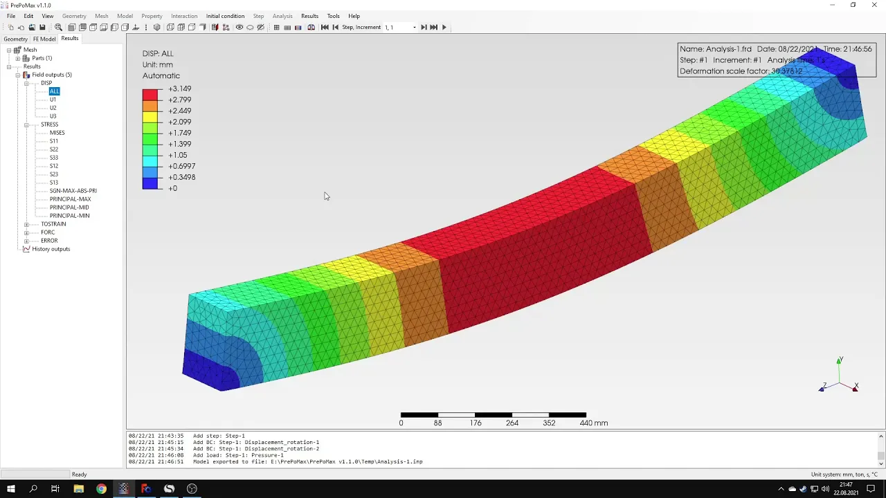
and now i can i could also highlight the elements to see their ids and there are other options which i will not discuss in this case okay so we could confirm that stresses are a good agreement with analytical values so now let's go to displacements and the displacement here is expected to be 2.97 millimeters so let's check this um let's go to displacement in the second direction which is y axis uh and let's query them the displacements here in the middle of the beam as you can see the value is higher than expected by analytical
solution because here it states that it's over three millimeters while here it was 2.97 millimeters but as you may know and such differences between numerical and analytical solution are really of common and of course the the solution in case of numerical model depends on the mesh size quality and type of elements there are various features very various reasons that can cause the discrepancies here but the difference is not really large um so it's nothing to see nothing serious here it's just a small difference between analytical and numerical results and it's especially not so important because
we use those analytical values to make sure that the results are correct that we defined everything correctly we didn't do any mistakes and it's just for that to make sure that everything is working fine and that the solver gives us correct results which is also a good approach when using a new fine terminal analysis software okay that's it for processing of this simple analysis i think that the rest is is not so important here i can show you that you can do the section cut you can select any plane and this will cut for the
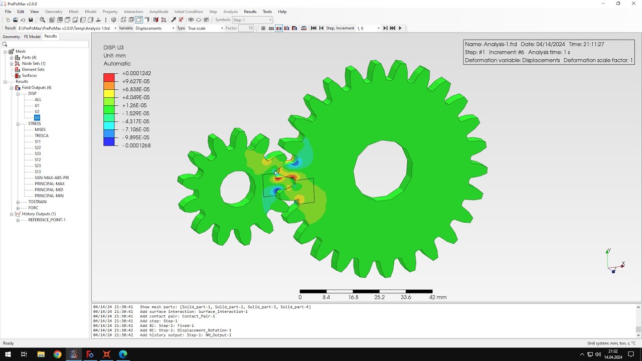
the beam which is also an interesting feature and but it's again not not so so important in this case in the next videos i will show you much more advanced cases here it's just a basic analysis to show the basic capabilities of pre-comics but i plan to to do several more tutorials where i will show you how to prepare more advanced analysis so that's it for for this first pepomex tutorial feel free to ask any questions and suggest topics for future tutorials in the comments for now thank you very much for your attention and have
a nice day and see you in the next video