thank you [Music] okay so officially welcome you all to this course next signal IC design right so as per the convention so let's first uh let me first give an introduction and motivation to this course right and I mean the course title is Nick signal right so what do you think uh it is meant by mixed signals yeah basically that right I mean again if you again to give a broad introduction I mean if you take any signal which is it represents any physical quantity usually the deal is we convert any kind of signal to
electrical signals like voltages or currents simply because you can easily process electrical signals right I mean you can't add two temperatures but you can add two currents easily and that's why you have all these sensors for right and if you take let us say some voltage signal like this so uh with time it's going to vary so let's say it does something like this so the information here is contained in time or in amplitude amplitude Okay so then I can have another signal which are same amplitudes but stretched in time no is it the same
signal so where is the information contained that's what the information is only in the amplitude I can have a similar signal with the same amplitudes but stretched out like this but that's not the original signal right it's it's both in time and amplitude Okay so if you take any signal you need to make sure you know what the signal level is at different time instance right because we have we need both these node things so this is time and amplitude and the physical uh the signals we encounter in the real world they exist for all
possible values of time and similarly they can take any value in this y axis and they are basically the you know continuous time and continuous amplitude signals as you know and they are the analog signals right but of course if you want to store if you want to store such an analog signal you will in principle have to save its value for all possible values of time right of course that's not possible so what do you do yeah basically you try to save its information at discrete time instance say like this right and usually make
sure these time periods are uniformly spaced so which means you don't need to save the timing information separately right because the moment I know what rate at which I have stroked the signal I simply know the time instance also similarly in the y-axis instead of sharing all possible amplitudes I will say I'll take a range of amplitudes I'll say any amplitude within this range I'll round it off to some other amplitude within here see here I'll do it for all you know amplitude ranges so then I'll end up with the finite number of amplitude levels
to store and this you know it can encode using you know binary bits and this what gives you your discrete amplitude and discrete time discrete amplitude signals which is the digital signal as you know right and of course to convert from this analog to digital you can do in two ways you can either first discretize the time and get a discrete time continuous amplitude signal and what is this process of discretizing the time axis called sampling I'm sure everyone is aware of that and once you discretize the time axis you can go ahead and discretize
the amplitude axis and what is this called yeah I'm sure you would have heard this term in some form of the other I mean the other way is to you know first discretize the amplitude axis that will basically give you a uh continuous time discrete amplitude signal and then you can go ahead and mathematically you can do you know anything right you can first sample and quantize or quantizing sample but of course in practice it's much easier to sample first and quantize later that's all if that is much easier to do in practice so that's
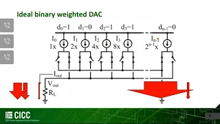
what it's done in most cases that is what is done at least right and of course again you'll also want to convert from digital to analog so you can do something similar and these circuits which basically deal with conversion of signals from one domain to the other they are called Data converters okay and of course the uh one that converts analog to digital I'm sure you know it's called analog to digital converter ADC and this is the symbol for the ADC okay I mean the deal is so analog signal is the input so it's just
single channel so one line output is digital so we'll have you know a fat Lane pointing there is multiple digital bits there similarly for the dark dark is the digital to analog converter right so now we have established what will be the focus of this course the next question is okay what is the Practical relevance of this now again as with any circuit design course to give a practical example of for practical application of any circuit what is the big best example for application of circuits you might have heard in multiple classes right in circuit
design course what is the best Real Life practical example you all have in your pockets smartphones okay I mean even before that as a live example right I mean this lecture is right now being recorded in my Note Tablet it's going to get uploaded to the cloud or something and it's all a strings of ones and zeros but what I'm speaking is an analog signal right so obviously here there is an ADC that is in between digitizing what is being spoken and storing it similarly when you are playing it back on your smartphone or you
know laptop you will have a duck right and of course your smartphone is much more smarter than this it has more features and I will call it as a warehouse of you know radio transceivers and if you take a radio transmitter I mean audio guess however of how many of you have taken some course on digital modulation or aware of digital modulation okay or even if not it's OKC if you take any transmitter all modulation now it's all it all happens in the digital domain so this is a digital modulator but the signals you might
want to transmit they most likely will be analog signals so what do you do you first have to have an ADC to convert it and then you do the modulation and of course you can't directly transmit your digital signal so you'll have to convert it to an analog signal and then you convert up convert it in frequency and then directly transmit it of course in practice there are whole lot of other blocks in between to make this functional but the Bare Essentials of any radio transmitter are these okay again if you look at the radio
I mean mobile receiver to receive the signals you need to have an antenna and now your antennas not going to receive the required signal alone it's going to pick up all sorts of stray signals everywhere so how do you get only this part from the signal you'll have to do some kind of filtering yeah it's a band pass filter so you will have some filtering here and once it's filtered you again down convert it you digitize the signal and demodulate okay this is demodulated okay and as you will see later I mean this down conversion
can also be combined as a part of the ADC so in principle again the bad Essentials here are an antenna filter and an ADC again as of now we need more blocks in between to make this a functional receiver but these are the bad Essentials and upon I'm trying to get at this in a radio transceiver data converters play an essential role right and you know your mobile phone has a whole bunch of them like say one for Wi-Fi GPS Bluetooth NFC and multiple standards right 2G 3G 4G 5G and whatever you have and not
just that when you have your touchscreen you know the touch screens are all capacitive that's right and again Loosely speaking it's like a crossbar structure like this and the idea is whenever you make a touch the capacitance around that location is going to change right because you know the chambers are going to move and because of the capacitance is going to change and the change in the capacitance is what is sensed to detect if the touch is made or not and how much the capacitance changes determines the sensitivity of the that's right you have this
pressure sensitivity nowadays so it is not just enough to say if the capacitance changes you also need to know how much the capacitance has changed and again for sensing this you have an ADC here so if you have your touchscreen controller it's again going to have a whole bunch of adcs and I mean other example is I mean all this you know gigabit Ethernet or in your phone USB type c you had old type A type B type c and with evolving generation the data rates has been increasing right and the reason is because we
have been able to pack in uh complex or denser modulation schemes and the fact that we have been able to design faster and faster adcs with a higher resolution and here you can have ADC sampling at hundreds of gigabits per second and every time you make a file transfer through USB or you know LAN ads are operating operated in parallel so the again the point is if you take your phone it houses a whole lot of adcs and the specs are all broadly different right for example the specs for a touchscreen ADC touch screen ADC
they'll have a very high resolution but the bandwidth will be very small now if you come to a radio receiver it will have a medium resolution but relatively high speeds and when you come to your you know serial links like USB or you know LAN it will be ultra high speeds but really low resolution okay and I mean not just you know mobile phones right I mean if you go for any health monitoring system sorry resolution I mean the number of bits we'll come to that later yeah yeah so let's say you take a thermometer
digital thermometer right it gives a digital reading why because it has an ADC in the background now every you know you have smart watches that can detect every kind of Bio signal and gives a digital reading right again there are a whole bunch of adc's operating in parallel to give them right right so yeah next time remember that when you're opening Netflix and watching something the moment you're touching your phone an ADC is operating signals right so yeah so now that we have established adcs are sort of around us everywhere let's get straight to the
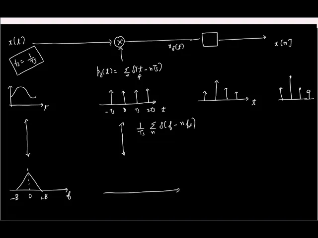
course so let's start with the first topic so again uh as you know the first operation in digitizing a signal is sampling so let's start with sampling I'm sure you guys have learned about sampling so this is supposed to be a refresher so sampling basically takes you know continuous time signal say x of t and after you sample you get a discrete time sequence X of n that's all and it's assumed that you are sampling it at uniform time instance space.ts so right so if you have signal like this after sampling you take only discrete
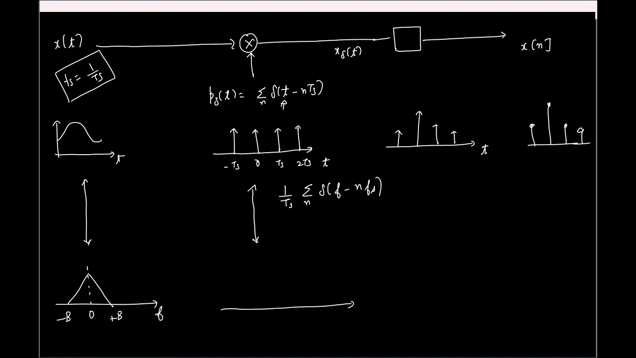
no time points like this so great so let's understand this in frequency domain also and for that I'll try to model uh sampling operation mathematically and by the way how is sampling modeled mathematically multiplication by train of impulses right so if you have a signal X of t the idea is you multiply it by a train of impulses say I'll call it some T Delta of t this Delta of T minus right so uh in time domain let's say you had something like this so this will be a periodic train of impulses let's say this
is 0 minus t is okay so the output is going to be a signal so let me Mark this here so we'll have something like this let me call this some X Delta of t now this x Delta of T is it a continuous time signal or a discrete time signal okay I mean see remember discrete in time simply means that the signal is not defined for any other time instant it is only defined at specific time instance but here what is the axis here here it is T here it is T here also it's
continuous time yes I mean the moment I have P it's a continuous variable right so this is still a continuous time signal so of course to get the sequence which is a display time sequence like this to be uh really accurate you need to have something here mathematically speaking that takes in this continuous time impulses and puts out discrete time impulses like this again this is just a mathematical modeling that's not simply how it's done in practice right in practice you just look at the signal value at specific time instance and just done this is
just for the sake of modeling so let's now look at the uh Spectrum so let's say this guy The Continuous name Fourier transform of this is something like this see it's a minus B2 plus b this is zero what is the Fourier transform of a periodic brain of impulse it's again a periodic kind of impulses right and it's scaled by 1 by TS I'll not go into the details you can work it out it's n times FS where FS is one over TS okay fine so if I plot the Spectrum it's again uh will again
be a train of impulses like this I'll just Mark couple of them oh so in time domain these two multiply to get the signal so what happens in frequency domain it just simply convolves so we convert these two what do I get I am sure everyone is fine right I mean basically if you convolve this with a plane of impulse you are going to have shifted copies of the same signal around that frequencies where the impulses are located fine so we'll have something like this it will be scaled by 1 by TS so 0 so
this is basically X Delta of f so now let's say I'm interested to find the discrete time Fourier transform of this discrete time sequence so let's quickly see how we'll do that so let me go to next page so let's say I have the sequence X of n I call the discrete time Fourier transform of say x d of E power G Omega how will I compute huh I mean if I have a sequence X often how will I find the discrete time Fourier transform X often okay fine wait and uh remember that we all
our goal is to find the Spectrum from the spectrum of X Delta of X we already have this guy spectrum of the signal we are trying to find what is the spectrum of this that's all right and I'll write this uh X Delta of T in a slightly different way so X Delta of t is basically X of T times C periodic 10 of impulses so if I multiply if I take this x of T inside the summation what do I get fine right so this is now X Delta of t so if I were
to write X Delta of f the Fourier transform of this signal what will it be no no I mean yeah that's what we got here right I mean we already got it has like this I am trying to find out another expression for this from here okay see here if you see the signal is basically what a bunch of impulses but with different areas right so Fourier transform of linear operation so I can take it in X of NTS is the scaling Factor now I just need the Fourier transform of this guy what is the
Fourier transform of shifted impulse yeah I just E power minus J 2 pi f it's on the same as a signal this is same as a spectrum we derived earlier but this is in a different format that's all so now if you compare these two things might become apparent so we already have the spectrum of this we are interested to find this guy so if you compare these two what do you think I should do to get the discrete Spectrum I mean if you see the only difference is I mean X of n is X
of NTS there is no doubt yeah Omega should be replaced by this guy right here I have omega n left side I have 2 pi f n t s so I'll replace Omega or the other way is I'll replace 2 pi f t s by Omega I mean the same thing you guys know right if you have a continuous time frequency f then you sample it at a frequency FS the resulting discrete time signal will have a frequency which is 2 pi F by FS the same thing again and again so okay so let's say
let's get some values if continuous time frequency zero what is uh corresponding discrete time frequency if it is FS FS corresponds to 2 pi f s by 2 is pi so on right great so again the only thing we have to do is in this spectrum we just have to replace the frequency axis by an Omega that's all just changing the frequency axis nothing else right so let's draw that quickly hold on so this is F this is X Delta of f the scale by 1 by T is so the display time Fourier transform is
going to be same nothing changes in amplitude so only the frequency will scale so f s corresponds to what frequency in discrete time required two pi so this is my x d of equality right it's the same old right I mean you know discrete time Fourier transform is periodic with 2 pi okay cool cool so now we are at this let's uh reprove the obvious so let us say I now uh let me push it down first exclusive yeah so let us say here I reduce the sampling rate FS I keep reducing the sampling rate
FS what will happen so this replicas will start to come closer and Beyond a point what will happen yeah so they'll start to overlap like this and the signal gets corrupted and the technical name is called aliasing so we'll come to that so let's say if I call this minus B and plus b what is this frequency first minus B right so to prevent aliasing of course you know f s minus B should be greater than b so this is what Nyquist told us centuries ago or maybe decades ago and this frequency which is twice
the signal bandwidth is often called the nyquistade that's basically the minimum frequency at which Nyquist recommended us to sample any signal right great so okay now let's look at the same effect in time domain also quickly so I'll take uh some signal X of T which is say cos 2 pi Delta f t let's say Delta f is very small and I'm sampling it at FS which is much much greater than Delta f what will be the discrete time sequence I get um yeah basically I'm when it's sampling it I'm just replacing the time by
NTS that's all right so this is basically cos 2 pi Delta F I am taking the values at NTS and I'll just write it as n by FS fine I mean just again boils down to same thing right I have a continuous time frequency Delta f after sampling at F is it results in a sinusoid in discrete time at a frequency 2 pi 2 pi Delta by FS fine cool so now let us say I have a another signal say cos 2 pi FS plus Delta f t I sample it at FS what will be
the resulting sequence will get the same is that okay you can work out the same thing right you can replace you know T by n by FS and you will still end up the end up with the same sequence is it okay to everyone right I mean this is basically the issue of which one this one this FS right here that's I mean the duster I'm just mentioning the rate at which it is sampled it's okay just for you know under its you can either put TS or FS doesn't matter so this is the issue
of aliasing you know where if you don't sample it fast enough high frequency signal may look like it's a low frequency signal in after sampling so cool so now if I sample at a frequency FS what is the maximum frequency that can be sampled without encountering Lac FS by 2 is that okay so maximum frequency is FS by 2. so let us say now we have a signal a sin isolate f s by 2 plus Delta f this is beyond the maximum frequency I mean that will not you know result in aliasing so if I
sample it at FS will there be aliasing or not sorry okay I'm just saying see the uh let me rework you through the argument see if I have a sampling rate of FS so max frequency that can be sampled without causing aliasing what is that they find I mean it's just I mean you know inverse of Converse of Nyquil sampling theorem right so I can sample the frequency of FS by 2 maximum without resulting in aliac so my question is now uh let's say take a sinusoid at a frequency f s by 2 plus Delta
f I am sampling it at FS will this result in aliasing yes so what will be the you know I mean frequency to which it will Alias to okay multiple options FS by 2 plus or minus cannot be the case right FS by 2 plus is uh see when I say if it aliases it should Alias to some frequency less than FS by 2. right something yeah so again you can work it out I'll just give you know I mean the way to think you see this frequency when you sample it it FS will result
in some discrete and frequency Omega now if I take the same frequency I do plus or minus f is for example interface I'll get the same Omega right so if I just take minus FS here and this basically simplifies to what fine of course real signals will have equal content in the positive frequency and negative frequency so this basically FS by 2 minus Delta n right so basically if you are sampling at a rate FS let's say if this by 2 here this so any frequency or this range of frequencies from f s by 2
to FS it will Alias back here right so this frequency FS by 2 plus Delta f is going to fall back here to f s by 2 minus Delta l yeah that's what I'm saying right it's a negative frequency but real signals will have same content and both positive and negative frequencies is that okay so I mean by the same sorry okay okay is this point clear if you use this point clear that if you have a tone at f s by 2 plus Delta f then you sample it at FS it will Alias back
to FS by 2 minus Delta f is that point clear or not okay you can work it out I mean I'm just giving a simple explanation see let's say first by 2 plus Delta f and you sample it at FS you'll get some discrete time frequency Omega what I'm saying is even if I add or subtract FS from that I'll get the same frequency Omega because that's what we saw here right isn't it so if I subtract FS I'm going to get the same so that results in Delta F minus f s by 2. and
it's a negative frequency so you should have a positive counterpart and that is FS by 2 minus Delta right so if that's what is generalized here so if you have a tone at f s by 2 plus Delta f after sampling it will fall back here to the left side the same spacing I'm sure you know right if you have a tone at FS when you sample it at FS what is the frequency to which it will Alias to so you have a sinusoid at FS you sample it at the same rate FS what is
the frequency till Alias back to zero right I mean I can see from here right I mean FS will fall to zero I mean other thing is I mean you can see in time domain so this is exactly like this this is a sinusoid at FS you sample it FS you will get a constant DC signal right cool so probably I can show some examples so yeah so this is an example where I have strictly obeyed Nyquist condition so I think the sampling rate is 10 Hertz and I think my input is one Hertz so
the yellow curve you see that is a continuous time signal and the blue dots are the discrete time instance that have been sampled and it seems like it's not an issue now of course I am taking the another case where the sampling rate is same but this time my input frequency is I think 11 Hertz so if this is 10 Hertz to finish 11 Hertz so what will be the frequency to which it will Alias back to 11 Hertz signal sample at 10 Hertz plus Alias back to one Hertz and that's what you see right
I mean the yellow curve is the learner signal I am sampling it at 10 Hertz and the blue dots or the you know like sample points and you it looks like it is of a low frequency sinusoid and the period is also you see it's one second one Hertz okay so this another extreme case of aliasing that I think again FS is 10 I think my FN was 111 Hertz so again what is the frequency to which it will Alias back to huh what hertz is it okay so it launch the Alias back to one
Hertz so again that's what you see here the sinusoid with a period of ones and of course a more cool demos aliasing is in photography right I mean you would have seen cases where you know the rotors of the helicopter doesn't move at all or you might have seen videos where you know uh of you know water dropping from a tap where it looks like the droplets are moving up I mean the same thing because basically if you have a tab water droplets are falling down videos basically you know samples of multiple images played at
some rate right if you don't sample it if you don't capture that fast enough to look like first you know this droplet is falling and then you might capture an instant where the droplets are here right so it will look like as though the water is moving up other thing is the fan right if you try to capture the motion of a fan or helicopter rotor using a camera and if you make sure that the speed of the fan and the frame rate is synced it will appear as though the fan is not moving at
all right basically the moment it completes one rotation like this you take one snapshot here another snapshot here another snapshot here so fast moving signal little appearance so it's not moving at all huh yeah cool so that is clear so let's look at this so let's say now we have this is the frequency axis let's say this is minus B to plus b let's say this is FS yeah okay let's say I'm sampling a signal at rate FS and uh let's say I'm interested in a band of frequencies from minus B2 plus b right so
the question is what is the minimum frequency I mean of course let's say now the input has all frequencies okay when I am going to sample it I'm sure that will be aliasing because simple does all frequencies what is the minimum frequency which can potentially Alias back to this band it's greater than fsb2 but what is the exact I mean assume that FS is much more greater than b right I mean 2B for Simplicity right can maybe draw it in a more realistic okay it's a b okay uh uh why do you say that I
mean yeah very good yeah I mean see I'm sure what happened everyone knows that if I have a frequency interface S2 zero right now I wrote it inverse hold on this is plus B minus B so here if I go to the left of it what is the uh minimum frequency which will Alias back right so FS is going to come here any frequency here will go here and the minimum frequency is basically FS minus B f s minus B will fall back here right any frequency here is not a problem from B to f
s minus B is not an issue because it is not erasing back to your frequency range of Interest they are also getting Alias for sure but our goal is to see if they are getting aliased in the required band of frequencies which will not happen so Point Clear so this band of frequencies from around FS with a bandwidth of 2B so this band is what Alias back here minus sorry yeah yeah I see yeah technically speaking it's minus B but for real signals minus b or plus b doesn't make a difference I mean even there
if you recollect it was I think Delta of minus f s by 2. but the logic was for real signals the negative frequency same as positive frequency right I mean COS of minus f is cos F sine of minus f is minus sine of just the phase shift the frequency is same so it could be a band of Interest let's say I'm looking at this is a bandwidth which is of interest to me is this point clear so if you are interested in a band of frequencies from minus B to B frequencies around FS will
what is will what will Alias back and that band is f s minus B two f s plus b right similarly uh it will not stop at FS right D1 somewhere around 2fs this band will fall here and so on somewhere else that you can work out okay great so this this is clear so let's say here uh when this lecture is getting recorded we are recording basically an audio signal right what is the maximum frequency or bandwidth of an audio signal let's say 20 24 kilohertz so let's say open Nyquist condition and Sample it
at say 50 kilohertz so we directly take the signal and Sample it will it work or before see any issues yeah I mean these are sorry your signal might be band limited to let's say the required bandwidth but when you are sampling the signal it is not just the signal alone you will have all sorts of stray signals if not you will have electronic thermal noise just omnipresent at all frequencies for us so by the same logic sorry so this band of frequencies around FS 2fs three of us everything will sort of Alias back right
and after sampling what you will see is you will have signal of course but it will completely get round with noise right you'll not be able to recognize the signal at all because you have Alias so much of noise that the noise is dominating the signal is a point okay Okay so we have a sinusoid at 2fs if I sample it at FS where will it Alias back to yeah so I mean you can if you're confused you can always do this right cos 2 pi this is the signal I am sampling it at FS
m that is it getting Alias back to PC right I mean water happens at FS is not some you know like you know some pure number right multiples of papers also have the same property foreign signal has a band Limited Spectrum like this it is only after sample you will have the replicas no no when you after sampling model you have that right see we have continuous time signal sorry I'm sorry hold on see your continuous change signal is band limited to minus B to B input right when you sample it you will have the
replicas right now the thing is along with the input you will have noise right and the noise will also get aliased here that's all right so we'll have I mean it's not a rectangle you will have yeah you'll have a complete noise I mean remember that after sampling the spectrum is periodic from in a discrete to frequency range 0 to 2 pi or minus Pi 2 pi or from minus f s by 2 to plus f s by 2. if you are looking at continuous time frequencies so whatever Spectrum we have that's just going to
repeat is this clear so if you directly sample the signal noise from multiples of FS from around multiples of FS they will Alias back to your required signal band and it will drown out your signal so what is the solution to this I mean see this noise is present along with your signal the issue is because your signal is nicely band Limited but when you're sampling interface you're allowing signals from higher frequencies to Alias back so what can you do right is it point clear your my signal is band limited to minus B to B
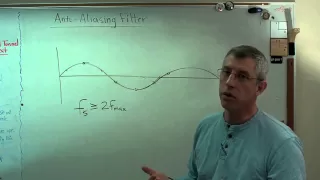
the issue is because noise from higher frequencies are falling I'll just filter it off in the analog domain right so before sampling you always have to have a low pass filter in this case a low pass filter high frequencies okay and this is often called the anti-alias filter for obvious reasons fine so sampling is always preceded by a low pass filter or a relevant filter to make sure you don't you filter out all the things that can Alias back cool so now let's look at some yeah so let's say again my band of frequencies of
interest is minus B2 plus b this is FS so uh the anti-alias filter which is a low pass filter in our case let's look at how its characteristics should be what is the range of frequencies it should completely pass right so this is it should have a flat response till this and it should provide sufficient attenuation to anything that will Alias back and what is the minimum frequency which can Alias back here perfect yeah FS minus B this is the minimum frequency which can potentially Alias back into my band of Interest so my low pass
filter must provide sufficient attenuation to this so it probably should have something like this okay I mean it's a frequency I mean it's a low pass filter right it's frequency response will be there forever right I mean I mean you should make sure that see this this should be at least attenuated by sufficient amount if this is attenuated by sufficient amount all the other bands will also be sufficient yet anyway great so now let us say I strictly obey Nyquist because Nyquist was a smart guy so I choose FS to be 2 times V so
this is f minus B to B so here the band of frequencies which can Alias back is FS minus B2 FS plus b right if I choose f s to be 2 times B what is the band that will Alias back of course the low pass filter must allow this B2 to B right so basically I need to filter off anything beyond B so the characteristics how should it look like should basically drop immediately so do you think it's uh reasonable to realize a filter like this yeah no okay I mean anything any kind of
you know time response or frequency response which has a sharp jumps like this it is impossible to realize right so now if you are a designer and you are asked to do this how will you choose your sampling frequency to be is a point here so again the logic is this I need to make sure the response is flat will be that I cannot avoid at all what I can you know control is the attenuation the frequency at which I should have that animation and that depends on FS so if I make sure this frequency
which has to be attenuated and the frequency which has to be completely passed they are far apart and good and that is possible if f s minus B is greater than b so in practice you always exceed Nyquist expectations and Sample Beyond 2B and this is often called over sampling okay and this ratio of the actual sampling rate sampling rate which is 2 times the bandwidth that's abbreviated as osr for over sampling ratio and in practice you we usually choose this osr to be in the range of 2 to 4. simply because it makes a
filter design easier okay and of course there is another class of adcs called noise shaping adcs where this over sampling ratios this oversampling is exported for something else and that this osr could range anywhere from 200 to 500 or even more but there the goal is to not make the filter design easier that the use of oversampling is for some other purpose we'll see later in the course but the bottom line is it is always oversampled in practice great so bottom line before sampling you have an anti-aliase filter and to make sure the design of
the filter becomes practically practically possible you make sure you oversample beyond the Nyquist recommended sampling rate okay great so now we have seen sampling that is how we can convert continuous to discrete time let's quickly look at the inverse operation also how you can reconstruct from the samples and for that first let me draw the block diagram of or the mathematical model for the sampling so first of course we have our low pass filter and then we sample so I'll again write them sorry you'll have it I'll probably discuss it later yeah so again the
sampling I'm modeling as multiplication with the train of impulses and then you know some some block that puts out discrete impulses from continuous time impulses right so time domain let's say this is the signal here I'll have something like this right this is T this is T and let me also draw the Spectrum now so this is the band limited spectrum of the input signal so after multiplication with impulse line it'll have this replicas and discrete spectrum is the scale direction of it I'm not drawing so this is the so now let us say I
have only the samples here discrete samples no no yeah so now let's say the goal is to get this continuous time signal X of t from the discrete time sequence X of n right so again see here we went this way so logically it makes sense we should somehow go this way so I have the discrete time impulses so let's say mathematically have some block oops sorry I have to draw again so I have the discrete time impulses so let's say mathematically I have some block it puts out these continuous time impulses this step is
done right and I mean in frequency it's scaling I'm just saying mathematically it's some operation that takes in discrete time impulses and puts out continuous time impulses and this has a spectrum which looks like this I finally want to get the signal which has a spectrum like this what should I do I just need to put a low pass filter so that will extract only this guy fine so this is basically a low pass filter of course this is not how we'll do in practice I will quickly show how the Reconstruction happens in practice but
this is the mathematical model again it's just the inverse of this guy right this chain is inverted here so so of course in practice what we do is this so let me show here so let's say these are the discrete impulses when we are reconstructing all we are trying to do is fill in the blanks right we are trying to make sure that we are trying to somehow make sure the gap between this is filled based on these samples it's on right and let's say if you are very lazy what is the simplest way in
which you will fill this Gap I know this value at this time instant is this right I want to fill the space from here to here I mean 0 is let's say you're not adding any information right let's say you want to do something better basically you try to do the same right so it seems like the lazy and simplest thing to do so sorry hold on yeah if this is a sample for one period I'll hold the sample similarly I'll hold an example for one more clock cycle and I'll do this okay and this
is called uh zero order hold simply because it pays it has I mean it pays zero respect to what samples are before or after he doesn't care what is before or after I'll just look at the current sample I'll hold it samples but this is the simplest thing to do and this is done and if you were to model this operation let's see how we will do that so again I have discrete time impulses so let's say you have a mathematical block which puts out continuous time impulses so so after this I'm uh I'm doing
I'm doing something so I'm doing something here to get this kind of a staircase waveform right so what is being done if you have to model it mathematically I mean I'm trying to model this operation mathematically right so let's say first I got the continuous time impulses from discrete time impulses next I'm doing something on these impulses to get this kind of you know staircase approximation so what is that operation okay I mean don't think too much right I mean see this is the impulse in response to the symbols what is the output from this
waveform it is basically this similarly in response to this impulse the response is this rectangle so essentially a filter whose impulse response is what if I have an impulse see if I give a nipples here the response to the response of the filter is this so what is the impulse response it's not integration I mean you can think it's an Impulse response like this zero to TS fine this h of t right that's fine and I mean if you see before for reconstruction what we wanted was after uh this guy we need to have an
ideal low pass filter but here we seem to have something which is not a great low pass filter and that's why you are not getting the smooth waveform right where this had just been an ideal low pass filter we would have gotten it but of course this is much easier to do so we'll first start with this and then we can have a much better low pass filter here so the zero order code is easy to do and after this you can put any put any low pass filter and smoothen the waveform out okay this
is what right I mean see you already know the spectrum of this guy so this Vector I mean this waveform is getting filtered by a filter with the simplest response that you can you should find right which will be a sink you know the impulse response is rectangle frequency response it will be sync so basically I see ideally you want a low pass filter whose frequency response look like this but now you are having a low pass filter whose frequency response is sync right that's why you are not able to get a smooth waveform instead
you are getting this kind of no staircase approximation I mean even logically see if you had to get a smooth waveform here right I need to have information about all the past samples right only then I can smoothen the waveform out without any information with information with on only the current sample I can only do this if I have more information of the past samples I can do some more processing and smooth on the waveform right and basically if I have information of more and more past samples I can do a better job and that
simply means I should have a low pass filter with a higher order see if a filter is the higher order simply means it takes into account the effect of signals which came much before basically the time output at that time instant depends on input that came several time instance before right and as you keep increasing the order the memory of the filter also increases and if you have a longer memory we'll have more information about the signal and you can smoothen the waveform better um [Music] no impulse response I mean this is also low pass
filter right this is the impulse response of the low pass filter impulse response is defined for any system and the system is I mean system is this impulse response indeed is a low pass filter but not a great low pass filter this is what no no please see the ideas doing this is easier first come the samples reconstructing this waveform is easier right I mean it is not easy to generate impulses right so it's easy to hold the sample and then you filter it later and I can show some examples here so again the yellow
waveform is a continuous time signal the blue ones are the discrete samples so in the first stage I sort of but I hold the data for one whole sampling period and then I sort of do a filtering on top of it and once I filter the zero order whole waveform the white is the smooth end curve right then you sort of get the original signal back okay yeah it will be right I mean filters are causal filters so if you give some input it will take some time to respond foreign [Music] you know exactly yeah
okay so some time is there so let's quickly move to the next thing which is after sampling what do we have to do you have to quantize so let's look at quantization all right yeah I mean even there you can do in fact the sharper roll-offs can be achieved in digital filters easier than in analog filters that's simply because you can have you know a long memory of memory in digital and then you can do it but effect of this but quite of this response correct in the time in the time it's because it's almost
[Music] negative attendance yeah then you can shift it right see instead of having a response like this scene now we are looking only at the magnitude response right this is the let's say thing you want you can have a sufficient phase this is only the magnitude isn't it you can have a face which is sufficiently delayed and then get it infinite of course it's not possible response yeah that's why in practice it will be shifted right you will have causals if things will have the face if three positive we'll discuss it later okay anyway so
let's start with quantization so as we saw quantization is simply doing the discretization in the amplitude axis that's all so let's say this is the my input amplitude say it's ranging from say a minus reference voltage to a plus reference voltage the goal is to discrete I see this access so I'll take a range of amplitude say I'll scale it to minus 1 to 1 for Simplicity so it'll take a range minus 1 to say minus 0.75 I'll say any amplitude falling in this range I'll assign some fixed amplitude number and what do you think
is a reasonable amplitude to assign huh no I mean if for an amplitude between -1 to minus 0.75 range so that to round off that number I mean this is basically a rounding off right any number in the range of minus 0.75 to minus 1 I am rounding off to some number what is a reasonable number two rounded off to half of that range fine so I'll keep doing it for all you know the entire thing undo this is essentially quantization and of course the moment you do it you'll have finite number of amplitude levels
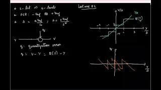
and then you can encode them using binary bins right if you have n Bits you know you can have two power n you know possible levels and you can do it so let's quickly look at the characteristics of quantizer so let's say the input is y the output is V and the mnemonic you see the quantizer is basically rounding off right it is basically you know making some error so you can think of the input y when it's rounding off when it's getting rounded off its tail gets chopped off we get weak to remember right
so great so now let's say again the input is ranging from minus V ref to say a plus v ref let's say I want a total of eight levels that is I want to divide the range of input amplitudes into total of eight levels so basically one two three four in the negative axis again four right oops sorry it's disappearing pin so what do you think is the width of this huh no it's not a two V ref divided into eight right so often this is called the step size or Delta so in this case
it is the range which is 2 0 by 8 and if you have total of L levels 2 V ref by total number of levels it's all right so again for Simplicity what I'll do I'll scale this by Delta I'll say it's 1 Delta 2 Delta 3 Delta 4 Delta so similarly it's minus 1 minus 2. is 4. right input yes so again we are going to round off so any uh signal any amplitude in this range 0 to 1 Delta what will I round it off to huh a Delta by 2 so 0.5 so
let's say I round it off to point five which is say here similarly in the negative side 0 to minus 1 and round it off to minus half fine and then I'll do that for all applicants right so great so yeah one more uh jargon so this entire range of minus V ref to plus v ref that's called the full scale range okay yeah and now we have eight levels so we can encode them using how many bits eight levels three bits right so we can just say zero zero zero zero zero one and so
on right blah blah blah and this this step size Delta is also called as LSB size simply because if you want to change the LSB by one bit at the most I have to change the input amplitude by one Delta right right and uh yeah so it turns out this is not the only way in which you can have the quantizer characteristic see here if you look at it the zero or the middle of the full scale range kind of lies in this transition point right but I can also choose the characteristics in such a
way that the zero lies in the flat region that is also another possibility so this kind of quantizer characteristic which has a rise in the middle of the characteristic is called mid-rise so we'll have the other thing which is called mid thread wherein you make sure that around 0 it's constant so here we'll say from say minus Delta by 2 to plus Delta by 2 0 and then you sort of keep doing it sorry this correct yeah so I mean there are a couple of differences not significant so Oneness you see that if your input
amplitude is close to zero right it's very close to zero what will be the output here it will be zero and if the input if the input is again very close to zero what will be the output here I mean let's say it's uh small right around zero it's varying by a small amount what will happen in a sort of toggle between you know the yeah so I mean if you want to have a you know clean output for low signals you might probably want to do this else is better another thing is see here
if you want to have uh in this mid trade quantizer if we have a symmetric characteristics I should have a odd number of levels right here see I have three four five six seven because zero is one of the levels I should have uh you know same number of levels on positive or negative so we'll have total of odd whereas here I can get a symmetric thing with a even number of levels minor difference okay and uh unlike sampling and before by the way uh we looked at sampling rights the sampling a linear operation or
a non-linear operation when is an operation on sorry okay business operation linear I mean let's say see if what is the condition for linearity and something else right for zero input I should have zero output homogeneity and if I scale the input output should also scale if I have a zero input when I sample it is output to zero zero if I have some input and scale that input after sampling with the sample load would also scale so it's linear or non-linear it's a linear sorry sampling is not like I mean sampling is linear but
the thing is it is not time variant no no sampling doesn't involve contribution sampling doesn't equals it converts in the frequency domain but we are looking at the operations are all in time domain right so sampling is a linear operation huh sampling alone this sampling is linear right but of course quantization is not linear like what is pointing out right you can see if I have some input I get this output I scale the input to sum this value the output doesn't change and obviously because of all these jumps it's non-linear right so it's very
difficult to analyze so uh in the next class we'll see how we go about analyzing or understanding quantization so let's stop here I didn't record