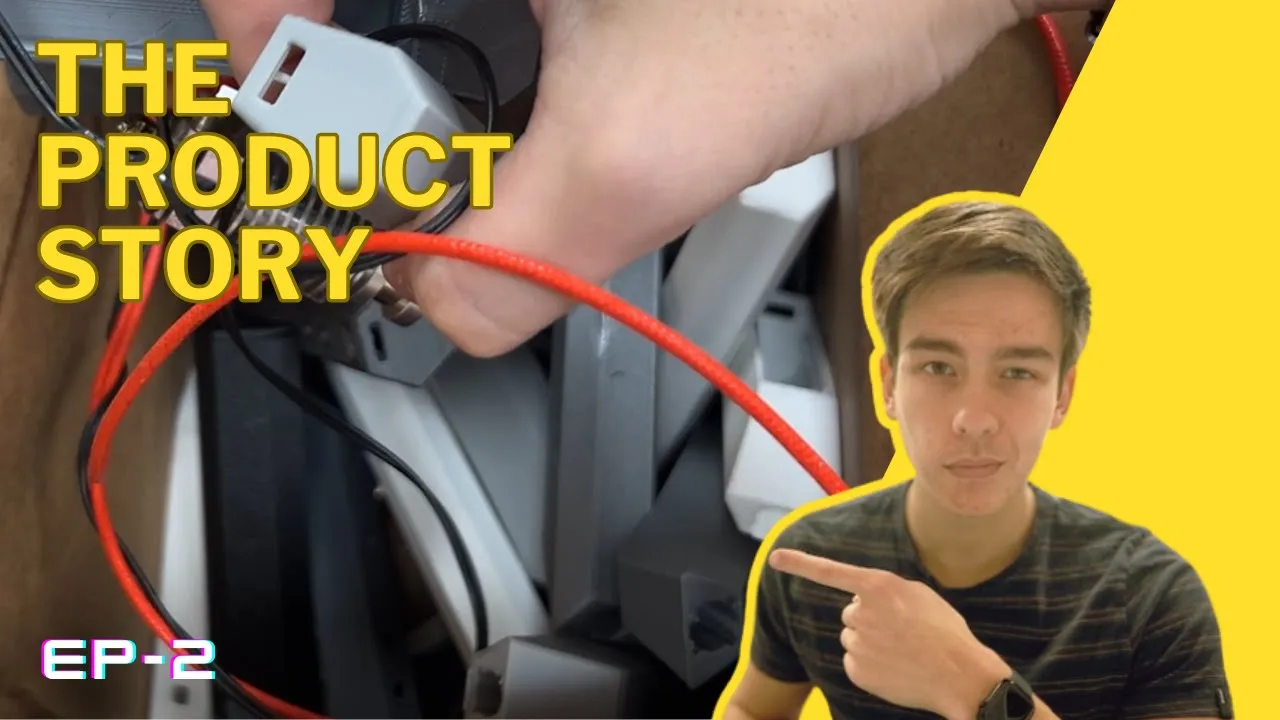
Hey everyone. If you haven't seen episode one of the series, I highly recommend it since we go over why we're doing all this in the first place and lay out our design guidelines. But if you've forgotten, this series is about designing and launching my first product that helps treat TMJ disorder.
And I'll take you on my journey from ideas to designs to prototypes to production to branding and to sales. For this episode, I want to jump right into component selection. I find this to be the best thing to start with because it'll help us with initial dimensioning and form factor design, as well as figuring out our total current draw, which is crucial for dialing in the electronics.
So, last episode we discovered that the best at home treatment for TMJ disorder is heat and massage. So, might as well start with the massaging part. A while back, I was considering creating a percussive action like the guns or potentially play around with resonance and give the tip some throw.
But as I've stated before, we're trying to make an MVP here. Sometimes it's hard to choose what features to drop, but in this case, I chose to go with a simple vibration motor. At the front of the device, we need a tip that will transfer heat to the jaw as well as allow for some high pressure massaging.
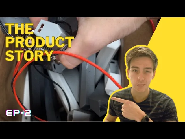
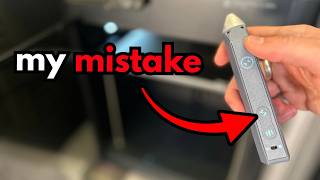
We'll also of course need a battery as well as a circuit board that contains all the necessary features like USBC charging, a microcontroller, voltage regulators, connectors, buttons, and indicator LEDs. For the user interface, I settled on the simplest solution to have two buttons, each cycling through heat and vibration power, respectively. The indicator LEDs will be for displaying those power levels along with some battery charging states.
I'm thinking that we can wrap these LEDs around the buttons and kind of make a power level ring instead of having them all lined up, which will save a ton of space. For turning it on and off, I'm struggling to pick between a button and a switch. A button would obviously feel and look so much better, but adding the extra circuitry to make it a soft latch and worrying about drainage and accidental triggers is definitely adding some complexity compared to the simple switch.
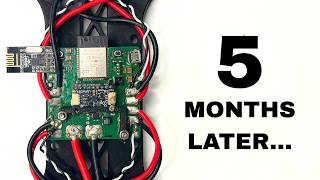
I think this is another improvement that we'll have to leave for the V2. Now, onto the heating element. My first thought was to look at a copper coil that can fit around or inside the massaging tip since I couldn't imagine squeezing a pad into a tip.
But then I remembered that 3D printers use these tiny ceramic cartridge heaters which are the perfect size and shape I'm looking for. So I took apart an old extrusion head and wired it up to test. Looks like it gets plenty of hot at fairly low voltages and only draws around 350 milliamps.
Obviously, we won't know how much heat we'll actually need till we design the tip cuz heat transfer, but I think this will work. The specific vibration motor I found in Digi Key, and I picked it because it had the most vibration force and can run at the highest voltage. It's better to do something overpowered that fits and then scale down later if it's too powerful, then go the other way around.
It also says it draws around 150 milliamps. So, now we can pick out the battery. Looks like when we take into account the boosting from 3.
7 volts to operating voltage, we end up having a maximum current draw of around an amp. So assuming the user on average uses 20% less power than the maximum, we can use these 800 mAh 14500 lithium ion cells that are the perfect size and get us an hour of run time. With everything picked out, let's figure out what we want this thing to actually look like.
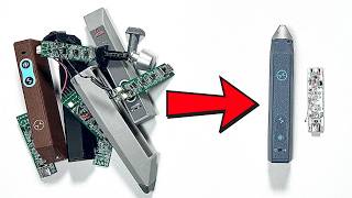
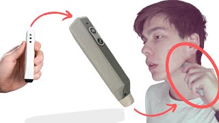
It's definitely going to be some sort of high aspect ratio tube thing since all of our internal components are pretty cylindrical. We're trying to avoid any phallic imagery here. So, the farther away from an organic form, the better.
So, between that and making sure the device comes out of 3D printers, well, I'm really leaning towards some sort of hexagonal tube. As you can see, I'm imagining a finger grip like this. And a hexagonal profile fits really nicely within it.
and on a 3D printer, it won't need any support material. This was one of the first look-like prototypes I printed out. My idea for the tip was to have a large surface area for heat transfer while having a nub that presses deeper into the skin for some added pressure.
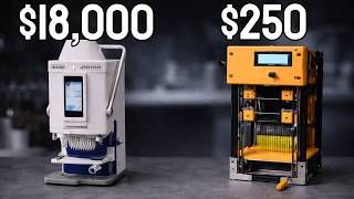
I of course tried to see if there was any chance for plastic to be a viable mode for heat transfer, but just ended up with some melted plastic instead. It's probably doable if we were injection molding, but I don't have the money for that right now, which is why the obvious solution was machining the tip out of aluminum. While testing out the initial design, I noticed that I actually really preferred the end of the slant for massaging more than the nub.
And I figured if I round out the corners a little and make the switch to aluminum, there will still be enough area to deliver heat. I did a quick little redesign and played around with how it felt on my jaw until I got something worth sending out to the manufacturer. Fast forward a bit and boom, here it is.
As always, pretty much as soon as I sent the part out, I found ways to redesign it, but it's still nice to be able to verify the heat transfer is good around 5 volts and get some first uses in. But yeah, I really didn't think through how I would keep the tip constrained. I intended to use a screw to constrain it, but quickly realized that was overkill.
I then designed a snap fit feature for the holes instead, but couldn't get rid of the play. And after talking to the manufacturer, I realized they turned the tube end. So, I added a groove and chamfer to make the snap fit way nicer.
To prevent rotation, I wanted to add some kind of key feature, but ended up costing way too much. Instead, I made the cutout on the head of the tip, which got my quote down 50 to 70 cents per unit. It worked perfectly 3D printed, so I sent out another sample request, and it should arrive when we're farther along with this project.
Back to the casing, I realized I was going to need a little more height for the battery and PCB. So, instead of a normal hexagon, I'm going to squish its sides in and make it taller. This fits even more nicely in your hand because there's a lot more space for the thumb to sit on and there's a bit less presence in the grip.
I later noticed what I had just looked too rectangular from the side. I really like this leaf shape I've seen around, so I decided to add those diagonal fillets to slim out the side profile. On the inside, we've got a few things we need to do.
I added these extrusions to act like snap fit receptacles for the battery and PCB. So, the battery just snaps in there and the PCB goes right on top. Then we have the motor locator, which you can snap the motor into, but tightening it down is super important because we don't want any rattling or loud vibrations.
I want to minimize part count, so I decided to be super cheeky here and use a zip tie to hold the motor in tight. I like it cuz it requires no extra printed components, won't loosen from vibrations, and really makes use of 3D printing with that embedded channel. In the same mindset of reducing parts, I've been slowly getting rid of screws in these casing designs.
Now, I'm even playing around with using no screws. Every design I tried though ended up having some sort of play or gap, which feels cheap. But I really like the idea of having no screws showing.
So, I'm just going to keep iterating on different snap fit and retaining features. Right now, the one that's working best is having extrusions on the side that snap into its inverse in the casing. They've got a taper on the end that guides the cap between the casing walls.
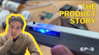
The cover has a few other features worth noting. As I mentioned, I wanted to have the LEDs make a sort of ring around the buttons. I wasn't exactly sure what the neatest way to display them was, though.
I didn't want to have any holes, nor did I want to use a sticker or insert any light pipes or different materials into the print. But I realized that if I use a light colored filament and made the layer height over the LEDs super thin, I could have the indicators be totally invisible on the surface. That is until you turn on the light.
And then I added blinder walls around the LEDs so they don't interfere with each other. The other feature I've been playing around with is this guide for the heating element wires because they pass right over the motor and I don't want them drooping down and getting caught. But currently, I'm having some trouble consolidating this with the fact that I plan on pressing the cap in on the other side, meaning the wire is going to have to be longer than it needs to be, so it can be pre-outed through the guide, which makes the assembly annoying and waste precious space.
And the design for assembly is really important here. With this dense and thin of a part, it's important that every component can be placed with ease. So, I think I'm going to have to try to move the wire guide onto the case instead of the cover.
Other than wire management, another thing that makes design for assembly tough here is that the walls of the casing converge, making the opening smaller than most of the components inside. So, I'm banking on the plastic bending out and having guiding features to slide the parts in without too much fuss. But designing the walls to be bent out comes with the consequence that unless everything fits perfectly inside, they get pushed out and result in gaps of the cover.
This is almost antithetical to the fact that the component fits inside needs to be extra tight to avoid any rattling. You might be wondering, how am I even making all these tweaks without having the PCB designed? Aren't all those electronic components probably going to change everything?
Well, I'm not. I'm actually kind of cheating since at the time of making this video, I had a preliminary version of the circuit board made. So, next episode will be all about catching up in the electronics department.
a bit of programming and hopefully some design updates on this pesky case. See you.