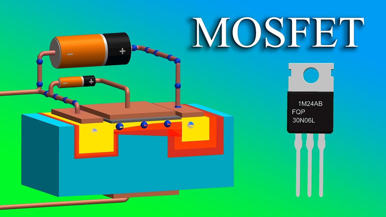
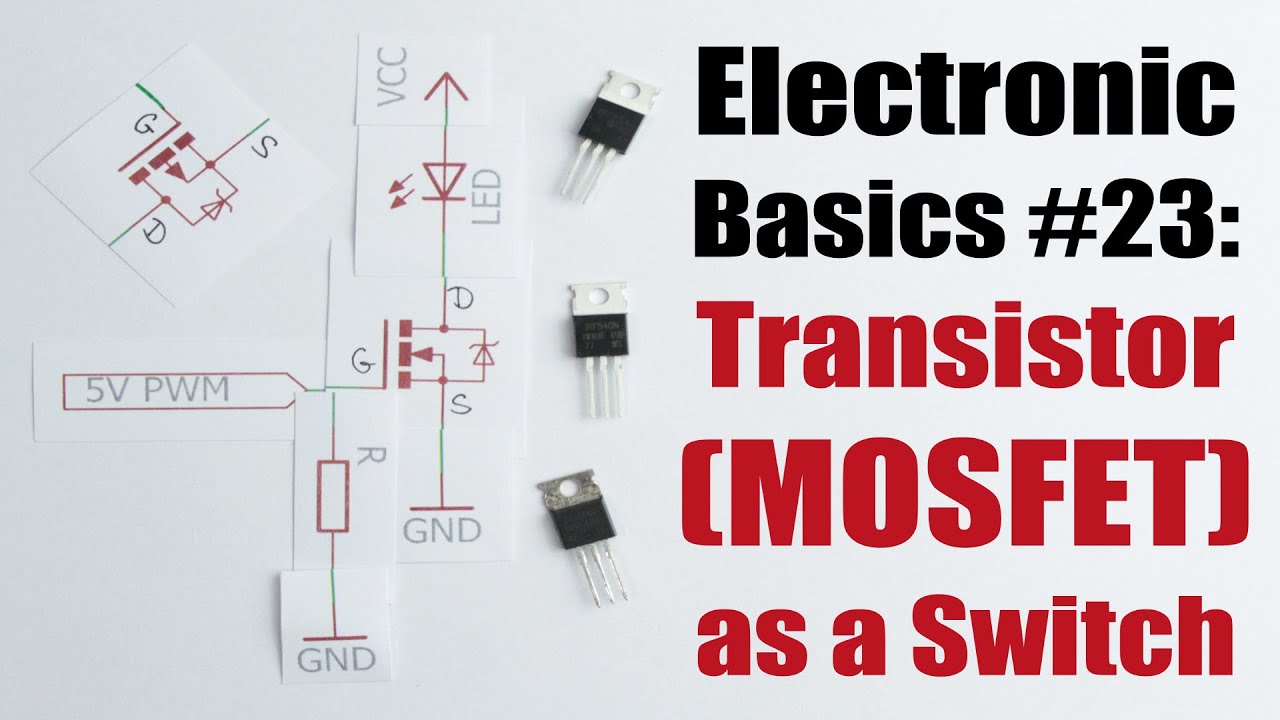
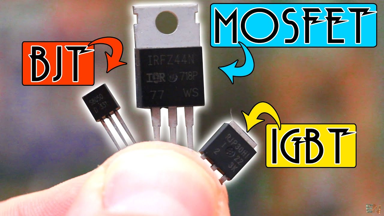
Hey friends welcome to the YouTube channel ALL ABOUT ELECTRONICS. So in this video, we will learn how the MOSFET can be used as a switch. Now the BJT can also be used as a switch.
But the MOSFET has certain advantages over the BJT. So as you are aware this MOSFET is the voltage control device. That means just by controlling the gate to source voltage, this MOSFET can be turned on or off.
And in this way, it can be used as a switch. On the other end, this BJT is the current control device. That means by controlling the base current this BJT can be driven either into the saturation or the cutoff region.
And in this way, it can be used as a switch. Now at the low drive currents, the required base current for driving the BJT in the saturation will be lower. So for the low driving current applications like for driving the Leds this BJT is very cost effective solution.
But when this drive current is in ampere, then the required base current to drive the BJT into the saturation will also increase. And in that case this control circuit or the driver circuit which provides the required base current should be able to provide the enough current to drive this BJT into the hard saturation. So if you want to control the BJT as a switch using the microcontroller or any logic circuit, then it is not possible for the very large current.
On the other end, if you see this MOSFET then it is the voltage control device. So just by ensuring the constant voltage between this gate and the source terminal, it can be easily used as a switch. And if the MOSFET is a logic level MOSFET, then it can be easily controlled even using the microcontroller.
But in case of the continuous switching and particularly at a high frequency switching we also need to consider the other aspects of the gate driving. But we will talk about it little later. But the thing is the MOSFET is easy to drive compared to BJT.
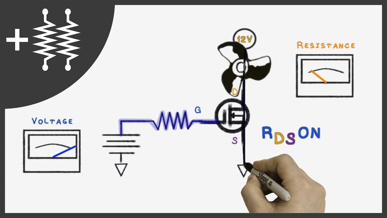
The second thing is for the continuous switching applications, these MOSFETS are more power efficient than the BJT. So when the MOSFET is in on condition, then it acts like a resistor. And in the on condition the drain to source resistance will be very low.
So for high power MOSFETS, it is typically in the milli ohms. So even at very high currents, if we see the conduction loss in the MOSFET, then it is comparable or slightly higher than the BJT. Now when the BJT and the MOSFET are used as a switch, then there are two types of losses.
One is the conduction loss and the second is switching loss. So the loss which you have just discussed is the conduction loss. That means whenever the switch is in the on condition, then the loss across the switch is the conduction loss.
Now when the MOSFET and the BJT is used in the continuous switching application, then the switching loss is very crucial factor. And for the MOSFET this switching loss is lower compared to the BJT. So at high frequencies in the continuous switching applications this MOSFET is more preferred over the BJTs.
Moreover the MOSFETs are more thermally stable compared to BJTs. The reason is the MOSFET has the positive temperature coefficient. That means during the on condition or in the on state as the temperature of the MOSFET increases, then the on resistance will also increase.
And because of the increase in the on resistance the drain current id will reduce and because of that the temperature of the MOSFET will reduce. On the other end the BJTs have the negative temperature coefficient. That means as the temperature increases, then this character current IC will also increase.
And the increase in the collector current will further increase the temperature. So if the generated heat is not dissipated properly, then it may lead the BJT into the thermal runaway. That means MOSFETs are more thermally stable compared to BJT.
So in short the MOSFETs are easy to drive than the BJT and can work more efficiently at the high switching frequencies. Now as we have seen in the earlier videos, there are two types of MOSFETs. The depletion type and the enhancement type.
But typically the enhancement type MOSFETs are used as a switch. So for the depletion type of MOSFET these are the transfer characteristics of the P channel and the N channel MOSFET. And as you can see, they are normally on devices.
That means by default when the voltage VGS is equal to 0, or when the control input at the gate is 0 at that time the current is flowing through the MOSFET. So when the control input is 0, at that time these depletion type MOSFETs are in the on condition. And when the control input is greater than the pinch of voltage, at that time only they are in the off condition.
So because of this characteristic, they are not preferred as the switch. On the other end the e MOSFETs or the enhancement type of MOSFETs starts conducting, when the voltage VGS is greater than the threshold voltage. So if the input is less than the threshold voltage, then it will remain in the off condition.
So these e-type MOSFETs are normally off devices, and this characteristic is more preferable for using them as a switch. Now this is the drain characteristic of the enhancement type of MOSFET. And when it is used as a switch, then it is operated either in the linear or the ohmic region, and the cut-off region.
So in the cut-off region when the control input VGS is less than the threshold voltage, then the drain current ID is almost 0. And in the on condition, when it is used in the linear region then the MOSFET acts like a resistor. And the slope of this curve is the RDS(ON).
So this RDS(ON) is the resistance of the MOSFET in the on condition. For example for VGS is equal to 5v, if these are the operating voltage and the current, then the ratio of this voltage and the current will give us the RDS(ON). And as you can see as the voltage VGS increases, then this RDS(ON) will reduce.
So this RDS(ON) is one of the important parameter for the MOSFET. And the value of this RDS(ON) should be as low as possible. Because as I said earlier, in the on condition of the MOSFET the conduction loss of the MOSFET depends on this ON resistance.
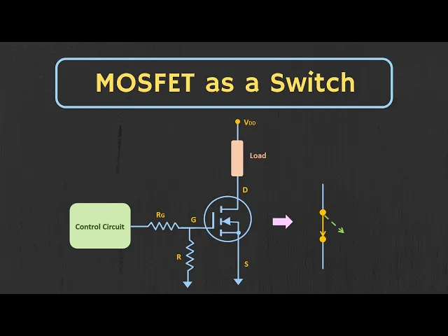
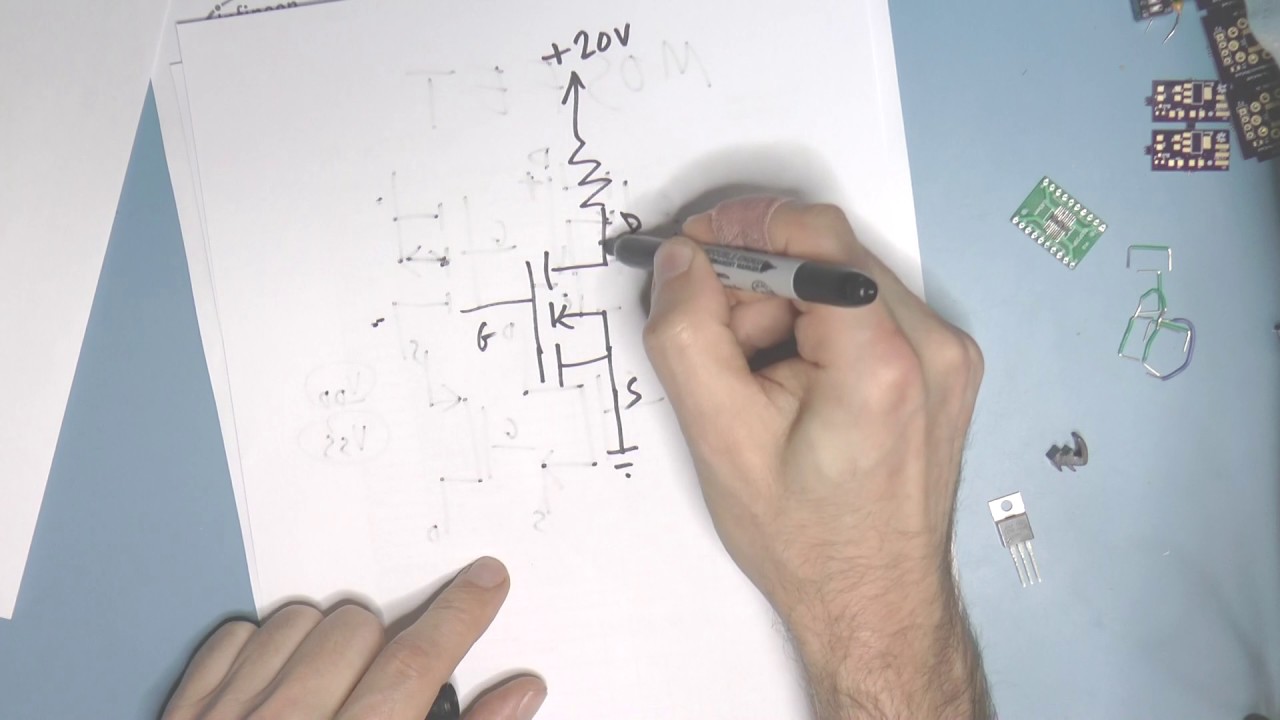
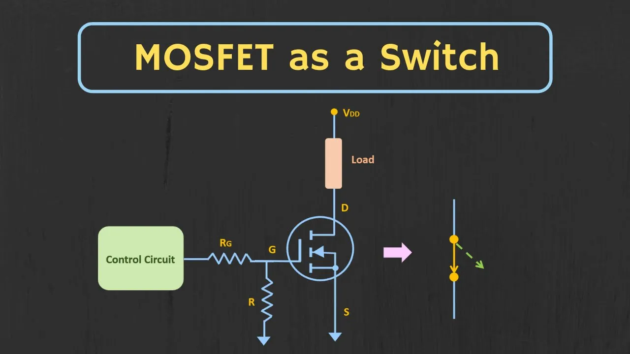
So this is the basic circuit of the n-type MOSFET which can be used as a switch. So as you can see here, the load is connected between the supply and the drain terminal, and the control input is applied between the gate and the source terminal. So this control signal can be applied directly through the microcontroller, or it can be applied using the separate driver circuit.
Now when this control input is low, then the MOSFET will act as a open circuit. And in this case no current will flow through the load. Now whenever this control input is more than the threshold voltage, then the MOSFET will act as a closed switch, and the current starts flowing through the load.
So whenever the threshold voltage of the MOSFET is less than 2 to 3 volt at that time this type of MOSFETs can also be operated using the microcontrollers. Now as I said, when the MOSFET is in the on condition, then it should operate in the linear region. That means for the given load, by properly selecting the supply voltage, we can ensure that it operates in the linear region.
For example let's say this RD is the load resistance. And in the worst case assuming this VDS is equal to 0, the maximum current through the load will be equal to VDD divided by RD. And whenever the switch is in the open condition, or whenever this drain current id is equal to 0, at that time this voltage VDS is equal to VDD.
So for these two extreme cases we will get the two points. And by joining these two points, we can get the load line. So the intersection of the load line with any of these two curve, will give us the operating point.
So let's say if we are operating the MOSFET at VGS is equal to 5 volt, then this intersection point should fall in a such a way that the MOSFET operates in the linear region. Or at least that is how we should select the load line. Now if you see the data sheet of any MOSFET then the some important parameters and the important curves are already given in the datasheet.
For example for the MOSFET 2 and 7 triple zero g the threshold voltage is between 0. 8 and 3 volt. That means it can be operated using the microcontroller.
And here for the typical value of the VGS, we have been also given the value of the RDS(ON). Now for this particular MOSFET the maximum continuous drive current is equal to 200 milli ampere. That means in the worst case condition the current which is flowing through the MOSFET should be less than this value.
So let's say using this MOSFET, we want to drive the 30 ohm load. And in the on condition the current through the load should be around 150 milliampere. That means whenever the VGS is equal to 5 volt, then the current through the load should be around 150 milliampere.
And with VDD is equal to 5v, it is possible to do that. So with VDD is equal to 5v, and RD is equal to 30 ohm this will be the load line. That means whenever the VDS is equal to 0, at that time this strength current ID is equal to 5 volt divided by 30 ohm.
That is around 166 milli ampere. And whenever this ID is equal to 0, then this VDS is equal to 5 volt. That means this will be the load line.
And the intersection of the load line with the VGS is equal to 5 volt curve will gives us the operating point. So in this case if you see the MOSFET is operating in the linear region. And the drive current is typically around 150 milliampere.
So in this way using the datasheet of the MOSFET for the given drive current, we can select the supply voltage as well as the other components. Now so far in our discussion we have directly applied the control voltage to the gate terminal. But actually there should be some series resistor between the gate and the control input.
So let's understand why? Now so far we understood that the gate of the MOSFET offers a very high input resistance at the low frequencies. That means the gate terminal hardly draws any current from the supply.
Right? But to turn on this MOSFET when we apply the input through this control circuit without this series resistor, then without this series resistor the MOSFET can draw a lot of current during the transient. And if this control circuit is not able to supply that much of search current, then it can damage the control circuit.
Because if we see the gate to source terminal of the MOSFET, then in the equivalent circuit it will act like a capacitor. So when we apply the input voltage through this control circuit or through this microcontroller pin, then this capacitor suddenly tries to charge to the input voltage. And during this transient it can draw a lot of current.
But if we connect this series resistor, then this series resistor restricts the transient current. For example if the MOSFET is controlled using the microcontroller pin, and the maximum current which is supplied by the microcontroller is 20 milli ampere at 5 volt, then the value of the resistor should be at least equal to 250 ohm. So this will ensure that the maximum current which is being drawn from the microcontroller pin is less than 20 milli ampere.
Apart from the series resistor, the pull down resistor is also required at the gate terminal. So during the power up of this control circuit, this pull down resistor ensures that the MOSFET remains in the default condition. That means whenever the input is 0, then the MOSFET should remain in the off condition.
Now so far in our discussion, we have talked about the n-type MOSFET. Similarly let's talk about the p-type MOSFET. And let's see how it can be used as a switch.
So as you can see, the transfer characteristic of the p-type MOSFET is exactly opposite to the n-type MOSFET. That means to turn on this p-type MOSFET, the voltage VGS should be negative. So if we want to use the same control circuit or the same microcontroller inputs for this p-channel MOSFET, then this is how we can connect the load to the p-channel MOSFET.
So as you can see here the source is connected to the VDD, and the load is connected between the drain and the ground terminal. And using the pull up resistor the gate is connected to the VDD. So this pull up resistor ensures that, the voltage at the gate remains at the default 5 volt, when the microcontroller or the control circuit is getting powered up.
So when the control input is high, at that time the voltage VG and the VS both are at the same potential. That means in this case this VGS is equal to 0. So because of the VGS is equal to 0, the MOSFET will remain in the off condition.
Now when this microcontroller output goes low, then this voltage VGS will become negative. And because of that the MOSFET will get turned on. And due to that current starts flowing through this load.
So this is how we can also use the p-channel MOSFET as a switch. Now so far we understood that the MOSFET can be turned on or off using the microcontroller. But this type of switching is the slow switching, meaning that once the microcontroller pin goes to the high or low state, then the MOSFET will take some time to completely gets in the on or off condition.
So if you want to use the MOSFET for the continuous switching application, and that too at the high frequency, then we also need to look for the other parameters in the datasheet. So this total gate charge is the amount of charge which needs to be injected into the gate terminal to completely turn on the MOSFET. And from the total gate charge we can estimate how fast the MOSFET can be switched on or off using the given control circuit.
So as you are aware this charge Q can be given as I times T. Right? So let's say for a sum MOSFET if this gate charge is equal to 20 nano coulomb and the maximum current supplied by the driving circuit is equal to 20 milli ampere, then the time required to turn on this MOSFET is equal to 20 nano coulomb divided by 20 milli ampere.
That is equal to 1 micro second so for this type of MOSFET if we try to drive the MOSFET using the microcontroller, then this is the typical time it will take to turn on. And if the value of the total gate charge is more, then it will take more time to turn on. On the other end, if the gate driving circuit can provide a maximum current up to 1 ampere, then the time to turn on the MOSFET will get reduced to 20 nanosecond.
And in this case it is possible to use the MOSFET for the fast switching applications. That means for the fast switching applications, this total gate charge should be as low as possible. And the MOSFET should be driven using the gate driver IC such that it provides a sufficient current for the switching.
The other advantage of this fast switching is that the switching loss in the MOSFET will reduce. So as I mentioned earlier, for the continuous switching application, this switching loss is very crucial parameter. So when the MOSFET is in the off condition, then the voltage VDS is equal to VDD.
And the drain current ID is approximately equal to 0. So the power loss across the MOSFET is approximately equal to 0. Now when the MOSFET goes into the on state, then this drain current starts increasing.
And as soon as it reaches the on condition current, then the voltage VDS starts reducing. So during the switching phase both drain current ID and the VD are on for some time. And this triangular wave shows the switching loss during the on time.
Now when the MOSFET is in the fully on condition, then the power loss across the MOSFET is the conduction loss. And once again when the MOSFET goes into the off state, then the voltage VDS starts increasing. And as soon as it reaches to the VDD, then the drain current ID starts decreasing.
So once again when the MOSFET is getting turned off, then we are also getting the switching loss. So the area under the curve of this two triangle is the switching loss. And with the faster switching the area under these two curves can be reduced.
And because of that we can also reduce the switching loss. So this total gate charge is very important parameter for the MOSFET in case of the continuous switching application. So I hope in this video, you understood how the MOSFET can be used as a switch.
And what are the factors we need to look into the datasheet to use this MOSFET as a switch for the specific application. So if you have any question or suggestion, then do let me know here in the comment section below. If you like this video hit the like button and subscribe the channel for more such videos.