Hi ,Welcome to module 36. In this module we are going to look at the GCD problem and how, what this data path is and what a controller is. So, let us look at this picture that we ended up in the last lecture with.
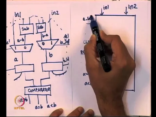
So, we have all these basic circuit elements, so I am going to make one small change. So, I am going to call these select lines, because these are actually select lines for the multiplexer and since this is a register. So, what would happen is, so any time there is clock that is coming into any of these, if it is a plain register, then this register will always take the value that is coming out of the mux and give it to the comparator, it will also give them to the subtractor and so on.
So, remember there is a link that is going from here to both the subtractors. So, from a it goes to two subtractors, from b it goes to two subtractors and it is also going to the comparator. So, what I want is, I do not want this to happen all the time, so I am going to place some control on the registers on when they get loaded.
So, what I want is, when a load equals 1, the output of this a register will follow the output of the mux. If a load is equal to 0, then it will keep the old value as it is the same thing with b So, I want to use this underscore load for that signal and select for the multiplexer select. So, with that small modification let us see what a data path is.
So, data path as the name indicates is the path through which the data is moving around. So, path is a sequence of steps, so data path essentially means what is the path through which data is moving around. So, let us just imagine these two numbers, let us say I took this example, a was equal to 42 and b was equal to 16.
So, let us say that these are the two numbers that are initially given, a is 42 and b is 16, once 42 and 16 are presented as the input, then 42 and 16 should appear at, will appear at the 1 input of these 2 multiplexers. Then, some of magically this a select and b select should both be one, so that gets into these lines a and b and once that happens, somehow a load and b load should both be one. So, that the values from the external world is actually registered on a and registered on b So, this should happen first, somehow this a select, b select, a load and b load should all work together, so that the value from in 1 is copied to this and in 2 is copied to this But, you can see how the data is passing through.
So, it is coming from this line here through the mux into this register, it gets register there, the value a starts from here, goes through the multiplexer and gets registered here Once that happens, then this a will appear as the subtractors input in these two places, b will appear at both the subtractors inputs and a and b will also appears at the comparators input Since, subtractors and comparator are combinational circuits, any change in input will go and change the output. So, these results a greater than b, a equals b, a less than b will come out of some point of time Similarly, when you supply two numbers, a minus b and b minus a these two results will come out at some point of time and at an. .
. So, once that happens, then we need to appropriately select one of these things, either a select should So, a select should first of all go to 0, so that it can start taking from the subtractor, b select should also take it from the subtractor, so it should also go to 0. It will remain at 1, only when you want to take the external input, it should go to 0.
And once that happens, the subtractors output will appear here and here. But, remember according to the algorithm, only one of the value changes, either a gets a minus b or b gets b minus a, only one of them should change, which means either a load or b load should be 1, both of them cannot be 1. So, somehow we need some circuitry to do that, but if you look at it as, how the data is moving through a and b start from here, let us say 42 and 16.
We go through the multiplexer, they get registered here, they get compared, then 42 appears here, 16 appears here and similarly 16 appears here, 42 appears here and 42 minus 16, 26 will appear here and 16 minus 42 minus 26 should appear here. And if a select is 0, 26 will come here and minus 26 will come here, we want 26 to be copied, but b should not be destroyed. So, we do not want minus 26 here, so if we copy 26 here, this 42 becomes 26, but 16 remains as it is.
If we keep b load equals to 0, 16 will remain as it is, then we will have 26 and 16. Then, 26 would come here, 16 would appear here, 26 minus 16, 10 will come here, this will have minus 10. So, you will have 10 and minus 10 here, we want 10 to be registered in this register, we do not want minus 10, instead it should retain the old 16 itself.
So, you will have 10 and 16. So, once 10 comes here and 16 comes here, 10 minus 16 minus 6 will come here plus 6 will come here. We do not want minus 6 to be registered, it should keep the old value 10, but 6 will come here So, then you will have 10 and 6 and so on.
So, what we are seeing is, the data flowing from, you can think of it as data flowing from the output of this register going through some combinational logic, coming back to the register itself, under some appropriate conditions, you either change the register or you keep the register as it is. So, this is the notion of what is called a datapath. So, I am going to draw a block diagram kind of a set up for the datapath.
So, what I am going to do is, I am going to think of it as a circuit. So, let us forget the internals for a while, so I am going to only draw the block diagram, in this block diagram, let us see what are all the different things that we need. So, first of all I need input 1 and input 2, these are external inputs.
So, I need input 1 and input 2, then I always have a clock that is going to come in, because this is the sequential circuit. So, let me remove this picture, so I will keep it on this side, we will use it later. So, we will need a clock and we will need a reset signal, so these two for any sequential circuit it is always good to have a reset signal also and we have a clock.
So, besides these things, there are a few other things that are required. So, if you go and look at this picture here, there are 3 inputs a greater than b, a. .
. So, there are 3 outputs a greater than b, a equal to b and a less than b, these are 3 outputs. So, somehow there is, so we have to design another piece of circuitry which will take these three and tell each of these multiplexers and loads, what they should be assigned to.
So, in some sense what we need is a marching instructor. So, what we have is the hardware required for, how the data is supposed to flow through. So, it takes care of all the different paths through which data can flow from one register to the other and so on.
So, what we have is the data flow, what we do not have is the control, so control is like the marching past instructor. So, this instructor is supposed to take these inputs and supposed to tell the data path here, on what these values are, so that the data can flow through. So, in some sense what we need is, we need 3 output signals and these 3 output signals can only come from the datapath, because data path is the one which is having the comparator.
So, the comparator inside is going to give 3 outputs, we are going to tap it to the external world So, I am going to have this as a greater than b, a equals to b and a less than b, so these are outputs to the external world. So, from the comparator they need to go on, then again let us look at the circuit. We have this select and load lines for a and b should come from the external world, these when I say external world, we will have to think about where it is going to come from.
So, that is going to come from a circuit that is called the controller. So, let us assume that this a select, b select, a load and b load are going to come from the instructor which says, what these values are supposed to be. So, we have pretty much everything except for one small thing, so earlier when I showed a comparator.
So, there is a comparator that is giving 3 outputs and finally, I said in the algorithm we also need the output, I put a print a. So, what I am going to do is, I am going to tap a and give it to a register. So, I am going to call this the output register, this output register will not always have the correct output.
So, what I am going to do is, I am going to take a signal from the external world, I will call this output enable, then output enable is 1, it will copy a and give it to the external world. If output enable is 0, whatever value was there in the output register, it is going to keep it as it is. So, essentially there is one more input called output enable, so let us say I put it here output enable and there is one output, it is going to come out.
So, if you think of it like an algorithm, all you will have is basically just the black box this. This is the black box you will think about. If I tell you an algorithm for GCD, it is supposed to take two inputs and it is supposed to give an output that is it, that is all you will think about.
But, when we think it in terms of hardware design, we cannot leave it as a black box like this. Because, this is supposed to do something in steps we have a clock and reset and this circuit cannot operate by itself, we need to have something slightly more complicated, because we need to drive various signals and so on. So, I am going to call this my data path and let us see the signals that is coming in.
So, there are several signals that are coming in, there is clock, reset and several things that are going out and so on. Now, one thing I am going to do is, I am going to draw different circuit called the control path So, this control path is going to be a slightly tricky business, so somehow it should take the inputs that are coming in from data path. So, it should take the outputs of datapath, read them there and somehow, find out at what point it should do what, so that is the meaning of control.
So, control the word says, it should somehow be able to give marching instructions for the data, so that it can go through the right location and so on. So, what this is supposed to do is, it suppose to be first of all driving all these lines. So, a select, b select, a load, b load and output enable should all come from what we are going to call the controller.
The controller cannot make these decisions independently. So, remember once a equals to b, then the controller is supposed to tell the data path do not do any more subtractions, whatever values in a, it is supposed to be coming to the output. So, it is not going to do something independent of the datapath.
So, it is going to take these three input signals a greater than b, a equal to b and a less than b and now, you can see that there are two things that are going to work in tantrum. So, the data path is going to tell the controller, this is the current status of the subtraction and whether, one is greater than the other, equal to the other or less than the other. And the controller will in turn indicate to the datapath, whether it should be doing more operations.
So, you can think of it as, controller gives some kind of instruction to the datapath, not explicit instruction through the signals, it is going to tell the data path to do something. The data path does the computation and in turn it gives the results back to the controller, the controller is supposed to process the inputs and supposed to tell the datapath, what to do next and so on. You can imagine this thing happening in a loop like fashion.
So, the controller will tell the data path something, the data path will in turn do the results, controller will look at the results and gives, sends something back to the data path as control signals and so on. So, we are going to call these signals a select, b select, a load, b load and output enable, these are called control signals. Because, they are controlling how the data is flowing inside the datapath.
Clock and reset are actually signals to the external world and the controller is also supposed to take a clock and reset. So, there is also the same input clock and reset that is supposed to come to the controller and this in some sense tells you, what is the controller and what is the datapath? So, the only thing that we do not have so far is, what is the overall thing that is going to look like.
So, I am going to draw this in the next picture. So, the overall design I am going to have is something like this. So, I am going to design the overall chip, this is going to be my GCD controller, my GCD machine, let me call it the GCD machine instead of controller.
So, I am going to call this the GCD machine. So, what the GCD machine is going to do is, it is going to take clock as input, because for any sequential circuit you will need that. It will take reset as input, it will take inputs called IN 1 and IN 2 from the external world and it is going to give output.
But, it is going to do some few more things. For example, how do we know that the IN 1 and IN 2 are actually present and so on. So, what we are going to do is, we are going to take one more input called GO.
What this GO is going to do is, we will first place the input IN 1 and IN 2 and once it is stable, we will tell this chip to say GO and now compute this. So, that is what this GO, the input bit go is supposed to be. If GO equals 1, then this chip is supposed to take the inputs IN 1 and IN 2, process whatever it is supposed to do and give the output.
The other thing that we need is, whenever the output is ready I need some indicator from the chip that, the result is ready. So, for that I am going to have an output that is going to be called DONE. So, this done signal whenever done equals to 1, then the output is correct, till then I am not supposed to inspect the output, I have to wait till done equal to 1 to inspect the output.
So, let we see the whole thing in mind, so let us see what this whole thing is supposed to be So, there is a clock and reset which are both implicit, so I am going to assume that the chip is going to take that anyway. So, we have 3 input lines, input 1, input 2 and GO. So, whenever we design a chip, it usually it has to some kind of agreement.
The agreement we have the external world is, the external world will first of all put the data inputs at IN 1 and IN 2 and then give the signal called GO. Once the GO is given, the circuit is going to take a few cycles, whatever number of cycles to produce the output. When the chip is processing, it will keep done equals 0, if the chip actually currently processing something done will be equal to 0.
At some point, the chip is supposed to raise the input done equal to 1, at that point I can go and inspect the output. But, when done equal to 0, it means that chip is still processing, I cannot go and give q inputs by raising go again. So, what I want is, I want some kind of understanding between the chip that I am designing and the external world.
External world has to follow some constrains, that once it is given a set of inputs to be processed, it has to wait till the done signal comes out and only then, it will make the circuit go and process the next set of inputs. This is the protocol that we have to follow; otherwise, you may actually start disrupting the current calculations. So, what we will do is, we will place the inputs, turn on go, the circuit is start processing it I can bring the go back.
So, the circuit done start processing, I have to wait till done becomes 1. When done becomes 1 the output that I have the output register will be given to the external world, I now know the output of the circuit. Once that is done, I can go and change the inputs once more I have again have to rise go once.
So, that the chip knows that there is a new set of inputs that is given and once that is there, the chip will again start processing, again I will have to wait till done becomes 1 and so on. So, we need some kind of understanding between the chip and the external world. So, this I am going to call the GCD machine.
So, if I go back and look at the GCD machine, the GCD machine is going to have the controller, I am going to just call it C and the GCD machine is going to have the data path which I am going to call D. So, there are signals that I going to go from the controller to the datapath, there are going to be signals that are going to come from the data path to the controller. So, the control signals go from the controller to the data path and some function of the data is going to come from the data path back to the controller.
And this GO and done are coming from the external world, remember the GO is coming from the external world, it is not coming from the datapath. So, GO should somehow we given as input to the controller and this is done, once everything is done, the GCD machine is the going to tell the controller that a is equal to b, at this point the register should the output register is correct. So, the done signal should come in terms from the controller, so now let us look at this whole circuit what we had was a circuit we have this circuit ((Refer Time: 20:48)).
So, the controller which will take the clock and reset, the data path will also take the same clock and reset. So, I showed as though input 1 and input 2 are coming into the datapath, output is going to come from a register and there are several lines that are going back and forth. To this circuit, I added GO as an input and I added done as an output.
So, this is my whole chip, you can look at whole chip now. There is clock, reset, GO, IN 1, IN 2 which are all the inputs done and output which are the outputs. So, if I want a very abstract view of this chip that is the abstract view of the chip.
If I did a little deeper, I get this I have a controller and I have a data path and if I did a little deeper than that, the data path is actually this. So, I did not draw the controller here, but the data path is this. So, I hope that this whole sequence of givens to something that is clear to you.
So, what we have is we still have only black box is, we still do no how all of these lines are going to come and at the correct time all the select and load and all these things should fall in place, output enable all of these things should fall in place that is the job of the controller. The design of the controller is the most interesting part and we are going to design that using the state machine, the state machine is something that can tell us based on this state of the circuit do these actions. So, we are going to design a state machine to do that in the next video.
So, so for what we have is, we have a black box called a controller, we have something called a gray box, we do not know the internal details of sub tractor and comparator and so on Assuming that these things can be done we have a data path which is actually taking all the different elements and we have put them to gather. And we know the overall chip is suppose to be look like, it suppose to take only these inputs, this clock, the reset, input into and GO and it is suppose to produce to outputs output and done that is all we need from the system. So, as when we deeper and deeper we will see how to design the controller, how to design the data path, how to design different elements inside the data path, whether the controller has different element inside and so on we will decide all of that as we proceed.
So, this brings me to the end of this video lecture, so what we saw in the video lecture is, we took the basic design of the chip and we broke it down in two part, the controller and the data path. And this is what you will do for most algorithms, if I given an algorithm for you to implement then you will go and figure out what is the data path that is required for it, what is control that is supposed to be there and what kind of interaction should happen between the controller and the data path. And once you put the, these two gather, the controller may take more external inputs and may give external outputs the whole thing becomes a chip.
So, this is what we are going to do in the next few videos. So, I hope, so for this is clear if you do not understand please go back and the review video, so that you have the whole thing in place. So, thank you and I will see you in module 37.