Welcome to the seaward part refresher of webinar series this is session number five basic Pap tests my name's kevin smith on category manager here at seaward now i'm going to be taking you through this webinar series if you want to connect with me in relation to the items covered within the webinar or just anything else seaweed related you can contact me for facebook or connect with me on LinkedIn So let's have a look at the the agenda for the webinar the first thing the part refresher series obviously we're on session number five now and the
pot refresher series have been really popular with people we've been really pleased the number of people who signed up to this series and the aim of the pot refresher sea which is really to get people who are a bit rusty with PAP testing or maybe looking at PAP testing for the first time to really give you an Overview over the eight session so we've got eight sessions that are about an hour each and over those topics it sort of builds up to be you know to fully cover the subject of PAP testing so in this
session this is session number five and we're gonna look at the basic Pat test the core part tests that are pretty much included in you know when we test every piece of equipment so we're gonna have a look at what tests are essentially essential tests we're going To have a look in more detail at earth continuity testing insulation resistance testing and wiring polarity testing and then at the end we've got your Q&A so when we get to the end we do a live Q&A session and you can ask any questions you want really and I'll
answer those answer those live as we're going through the session you can type your questions into the into the chat box and I'll either answer those via the chat system or we might save those up you know if It's something just by a few more people we'll save those up on we'll answer those at the end so with that said let's get started so let's have a look at a bit more detail at the essential part tests the testing of equipment is an essential part of the in-service inspection and testing process many faults are not
visible and therefore they can only be identified by performing electrical tests the electrical tests are designed To help us confirm the status of the protective measures employed the tests and the pass/fail limits vary depending on the equipments construction class so let's have a look at the essential tests for a piece of class warm equipment remember class 1 equipment is equipment that requires an earth so it's it's earthed equipment so the essential tasks applicable to class 1 equipments are listed below we must do an earth continuity test Obviously being class 1 equipment it's got at earth
part of the the important part of the protective measure default protection is protective earthing so the earth continuity test is really important to confirm the protective measure is effective we'll do an insulation resistance test to make sure that all the insulation is functioning correctly these tests should be performed only after equipment has passed the formal visual inspection and The test should be carried out in this order so it is important that we do the visual inspection first and only when it's passed then we would carry on to do the tests but we always do the
tests in this order so earth continuity first then insulation resistance and the reason for that is when we do the insulation resistance test we're relying on the fact that the earth is there a continuous because we use the earth path as one of the test connections for the Insulation resistance test so if the earth path was broken and we did the insulation resistance test that might mask a fault so it's very important that we always perform the tests in this order we always do the earth continuity test and then the insulation resistance test where it's
not possible to complete these tests either partially or in their entirety this must be considered as part of the risk assessment by the Duty holder so yeah in certain equipment for Example the earth continuity test we may not be able to carry that out because there might not be accessible earth metal parts typically something like an office farm for example may have a plastic cover and the earth parts are inside the motor or the motor casing so you can't actually access those two tests so we still want to carry out tests on the equipment but
if we can't do the earth continuity test we have to factor that in because when we do the Insulation resistance test it's still a valid test but we've got a factor in the fact that we weren't able to do a full series of tests so maybe that increases the risk and if it increases the risk we may want to take extra precautions or we're more than to take carry out the tests more often or something like that so again we need to factor that in so essential part tests for class to equipment with class to
equipment that's only one It's an insulation resistance test obviously there's no earth path there so we can't do an earth continuity test earth isn't part of cluster equipment so really the reliance with class two or double insulated equipments is the insulation so the main test is the insulation resistance test as we said before this test should be performed only after the equipment's passed the form of visual inspection and again where it's not possible to carry out the Test or the partially reinsert in its entirety this must be factored into the risk assessment by the duty
holder so the final class of equipments on final type of equipment really that we're going to look at this could be class 1 or class 2 but the final type of equipment is leads now this could be a normal kettle pool bleed like we've got on the screen there and IEC lead or maybe this is an extension lead or something like that so if its class 1 We'd always do an earth continuity test we check the earth was continuous obviously can't do that if it's class 2 we'd always carry out an insulation resistance test where
possible and the additional test that we do above and beyond what you've seen before is a wiring polarity test we check the wiring is correct we check that the line is collected to lie neutral to neutral earth to earth to make sure that it's not cross wired or there isn't any Brakes or shorts or anything in there these tests should be performed again only after its past the formal visual inspection and where it's not possible to complete these tests that needs to be factored into the risk assessment as before so this table is really important
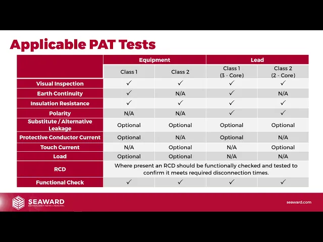
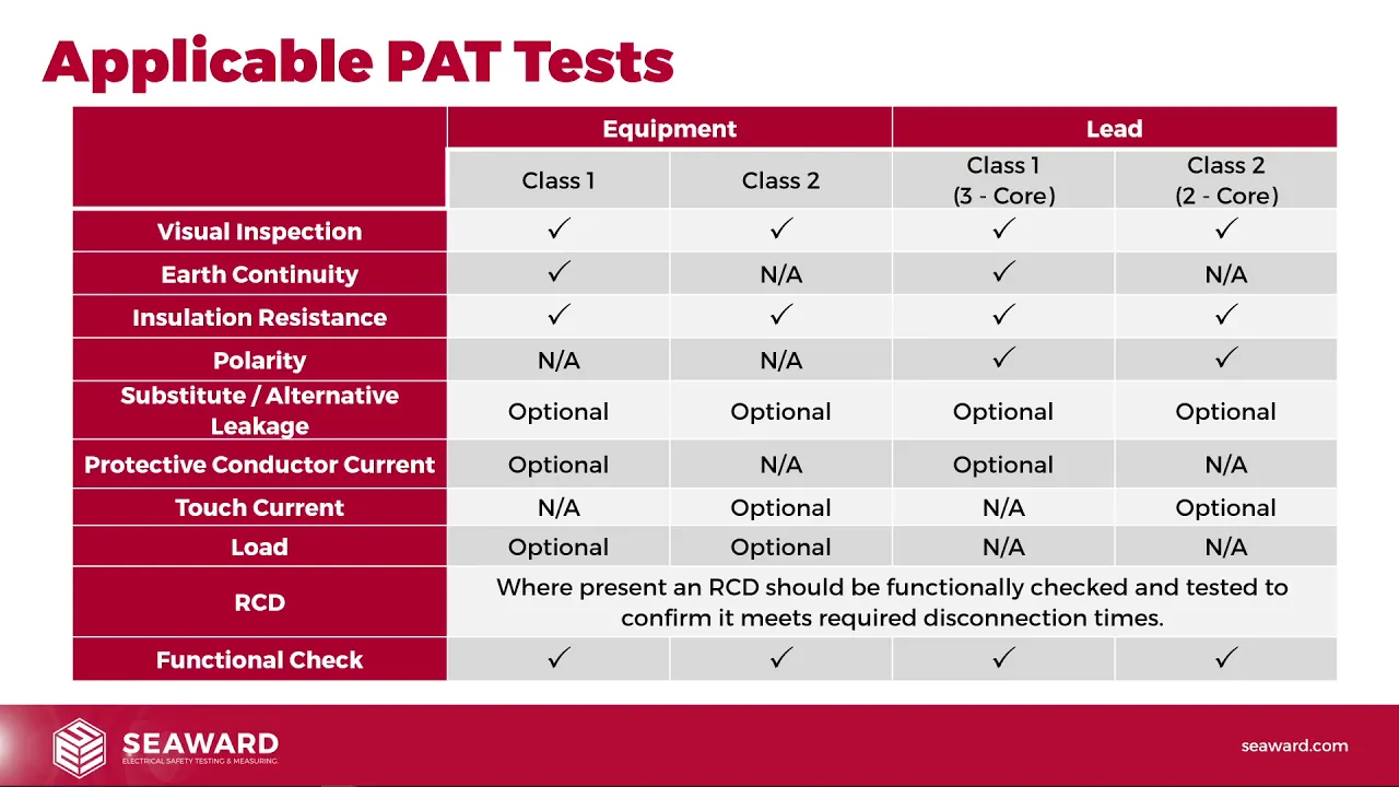
so it actually breaks down what tests we should be carrying out on what equipment so just take a little bit of time to have a look at this now obviously in This webinar we're looking at the basic tests but this includes all of the inspections and tests in here so you can see on here we've even got visual inspection we've got the functional checks listed on here and obviously they would be applicable to all equipment so if we just have a look at class worn equipments we would do a visual inspection an earth continuity test
an insulation resistance test we wouldn't do a polarity test because we can't get To usually get to both ends of the lead to do that although we would visually confirm polarity during the visual inspection something like a substitute or alternative leakage test is an optional additional test same with protective conductor currents torch current wouldn't really be be applicable we tend to do on class 2 equipment you could technically do a touch current test on class 1 but normally we use that for class 2 equipments a load test Measuring the power drawn by the equipment they
aren't the size of the load of the the equipment simmering in kilowatts or kilovolt amps and where we've got an RCD fitted again we would do an RCD test we'd measure the trip in time the disconnection terms of our cds so you can see for class 1 equipments we've got the core tests that we spoke about before and then we've got the optional test the advanced tests and next week we're going to have a look at The you know in session 6 that's where we're going to have a look at those now as we've said
for class 2 equipments we do a visual inspection earth continuities not applicable because there's no earth we do an insulation resistance test polarity isn't applicable because as we said we can't generally check the end so that we would visually confirm polarity where possible such it or alternative leakage is optional protective conductor currents Is not applicable because again there's no earth touch current is optional load testing is optional and obviously where there's an RCD then we would do that test and obviously all equipment would receive a functional check afterwards as well so the difference for leads
here again for class one leads visual inspection earth continuity insulation resistance and polarity so we've got the polarity test there that we're actually doing on Leads because we can get to both ends we get to the plug on the socket end so we can actually test polarity we could do leakage test on leads and sometimes we do do that particularly for for our CD leads and things like that we might want to do these leakage tests on leads it's not common it's not something most people do but it is there as an option we can
do that if we wanted to and an RCD test obviously if we've got our CD leads then we would carry those out now One that's worth a bit of consideration is the class to lead test because remember this is going to be a two core lead so we do a visual inspection obviously being a two core cable as no earth so we wouldn't do earth continuity and in the list it says we would carry out insulation resistance now this is only if we cam and the reason to say only if we can it's because we
do insulation resistance for Class two equipment as you'll see later on between The line and neutral conductors joined together so the two cores joined together and we would test to any exposed metal or conductive paths so if you think about a standard two core cable generally it's going to be plastic or you know PVC so we're not going to have any exposed metal parts so if we haven't got any exposed metal parts that test is not really applicable for that equipment we can't carry it out so if we had got plus two leads to core
cables And maybe we've got a metal shroud on the connector or something like that yes we could do that we could check to that metal shroud or if there's a metal plug or whatever we could check to that but we would only do that if there's exposed conductive parts to test two sometimes you'll see quite often people will do the test and they'll just go and clip the lead onto the plastic or the rubber and actually it's a nothing test it means nothing We even see people do the test where do the test and they
don't even click me at least leave the probe hanging on the desk and it's not actually - in the test and they believe they're doing something you know so yeah it's passed the test well it will do because they're just testing fresh air well the testing rubbery you know they're not checking to any exposed part so it's a it's a nothing test so just be aware of that with the insulation although yes we Would do technically on here it's correct to say we would do an insulation resistance test on Cluster equipment that is only if
we've got exposed conductive parts on that lead so if that extension reel have metal parts or those metal parts on the connectors then we do that if you can't then it's just not applicable we can't do it from that side of things in which case we'd probably just do a visual inspection again for polarity with class two cables quite Often you'll find that with class 2 equipment it's not actually priority conscious we've all seen those sort of two core figure-of-eight style looking leads on the end and it's not a priority conscious connector you can put
the connector in either way round so because you can put the connector in either way round there's no point doing a polarity test because it's not a polarity conscious connector there's no right or wrong answer however if we did other Connector that was polarized that did have a correct polarity then we would be expected to test that to make sure that the connectors were wired up correctly obviously again we've mentioned on here the substitute alternative leakage test or at which current testers are optional again only if we've got parts to test - only if we've
got conductive parts that we can carry out the test - and the RCD test in there again if we've got our CDs on there we would want to check the Disconnection times of those are CDs as well and as I said everything would get a functional check so everything gets a visual inspection everything gets a functional check and you can see the options that we've got in here so within the webinar today with in today's session session 5 we're going to be talking about the basic tests that sort of continuity insulation resistance and polarity and
then next week we're going to be talking about the more advanced Test the leakage tests the RCD testing so again we'll cover all of everything that's on this table over the next two weeks but really with today we're going to focus on the court so now let's look in a bit more detail of earth continuity testing the safety of all class 1 equipment relies on a good low resistance lateral connection between earth metal paths and the earth connection in the fixed electrical installation it's therefore essential That we confirm this connection by measuring its resistance between
the earth metal parts and the equipment's earth connection usually the earth pin on the mains plug or the earth terminal within a fuse connection units all cooker outlet a low resistance reading signifies a good electrical connection however a high resistance reading may indicate a poor connection within the plug all the appliance or damage to the protective conductor within the cable So what do we got here so let's have a look at the diagram so this is a diagram of a typical piece of class wall equipments and I think we looked at this sort of diagram
when we when we look back at the different classes earlier on and we've obviously got the line the neutral they are powering the load so that could be the lamp a heated element whatever it is within the motor within the equipment and then we've got our earth metal part so we've got our Earth's enclosure there that dotted green box that you see on there that's the the earth enclosure and that enclosure is then connected down to earth or the earth pin on the plug or as we said before that could be the earth connection within
the fuse connection units or the cooker switch or whatever it is so we are checking between the earth point so the the earth terminal the earth pin on the plug and we're measuring the resistance between there And the earth metal parts so effectively the Green Line you can see on here that's the bit we're checking and we're checking to make sure that that's got a low electrical resistance so the resistance is measured between the earth pin on the plug or earth terminal and the earth metal parts of the equipment on the test this test proves
the presence of earthing within the equipment its lead and the plug so here you can see a picture of the the Test actually being carried out using one of our our Apollo testers and you can see the test connections so the test is performed by connecting the plug of the equipment to the eut socket on the practice that's the equipment on the test socket the 3-pin socket on the path tester and then connecting the test lead to the Earth's metal parts so you can see on the case here in there in the picture that we've
got there we've connected the test lead with the croc Clip onto the earth metal parts on the toaster so we know that they're earth metal parts so we've checked those we've gone through some times remember we talked about in the past that you may get all the earth metal parts so parts that are there just for sort of you know as part of the equipment they're not part therefore the electrical safety so again you're not always sure sometimes if you get in Earth's parts or on earth paths but in this case the connection on The
toast though we know it's an earth metal part we've connected that through so that enables us to check the earth in the plug the lead and the appliance to make sure that it goes all the way from the earth pin all the way through so care must be taken though to ensure there's a good connection between the test probe and the metal parts on the test so remember we're trying to measure very low resistances so if the part you're measuring is dirty covered in Paint limescale rust corrosion any of those sort of things it will
increase the resistance so what you can find is that it can fail the tests purely because not because there's anything wrong with the earthing of the appliance but because where you've connected your test probe on to is not allowing a good low resistant connection you've got what's called contact resistance so you may need to actually you know wiggle the probe around a bit scratch a little area Away try and find a clean spot sometimes you might even need to use you know an abrasive or something like that maybe to clean say a kettle element to
clean the limescale off to get a good contact on there so it is really really important you get a good low resistance contact and you maintain that contact throughout the test because if you get a bad contact you may be failing equipment that's actually nothing wrong with it because of your Test setup so always be careful of that when you're making the connection make sure you've got a good clean low resistance connection so what are we actually trying to measure what's the pass/fail limits for if continuity how do we know if it's a pass or
it's a fail so the resistance of the total earth path is made up of the resistance of the equipment's earth path so we'll see there we've got there the depiction of the kettle we've got Diagram on the cat-lair so there's two bits here we've got the earth path within the kettle and we've also got the earth path within the lead and the plug so effectively we've got these two parts and these two parts make up the total earth path so to pass the value obtained must be less than or equal to naught point one ohms
so we allow naught point one ohms for the appliance the appliance itself should be point one of an ohm or less usually it'd be significantly less Than that but we allow point one ohms for the appliance itself and then we add on to that the resistance of the cable so the resistance of the cable as we've spoke about in earlier sessions depends on its cross-sectional area and its length so realistically we're allowed whatever it's you know the laws of physics dictate it's allowed to be we were allowed the resistance that it's meant to be there's
no set limits particularly for the cable other than The fact that it should read the same resistance as a cable of that length and cross sectional area because if it's not reading the same as the you know a cable of its cross-sectional area or length that could indicate there's a bad connection in there it's substandard or counterfeit cable it's not sufficient in cross sectional area you know it's frayed all sorts of things so the limit and the pass/fail limit for earth continuity is less than Or equal to point 1 plus R in ohms so the
unit for this is ohms and it's got to be less than or equal to point 1 plus R now in many cases people just use naught point 1 because we know we're allowed point 1 plus R so if it's under point one then it's automatically a pass anyway so generally most people looking for a read he when we do an earth continuity test of less than or equal to point and warm However we are allowed point one plus the resistance of the cable so let's have a look at the next next slide and we'll see
examples how we calculate that so here we go we've got an example so it's saying what is the limit for a kettle and it's got a two meter cable and the lead is one millimeter squared cross-sectional area so we can obviously measure the length of the cable or we could estimate the length of the cable two meters and remember when we looked At this before if we look on the side of the cable we'll see this in this case three g 1.0 millimeter squared such tongs it's a three core cable with one millimeter squared cross
sectional area so what it's telling us is we know the length and we know the cross-sectional area now from the cross-sectional area we can use this table here so if you have a look at this table the table gives us the resistance per meter the ohms per meter for that size of cable so For a one millimeter squared cable it's nineteen point five millions per meter thousandths of an ohm per meter and that translates to naught point naught 1 9 5 ohms per meter so for every meter of that cable the earth wire should read
naught point naught 1 9 5 for every meter so how do we actually work out the pass/fail limit well it's just a bit of maths so it's point one for the appliance naught point naught one nine Five multiplied by two because we've got two meter so we take the the value per meter and we times it by the two meters so that gives us naught point 1 plus naught point naught 3 9 add those two together we get a limit for the earth continuity pass/fail limit for this particular appliance our kettle with two meters of
one millimeter cable of less than or equal to naught point one three nine ohms so when you measure the resistance with your part tester if you Get anything less than or equal to naught point 1 3 9 ohms it's a pass if it's more than naught point 1 3 9 ohms it's a fail there's a problem there somewhere you've got a bad connection you've got afraid cable something like that and you'll have to investigate and see what's going on so it's important that we understand the pass/fail limits for every piece of equipment we test so
that we understand where these things fit in and we're not failing items that Should pass or passing items that should fail and quite often this is one of the key things that people was particularly in a new two-part test II don't understand and they'll get the computer will pop up and say or the test will pop up and say it's failed and we go alright it's failed put a fail sticker on it took it away and actually it was because we were applying the wrong pass fail limits you can imagine with this particular kettle if
we applied a Pass/fail limit of 0.1 ohms so we said right we set the part test drop anything over point 1 ohms will fail anything on the point 1 ohms as a pass and we got a reading of say 1 point 1 2 ohms the Pat tester may say it's failed because we've set the limit to point 1 but the actual limit we should have applied is naught point 1 3 9 so if we got a reading of 0.12 that should be a pass but we may be tempted to fail out because we've set the
Pat tester upon point 1 So it is important how you set the testers up understand the pattern pass/fail limits applied by your particular tester and how that works and this is why it's important to actually read the numerical values off the tester and actually see what the real readings are rather than just going by the the beep you know to say it's past or the tick to say it's past you need to actually look at the numbers and the numbers give you an idea of whether That's close to the limits well under the limits you
know a really obvious pass or is it just on the edge and again by doing that we can interpret these results and we get a good idea of what's going on so quite often where people go wrong is with things like extension leads so if we've got an extension lead here what would be the limit for a 10 meter extension lead with a cross-sectional area of 1.5 millimeters squared so again we've got the diagram Here we've got our extension reel we've looked on the side of it we can see it says 3G 1.5 millimeters squared
so we know it's a 1.5 millimeter squared cable it's 10 meters long so we go to the we go to the table we have a look in there it's thirteen point three million per meter which is naught point naught 1 33 ohms per meter so point 1 for the real plus naught point naught 133 per meter times by 10 meters that comes out to point 1 ohm for the real plus naught Point 1 3 3 ohms for the lead the 10 meter lead add the two together gives us an overall pass/fail limit of less than
or equal to naught point 2 sorry naught point ya - 3 3 ohms so anything less than or equal to naught point 2 3 3 ohms is a pass anything greater than naught point 2 3 3 ohms is a fail now you could imagine if we were using a path tester that was set to point 1 it's gonna come up with a fail it shouldn't be a fail But it's gonna come up with a fail because again we're applying very tight limits to it if we've got a test their like some of our prime tests
we set the prime tester pass/fail on point two so again you could test this lead with the prime test it would come up and say it's failed however what you should do is look at the numbers and actually make your own decision on that say oh no it's failed because it's a long lead it's not failed because it's a Fault it's failed because we're actually applying quite a tight limit to it and it should actually be this value so again really really really important that you take the time with each piece of equipment to understand
what what region am I expecting almost before you press the button you should know in your head what am I expecting to pop up on the screen there for earth continuity and that's the only way you're gonna know whether it's good or whether it's Bad whether it's a pass whether it's a fail is to actually be able to do that to look at it and say yep I know what reading that's gonna be you press it comes up and you say I'm expecting a reading of under 0.233 you get a region of about point two
you think yep that's about what I was expecting this is this is good I'm happy with this whereas if you expected a reading of about point one and you get point two who is anything could hang on a minutes this Should be lower than this what's going on is there a bad connection am I not made the test connections properly so always always always take the time to really look at your pass/fail limits for Less continuity and make sure that you know what you've expected that you've applied the right limits to it because the amount
of times that people fail equipment because they're applying the wrong limits it's it's scary it really does happen a lot because people just Don't understand the limits and it's just tester says no you know you got to fail on the test report you mom for attend me to lead and then you know cut the plug off took it in the bin and you know and that that's equipment that should have passed but it's because people don't understand the limits properly from that side of things so all we spend the time do some practice with this
look at a few appliances you've got around your home or your workplace work Out what the position should be measure it see if you're right so at seaward we've got a few options here to help you because obviously this is this is something that does catch a lot of people out now in addition to things like our pack guide we've got our pack guide that tables in there obviously the tables in the int code of practice but with our automated test as our Apollo tests as you can see on here we've got the limit calculator
function So when you carry out on earth continuity test if the test fails it'll say do you want to do the test again you'll say yes please and then there'll be a picture of a calculator and the picture the calculate was the limit calculate you press it and you get a screen like you can see here and it says what size cable is it and how long is it you put those values in and it works out what the actual pass/fail limits should be and then when you accept that it then Applies that to the
test and says oh no actually based on what you told us that's a pass and it will carry on with the test so these things are built into the testers to help you with that unfortunately obviously we can't build that into things this the simple test is like the manual testers because there's no keyboards and it'd be quite difficult to do that but we have actually got some apps available as well so with the new C would pop mobile app again we've got a Cable resistance calculator built in so when you come to do your
you earth continuity test you can use the resistance calculator you can put in how long the cable is what the cross-sectional area is and it'll work out the limits and apply those in there for you and we've also got an app specifically for calculating lead resistance so we've got the lead resistance app you put in a length of the cable the size and it works out the Resistance for you so we've got options there's options there unfortunately both those apps are only currently at the moment available on Android but we are looking at hopefully getting
soon getting some iOS versions to those out but for those your Android users was to apps there that you can use and obviously when you're considering buying a new part tester just have a think about getting the part testers that have got these limit calculator features Built-in because it is really really important and it will really help you from that side of things so just to finish up with earth continuity testing just a few points that we want to cover in here so prior to carrying our earth continuity tests it's advisable where possible that you
zero or null your tester to mitigate the effects that test lead resistance has on your test results if it's not possible lead resistance can Be measured and deducted from the test results obtained so if you think about this if you're measuring and want me to lead with a one meter test lead the rly the resistance of that test lead actually adds to your overall results so what you should be able to do is to zero that or remove that resistance so with something like the Apollo we can go into the settings we can measure this
the test lead resistance and then we can press null and what it does it then Deduct that automatically from all future readings so you don't get the effect of the test lead resistance there so sometimes we've had people fail equipments and they're failing equipment because they've got a dodgy test lead they've got an old test lead and the connections have started to go on the test lead so everything's failing because it's adding that test lead resistance onto every reading and that's just pushing things over the limits so Always make sure you've got good test leads
obviously by new tests but where possible null or zero that if you can't do it you can just measure the test lead resistance and then remove that from all your all your reading so you know automatically the test lead reads nor point naught 5 so any readings you're recording just knock nor point 5 off that naught point naught 5 off that and obviously that's there's a way of manually correct in your reading so just Be aware of zeroing because again we're talking about very very small resistance values when we do an earth continuity and even
the resistance of the test leads can affect that now the next thing in modern battery-powered instruments it's normal that earth continuity tests are carried out at a test current of 200 milliamps so point to of an amp and see what instruments also include our zap technology for increased results stability Yeah just important that I talk to you about this because older testers we used to carry out testing it sort of 25 amps 10 amps those sort of things where is most modern battery-powered testers pretty much all testing is done at 200 milliamps now 200 milliamps
is quite a small reading it's got a small current now the reason we do that is warm it allows us to use battery-powered testers without running the batteries down so the portability And the speed of test and all those sort of things is great but the downside is by using 200 milliamps what you're doing is you're actually using quite a low current so if you have got limescale corrosion dirt those sort of things they are going to be more affected by that than a higher test current would be so in the early battery power testers
people quite commonly were having to you know use bits of Emery cloth and some paper to clean things down to get a very Clean connection before they they could actually do these tests or if they did do the tests they'd find one minute had passed then it would fail and it passed and it just came down to whether you've got a good contact on the point of test so see what instruments we came up with this zap technology and the zap technology actually spikes the test currents at the start of the test and what that
means is that you do get a reliable repeatable earth continuity Test without the need to constantly have to keep going in and cleaning parts and all those sort of things so you get a lot better results stability so it is important if you are carrying out any of these tests generally we'll use the two hundred million tests because a battery-powered testers the two hundred million tests is also a lot safer for sensitive equipment you obviously imagine something like a PC or something like that and then you Start putting 25 amps down the earth path that
could potentially damage the equipment so again the 200 milliamps test we generally use it one because for battery-powered equipment so we can we can use battery-powered path testers more portable and also because it's safer for the equipment they're actually testing but Siward testers include the sap technology and that means that it's really reliable you do get a lot more consistency with your readings so where Your tester has the facility you may wish to perform the continuity tasks that hiatus currents for example 10 or 25 amps while these tests are more robust so they'll actually put
the equipment on the more stress so you're actually putting some heavy current down on earth path so potentially if there is a problem with the earth path it will cause it to fail you know if you've got a frayed cable or something it will actually burn it Through and and you'll expose that fault whereas with a lower current you may not do that the problem with this is that obviously equipment can be damaged so the test of the person carrying out the test must be really certain that your own you're gonna carry out these high
current tests on equipment that can't be damaged so always be careful if you are going to carry out a high current test like a 10 out and test or a 25m test because you've got a high chance of Actually damaging sensitive equipments if you apply that test in the wrong way if you want to do it on leads and you know some less sensitive power tools and things like that that's absolutely fine but again this is only generally available on sort of mains powered bigger chunkier testers may be older testers this isn't available and your
battery-powered your modern battery-powered testers so again just bear those things in mind and really It's worth with earth continuity testing to practice and just practice those tests and you know it is something that you'll get more into interpreting the results being able to find their decent test points on the equipment to test and things like that so again that sort of continuity testing so in this section we're going to look at insulation resistance testing the purpose of this test is to confirm that the various insulator is within the plug Supply cable and equipments have sufficient
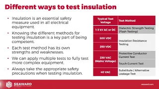
electrical resistance to separate live parts from Earth in class one equipment and live parts from exposed conductive paths in class 2 equipment typically on the normal operating conditions insulation needs to be capable of withstanding the supply voltage it is for this reason that when testing insulation resistance it's desirable to use a suitably high voltage often 500 volts DC which will place the Insulation under a degree of electrical stress allowing us to be confident that the insulation will perform correctly under real-world conditions just added a little note in here some equipment can be damaged by a
500 volt test and in these cases testing at 250 volts DC is preferable yeah just be careful with that because we are using 500 volts and 500 volts is the sort of standard voltage recommended in the IAT code of practice but there is some Equipment it's quite rare equipment you know you don't always come across equipment but there is some sensitive equipment where a 500 volt test could actually cause damage to that equipment so in those cases always if you're in doubt test at 250 volts DC instead but obviously at 250 volts DC's test is
not putting the the level of stress on the insulation that we want you know we've got 230 volt equipment we're putting 500 volts through it to really test it out Make sure that installations okay if we're taking 230 volts equipment to put in 250 volts through it it's only that little bit more than supply voltage it's not really gonna do a lot more stress again it's more than the supply voltage so we're still you know confidence really there we will detect faults but it's not quite the same as 500 volts so it is always a
problem a lot of people and particularly people who new to PAP testing struggle with it's when during There were 500 volt tests and when there were there were 250 volt tests and generally rule of thumb is anything that sensitive or surge protected equipment you'd probably want to do a 250 volts test anything else again we'd probably go with a 500 volts test but anything sort sensitive electronics anything it's quite expensive or fragile or anything like that always default to the 250 volt test because it's been on the safe side with 250 volts you're not going
to Damage equipment whereas the 500 volts you runner a chance it's a very slim chance but you do run a chance of damaging equipment by performing that test so let's have a look at the insulation resistance testing on class warm equipment so it needs a little bit different between class one and class two because obviously on class one equipment we've got the earth and class two we haven't so you can see on here That we've actually got the the layout again the diagram and the way we're actually carrying out the test in this case is
in class one equipment a test voltage of 250 or 500 volts DC is applied between the live conductors so remember when I say live conductors we mean though the line and the neutral they're the live conductors and in this case they're actually joined together so when we do the test we join the line in neutral together inside the path tester To actually avoid any chances of putting 500 volts across the supply so by shorting those two together we make sure that we're not going to be injecting five intervals into the equipment which definitely could damage
it so we're measuring between those two join together and the earth conductor so obviously on a piece of class 1 equipment all of that can be done at the plug all of that can be done we don't need any test leads for this this Because we need the line intial and the earth and all of those things we've got at the three pin plug a reading greater than or equal to 1 megaohm 1 million ohms is a pass and indicates that the insulation is sufficient to separate the live parts from earth parts so again just
looking at the diagram here there's a few things at the top there you'll see one we've got a fuse the plug top fuse or the fuse in the fuse connection unit that must be intact if the fuse is blown We're only going to be testing up to the fuse so we're not actually going to be fully testing the equipment we could have a fault after the fuse on the line side and actually we wouldn't know so the fuse must be intact so part your visual inspection we look at the fuse but generally what you might
want to do with the continuity tester is just perform a quick continuity test on that piece of it on that fuse and for that Piece of equipment to make sure that it's correct the other thing that we need to do is we need to make sure that the which to the appliance is closed that the switch is in the on position again if we carry out the test in the switch isn't in the on position we're only checking upper to the switch we're not fully checking the equipment after the switch so again if there was
a fault after the switch we wouldn't Detect it by doing this test so very important there are two things before we do it is check the fuse make sure the fuses is there and it's working and also that we've closed the switch and that we've we've made that switch connection so when we do that then we apply the 250 or the 500 volts DC and that puts that voltage across the insulation the gray insulation you can see on there and make sure that we've got no short circuits breaking down between the earth metal Parts and
the live parts and I said the pass/fail limit is greater than or equal to 1 million ohms for class 1 equipment nice and easy to remember for class 1 1 megaohm now here you can see the actual test connection as I said it's pretty straightforward really we plug the appliance into the path tester all of the three connections we need are there presence at the plug and the part test has got what it needs and we then we Make sure that it switched on obviously by pressing the the on switch in this case on the
kettle so this test is performed by connecting the plug of the equipment to the equipment on the test socket the et second socket on the path tester the equip must be switched on prior to starting the test important safety points here care must be taken not to touch the equipment during the test as hazardous voltages may be present so again generally we don't Touch the equipment during the test if it's plastic like this again the risk is pretty minimal but if it's got a metal case on it metal enclosure while we're doing the test if
there was a fault then potentially that 500 volts could be present on the equipment also if you are carrying out tests it's good practice not to do it on a metal conductive surface so you might want to put a piece of ward or a piece of rubber you know rubber mat or something like that Insulate you will amount under your test area to make sure when you're carrying out these tests because if you are doing this on a conductive surface you potentially could make that surface alive so again we don't want to we don't want
to run that risk for the period of tests so importance test connections dead dead straightforward but we can act it up we carry out the test with the switch on and make sure we don't touch it while we're carrying out that test So plus to equipment what's the difference with plaster equip well in this case we haven't got earth metal parts we've got exposed metal parts of exposed conductive parts I've used the term conductive here because sometimes we can have parts that aren't metal and actually do conduct electricity and sometimes you may get areas like
parts of equipment that's actually contaminated so it might be contaminated metal door store swarf or things like That that's actually you don't think of it specifically as a metal part but it's something that's contaminated with conductive material so exposed conductive paths so in class 2 equipment a test voltage of 250 volts or 500 volts DC is applied between the live conductors line and neutral joined together and any exposed conductive parts in this case because it's double insulated so with two times the strength of insulation so remember the pass/fail Limit for class 1 was 1 megaohm
for class 2 double insulated we have a pass/fail limit of two megaohms so the reading must be greater or equal to two megaohms to pass and this indicates that the insulation is sufficient to separate the live parts from exposed parts so again you can see here the test setup we can act up the plug to the to the to their part tester but in this case we need to use a test probe as well whereas with class one Equipment we've got everything we need we were using the earth effectively as our test probe with class
2 equipment we need to use a separate flowingly test probe and we must place that onto the exposed conductive part so we need to actually make contact with there make sure we've got a good low resistance contact with them so that when we actually carry out the test if they were to become live we would actually pick that up so you can see here with this Drill chuck if the the load if the live parts are actually to come into contact with that due to a fault we would have to actually put the test probe
onto that and do that test before we pick that up so if you have got multiple exposure conductive parts it would be sensible to repeat the test and actually repeat the test with the test probe connected to each exposed conductive part to prove that each one of those was actually separated from the live parts by at Least two million ohms so here you can see an example where we've got a lump this is a class two lump it has got exposed conductive parts you can see the neck of the lamp there is an exposed conductive
part so we connect up the the lamp to the pad tester but in this case because it's Class two we're using the test lead and the test lead is connected to those exposed parts so we're checking to make sure those exposed parts aren't shorted Out to the line and the mutual within within the lamp you can imagine the fault the neck of the lamps but bending it wears through the cable the line or the neutral is in contact with that live part and then again if we would use the equipment and touch that we could
get a shock so what we're doing here is we're proving the insulation between the live parts and the neck of the lamp so it says here this test is performed by connecting the plug of the equipment to The eut socket on the path tester and the test lead connector to exposed conductive parts the equipment must be switched on prior to starting tests it may be necessary to repeat the tests for each exposed part so if we got more than one exposed part we need to repeat the test allows we said before care must always be
taken not to touch the equipment during the test as hazardous voltages may be present so again that's a typical test connection there we need To make sure that we're actually able to connect this now again like I spoke about earlier with leads when we're talking about test sequences what if your cluster equipment has got no exposed conductive parts good question so what do we do do we just connect the croc clip on to fresh air do we leave it disconnected from the PAP tester do we clip it onto a bit of plastic or do we
actually do the sensible thing and say well actually There's no meaningful test we can apply to this in which case we omit that test altogether we don't do the test because it's not actually a meaningful test remember we only apply Pap tests where it's relevant where it's gonna add something to our knowledge of the safety of that equipment not because we assume we have to do it so we're only doing the tests we only test the things that we need to test to improve our knowledge of its safety if there's no exposed metal Parts or
no exposed conductive parts there's nothing to test - the test is meaningless so in which case don't do the test you can record that down in the comments the way you didn't do it no exposed parts didn't do it no exposed parts that's factored in by the duty older when they do a risk assessment and it may be that you just carry out a good thorough visual inspection and away you go but never feel that you have to carry Out a test when it's not relevant or not important you know doesn't actually tell you anything
and there's so many people where they actually carry out these tests and they'll clip the the croc clip onto the rubber cable go into it or just onto you know anything that can find a little bit of rubber or plastic or leave it hanging on the desk just so they get a reading and it actually means that the tests haven't been carried out properly there's no real you know you're just Wasting people's time there and worst case scenario if anything goes wrong and there's an investigation and they look into it you know say well this
guy's been testing this for years what's he actually been testing does he know what he's doing is he competent so again don't feel pressured into off gotta do an insulation resistance test on class 2 if there's no exposed parts you can't do the test exactly the same when we talked about doing no continuity Tests if there's if there's no accessible parts to test to what are you gonna do you can't do the tests don't do the test Oh meet it record why you omitted it that gets factored into the risk assessments and it works that's
that's the process so don't feel that you've got to sort of fudge these tests make these tests up because I've got to do this test on every piece of equipment if he's not possible to do it then obviously we Don't do it simple as that so a bit more information about insulation resistance testing so when choosing to carry out an insulation resistance test the competent person that's the key thing competent person must consider to test out 250 volts or 500 volts the preferred option is to test at 4400 volts however this can damage sensitive equipment
and also can be affected by surge protection within the equipment That's an important point to mention they're actually surge protection within the equipment's a lot of modern electronic equipment now has built-in surge protection so when you connect 500 volts to it guess what it thinks that is a surge so it operates the surge protection and you get a low insulation resistance reading because what the surge protection is trying to do is it's trying to divert that voltage down to earth to protect the equipment so you Get a low reading maybe point three of an ohm
through point three mega ohms something like that and you think all there's something wrong with this equipment cut the plug off throw it in the bin and then you get the next one you try that the next one you try it on you keep and before you know it you've gone through all this equipment and scrapped it all and actually what you doing is you're not testing correctly you're just operating the surge Protection which is meant to be though it's doing its job and because you've put 500 volts on it when you shouldn't have you're
actually failing equipment that should pass and that's a very common thing people fail surge protective equipment because they're testing at the wrong voltage so always be prepared when you do in a test if it's surge protective equipment drop the voltage down to 250 volts DC carry out the test at 250 volts DC and that will Give you a much more reliable reading for surge protected equipment so if we've got anything that sensitive or surge protected say where any doubt exists we recommend testing is carried out at 250 volts DC and the reasons are recorded in
the comments the duty holder should also factor in the reduction in test voltage in any risk assessments they carry out it should also be noted that equipment with electronic switching or contactors May not be fully tested as it cannot be switched on during the test so remember if we've got something with a physical on/off switch we said we need to place the on switch in the on position so we fully test it but what if you've got an on switch that only comes on when there's 230 volts applied to it like a contactor or imagine
the start button on a computer it's not going to power up until those mains voltage there until it detects mains voltage and you know kicks In that contactor so if we just come along and we do a test on that equipment whether it's a 250 volts or 500 volts we're still only going to be testing up to the switch or up to the contactor so in these cases the tests that may decide to perform a leakage test to supplement the insulation resistance test so we'll talk about this next next week about using leakage tests like
protective conductor current tests or touch current tests to more fully test equipments That's got this type of electronic switching because obviously a leakage test will apply mains voltage to it and we can actually turn it on we can have the equipment running and actually measure the leakage currents and that will give us a good picture of the quality of the insulation and condition of the insulation you'd always do an insulation resistance test first because who knows there might be a fault with the lead there might be a fault with the The initial stage of the
equipment so it is important that we do the insulation resistance test anyway but we can always supplement that with the protective conductor or at which current has to actually find out more about the condition of equipment after the switch so again it's this combination and this is about being competence and understanding how we we use complementary tests to find out what we want to know is that equipment safe for Continued service so the last the basic test that we're going to look at today is the wiring polarity test and it really does exactly what it
says on the tin it checks the polarity of lead wiring wiring within leads so the priority test is only applicable to detachable appliance leads cord sets like you see on the picture there at IEC lead or extension leads and the reason for that is because we can get at both ends we can get at both ends To actually check the wiring where it's with an appliance we might be able to get to the plug so we can do a visual inspection of polarity within the plug but we can't see inside it where it's wired so
we can't check that it's wired up correctly within the appliance we just assume yep that's gonna be wired up inside there and we have to take that for granted that nobody's nobody's messed about with that but where we've actually got leads and we've got Extension leads then we can actually check the wiring so the polarity test is used to confirm correct wiring at both ends of the lead ie that the line connects to the line the neutral connects to the neutral and the earth connects to the earth that's what we mean by polarity that it's
correctly wired that the polarity of it is correct correct polarization although polarity is checked visually during formal visual inspection it's Often not possible to visually inspect the terminations at both ends of the lead this could be where we've got a molded type plug for example so if we got a molded type plug or we've got moldy type connects at both ends we can't visually inspect the polarity so that lead i've got there on the slide it's molded at both ends we can't visually inspect the polarity so we've got to test it so therefore a simple
continuity test is carried out to Confirm these connections so effectively what the part tester does is it checks the polarity between line and line neutral neutral earth and earth most modern portable appliance testers will have a dedicated test sockets used for lead testing one end of the lead is usually connected into the normal appliance test socket the UT socket and the other end connects into the dedicated lead test soccer they normally a normal IEC lead socket on the part Test you'll see that quite common so here you can see the the test configuration you can
see how it's connected up to the tester so what we've got here is we've got a 4-way multi way adapt to a four-way little extension block and this is actually being tested for polarity using the the Apollo pad tester so the way we've done it here you can see we've connected the plug from the extension lead into the UT socket on the pad tester we've then used our read Seward's lead test adapter the shred our UC lead to actually join from the extension lead socket all the way back into the IEC test socket or the
lead test socket on the top of the Apollo so what we've done effectively is we've created a big loop you can see there we've created a loop comes out the socket round and back into that so we're able to check both ends that that connector and we can actually see that yep the outlets on there on the socket The sockets on the the four outlets on the 4-way multi-way adapter they do actually relate and they're wired up correctly in relation to the pins on the plug so if we were going to change this configuration we're
going to test an IEC lead it's exactly the same all we would do is we plug one end of the IEC lead into the test socket and we plug the other end into the eut socket and again we've got that loop and that's exactly the same if we do in extension reels and All sorts of stuff it's just that loop way of doing it so it's often necessary for adapters to be used when testing the leads with a non-standard configuration it's our end yeah so we might have cloverleaf ends we might have you know 110
volt ends all sorts of things so again what we do is we just have adapters and those adapters just configure either one end or the other end basically back to what we've got so what we've got is an all you see connect On the AC connector and a standard three-pin plug so we just have adapters for say a 1 10 to the 3 pin and a 1 10 back to the IEC lead cloverleaf adapters we can get a little cloverleaf as where it's you plug a cloverleaf onto it and it turns it back into a
normal IEC so again you may need to purchase adapters and obviously at C when we do do a range of adapters and some of our distributors do a range of adapters as well that you can use but it's typical For most people carrying out pad testing to need a large range of adapters the one thing I will say about adapters you just make sure that the ones you've got a safe obviously you know this this is test equipment we do need to make sure these are safe sometimes you get adapters people have just cobbled together
themselves and you know but Heath Robinson so always think about the safety of your adapters when you're when you're buying and constructing adapters So and basically when we've got a non-standard configuration to either end the portable appliance test that will perform a wiring polarity test and indicate any faults found so we connected up with the adapters it carries out the portable appliance test and as part of that we'll do a wiring polarity test and the wiring polarity test indicates the faults now a typical faults that you will get can be an open circuit conductor so
it might say open Circuit means there's a break the circuits open and so there's a break in one of the conductors it could say there's a short between conductors so that could mean that two of the conductors are joined together quite often we'll pick that up with an insulation resistance test but not always so in that case we might get a short reading and the other thing we get sometimes is an inquire in correct wiring fault and that's generally where It's reversed so say a line in the neutral reversed it would actually give you a
reading there to say the wiring is incorrect some of these wide this open correctly so it could be open circuit there's a break somewhere the cables aren't continuous there's a short-circuit two of the cables are connected together or it could be a wiring fault where it's reversed if that's a little line and neutral probably been swapped over in that case So again it's a quick it's an easy test we connect it up sometimes people would repeat this at each socket outlet maybe just to go through and actually put repeats in generally with polarity for something
like you know a sort of a premade a bought in sock it out letter you know extension lead the chances of actually there have been different worrying at each outlet it's pretty slim because it's normally built into it if you've got one somebody had constructed Or maybe it's part of a bench construction where their individual sockets with individual wiring you might want to carry out that test that each one just to make sure that those things are are actually correct but generally with this type of lead if the wiring is correct for one it's going
to be correct for all if it's wrong for one it's going to be wrong for all but that's down to the competent person willing to decide whether they want to repeat that test The child that'll wear the habits just do do one test that tells them everything they need to know so we're at the end of the session now the conclusion so what did we say we were going to do so we said we're going to look at the basic Pap tests we were going to look at which tests were the essential tests the core
tests and we went through man we looked at the table we looked at the basic tests we even looked at the advanced tests in there And we discussed what tests were applicable to apply to class one equipment class two equipment and also class one leads and class two leads we looked in more detail at the earth continuity test how it's carried out what it's measuring and what the pass/fail limits would be we looked at the insulation resistance test and how they're carried out on class one and class two equipment and also what their pass/fail limits
would be and we Finished up with a look at the wiring polarity tests to check that the wiring is actually correct on detachable leads and extension leads so next week we're going to move on to have a look at those advanced Pap tests and actually look at a bit more detail at things like the leakage tests protector conductor and touch' current test substitute an alternative leakage and also RCD testing so at this point now this is where we open the session up to your questions so What you can do to ask the questions is you
just type that into your chat window and then obviously I'll go through and answer those questions so at this point I'm going to stop the video and I'm going to move over to the live session you