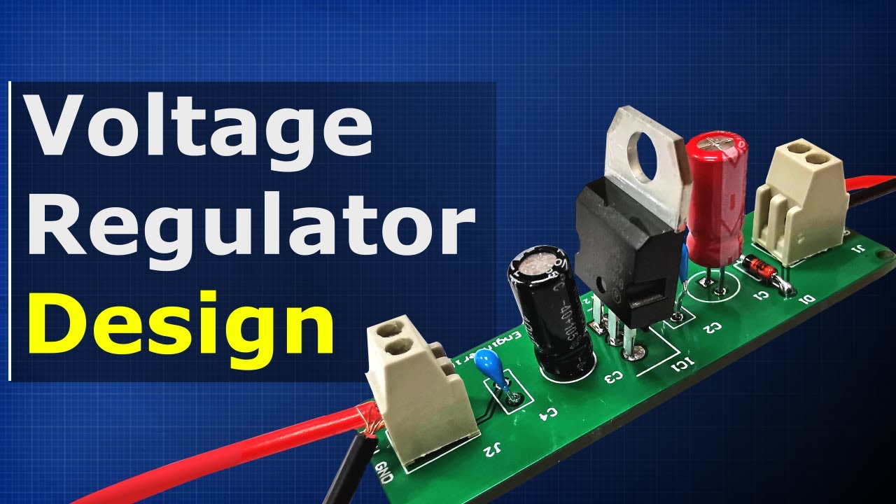
Hi guys! In this lesson, I will basically explain the working logic, structure and types of voltage regulators, which is one of the indispensable circuit element of electronics and used on many electronic cards. Voltage regulators have 3 pins.
The first pin indicates the input, the second pin indicates the ground, and the third pin indicates the output. The main usage task of voltage regulators; is to convert a certain range of DC voltage at the input to a constant voltage at the output. So let's see how it works now.
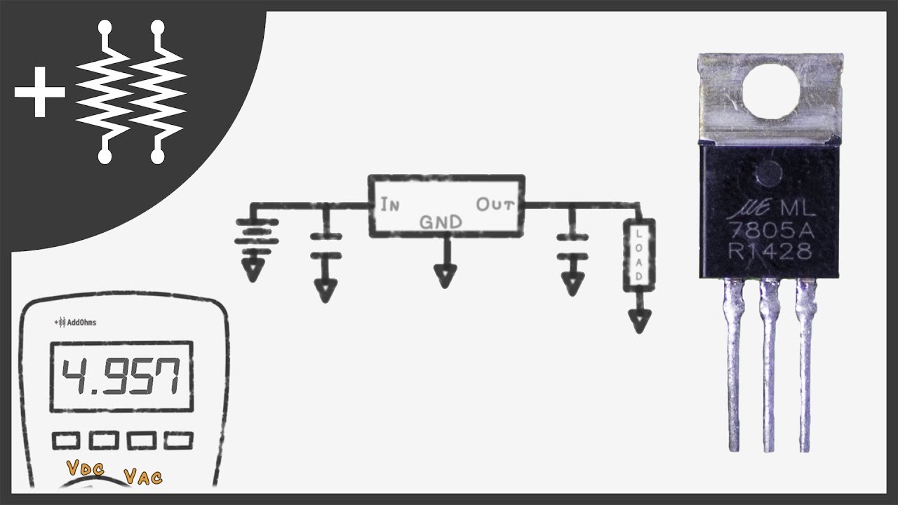
First of all, let's start with how the LM78 voltage regulator series works. For example, when 6 to 35 Volt DC voltage is applied to the input of the 7805 regulators, the output voltage is fixed at 5V. A capacitor is connected to the output to make the output voltage smoother.
The main task of this capacitor; As you can see in the graph here if the output value fluctuates by 5V, it is to obtain a constant 5V by correcting the output voltage with the help of this capacitor. Fluctuations in the output voltage are eliminated thanks to this capacitor we connected, and a smooth DC voltage is provided. So filtering is done.
We can show the working logic graphically as follows. E. g; Let our input voltage be DC 25V.
Thanks to the voltage regulator, this voltage was provided at the output as a constant of 5V. Here, the 7809 regulators are used. In this regulator, on the other hand, the input voltage of 10 to 35 Volts can be supplied at a constant output of 9 V.
Here, the 7812 regulators are used. In this regulator, DC input voltage between 13 and 35 volts can be provided as 12V at the output. Now let's make a simple circuit application.
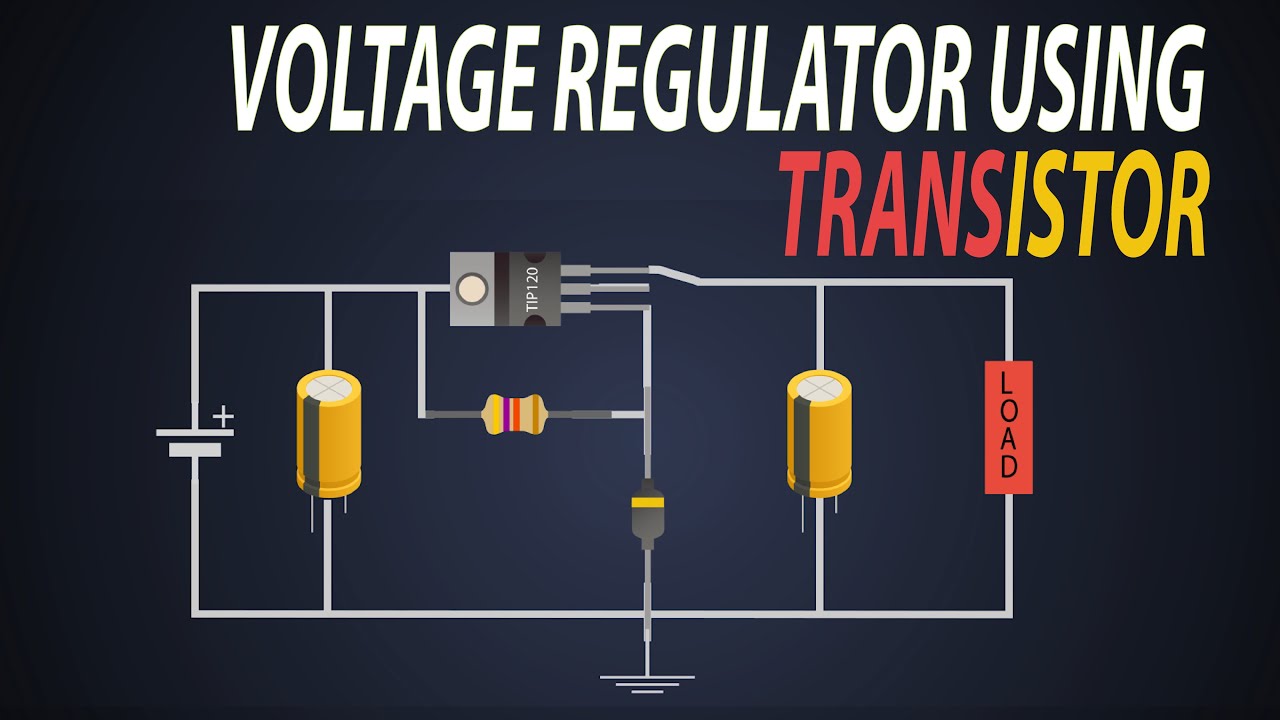
We can show the electrical circuit of the diagram you see here as follows. When a 12V power supply is connected to the input of the voltage regulator, that is, to the 1st and 2nd pins, the output of the 7805 regulators can be taken between the 3rd and 2nd pins. Since the output voltage is 5 volts, the LED lights up in this way with a 330Ω resistor in this regulator.
To visualize this, we can set up a circuit like this. This circuit includes a 12-volt power supply, a 7805 regulator, a 330Ω resistor, and an LED The 12V at the input is reduced to 5V at the output. With a 330Ω resistor, the LED gives light thanks to 5V.
If we used the 7809 regulators, we would have to use a 470Ω resistor since its output voltage would be 9V. Now let's look at what the letters and numbers on these regulators mean. This part shows the voltage regulator series and that part shows the output voltage.
E. g; The output voltage of the LM7805 regulator can provide 5 Volts and up to 0. 5 Ampere.
In the L7805 regulator, the output voltage is still 5V, but it can provide current up to 1A. In the L78S05 regulator, the output voltage is still 5V, but a current up to 2A can be provided. In other words, all of them have a fixed output voltage of 5V, but the current value they can withstand without deterioration is different.
For example; In the LM7809 regulator, the output voltage will be 9V and can withstand a current value of up to 0. 5A at most. Here we should pay attention to this.
The voltage value can be fixed, but the current value changes according to the resistance value of the load connected to the output. In other words, fixing the current value is out of the question. We need to choose a voltage regulator according to the maximum current in the circuit.
Voltage regulators are not used in very high-current circuits. It is generally used on electronic cards. If we want to stabilize the voltage by reducing in a circuit with a very high current, we need to use a DC-DC step-down converter, whose picture and circuit structure can be seen here.
There are also voltage regulators that produce negative voltage. The names written on them start with 79, not 78. E.
g; With the 7905 regulators we can get a constant -5V at the output. In the same way, we can obtain a constant -9V at the output with the 7909 regulators. Their input, output, and ground pin names differ.
So in this regulator series, pin 1 is ground, pin 2 is input, and pin 3 is output. It is necessary to pay attention to this when connecting. Adjustable voltage regulators are also used in regulated power supplies.
LM78317 is the most commonly used voltage regulator. Here you see a circuit diagram using this regulator. The output voltage can be adjusted with the value of the R2 resistor in the circuit.
By using a potentiometer instead of this resistor, an output voltage of the desired value between 1. 5V and 37V can be obtained with a DC input voltage of 40V. There is also the AMS1117 regulator used in electronic circuits.
This regulator has 3 pins again. In this regulator, the 3rd pin is input, the 2nd pin is output and the 1st pin is ground. In this, the DC input voltage between 6 and 35 volts is fixed at the output of 3.
3V. It is widely used in many electronic boards. You should choose a voltage regulator according to which voltage and current values are required for the circuit you will make.
The regulator should be selected according to the voltage and current needs of the circuit you will use. The types and working logics of Voltage Regulators are basically like this. I hope it was helpful and you liked it.
Hope to see you in the next lesson. Goodbye.