Soon so welcome everybody everyone to our uh series of webinar from fluke networks as usual we have opted for [Music] support you in your business and you work through some uh additional technical discussions product technologies and uh information to share with you During those pandemic days where we cannot possibly meet in person and we are wanted to to expand our knowledge to you as well as far as we can during those weeks and thank you very much for this continuous uh attendance for many many of you guys we have uh seen people in our webinars
in the numbers of hundreds of people so that's great to to see you guys and Always welcome to see more of you and in our more webinars to come uh in our session today we will be talking about the best practices for testing fiber optic cabling so it's one of the topics that we've been asked to to go into some details which due to the time of one hour of a webinar it's a bit tight to talk heavily deeply but we will be Trying to scratch some surfaces around it and make sure that you guys
enjoy this session and enjoy the topics that we will go through them so a bit of loop networks fluke networks has been in the industry of testing and measurement for many many years and we have a load of expertise in our team to serve you and serve the customers with Related to fiber and copper optic fiber optics and copper testing in the field so we have a number of hundreds of years of expertise we have the biggest i would probably say we are the biggest library of knowledge base of our and articles that tackle technologies
and techno technical details on how to do testing and how to to understand the testing of copper and fiber we have multiple services centers Around the world as well we have something that was stuck in my mind that we have almost 25 tests every second if you do that in an hour in a day in a year we're almost looking at two million two plus million test results a month uh over two million test results and we look at the year we're almost looking at three quarter of uh three quarter per million of test results
So that's that's a lot so i was talking two million uh a day not two million a a month sorry but yeah that means we are serving you guys and helping guys to do as quickly as possible test results in the field and we have been always present in the standard body so we are able to cover you and support you when it comes to uh latest standard updates one thing i Wanted to highlight here as well that we have a team of support engineers in our technical assistance center spread across the world from the
asia pacific to the us so we have around the clock teams to support you in your questions and problems uh always reach out to support they will be here to support you and help you with any questions you have as an agenda Today we're gonna talk a little bit about safety and you know fiber optics is not always uh something that we need to to miss or forget the safety aspect of it we're gonna talk uh slightly about the cleaning and inspection uh we had a few weeks back a session dedicated on fiber cleaning and
inspection if you have not attended that please reach out to us And my colleagues salah and runner will be able to uh help you uh sending the link of that webinar so you can attend and then we're gonna talk about the tier one testing what does it mean tier one testing which is the loss testing and what's tier two testing which is the otdr testing before i continue furthermore uh uh i didn't say in the beginning that my colleague salah and vernon are Joining me as co-hosts in this session to help you answer and attend
the questions that we have and if there's anything we can help we will be directly answering you we will have more people joining us from the technical assistance center as well and if you have any questions during the course of the presentation please go to the question and answer q a tab In the in zoom and ask your questions and we'll be more than happy to answer you straight in to you so looking at fiber is one of those biggest mistakes that anybody could tell and it's been always the nightmare fiber has been the question
of safety with so many installers and so many technicians and engineers in the world so why is that because fiber is being Launched on a wavelength that we cannot see it's called an infrared and when we talk about infrared it's not visible to the eye but it is very harmful to the eye and that's why we see the infra red in a non-visible wavelength that means we cannot see and what we cannot see could cause harm without even us knowing that's why they see a lot of warnings on the fiber uh cabling systems or on
the fiber Equipment to not look into the uh cable or do not to look into your sfb and look if there's a light coming out because eventually you're not seeing the light but you will probably damage your eyes so as a consideration they consider always that the fiber is live and act upon it don't look straight in the fiber don't Look into it stay away from it don't approach a patch panel with open uh ports make sure that they are all covered with dust caps and whenever you need to do any work on the fiber
just go and use a an electronic inspector with a camera and a screen that you can see what's going on rather than using the optical camera which can increase the damage of your eyes so Dirt has been always around us for some some of us dirt is fun to play for those kids uh yeah they always love to play with dirt and mud and stuff but it's for fun yes but not for fiverr because dirt is a very big cause of a bad connection or bad links in our fiber why of that because statistically 85
percent Of the fiber failures are coming from contamination so you know the fiber coming down from multi-mode 50 micron to the single mode 9 micron we're talking about very tiny little piece of area that we send the light in and our hair is 75 microns so it's even smaller than our hair that means we cannot see and we will not be able to see what's going on here For that we need some specific tools to help us observe what's going on in our connector and this is a case of a connector that has been damaged
because of a mating from a dirty connector that has some uh contamination on it and the contamination caused a permanent damage on that connector that's why this kind of observation needs to be Done we need to clear our connector before we start testing or connect that connector to an active equipment and if i cannot clean the connector don't try anything more replace if it is a patch code throw it away replace don't use damaged connectors to connect to your network because you can cause more harm than you could do for yourself So again equipment repair
will be there watch it out so let's take another scenario which we discussed before many times and we always talk about it do it is contagious so you imagine i'm having a very lovely connector in my patch funnel beautiful clean now i bought a patch code that i didn't know that it was dirty and i connected that Connected in the patch code to the clean connect and the patch panel and the result would be that the connector i have in the patch funnel now is contaminated and will cause me some failures or some drops in
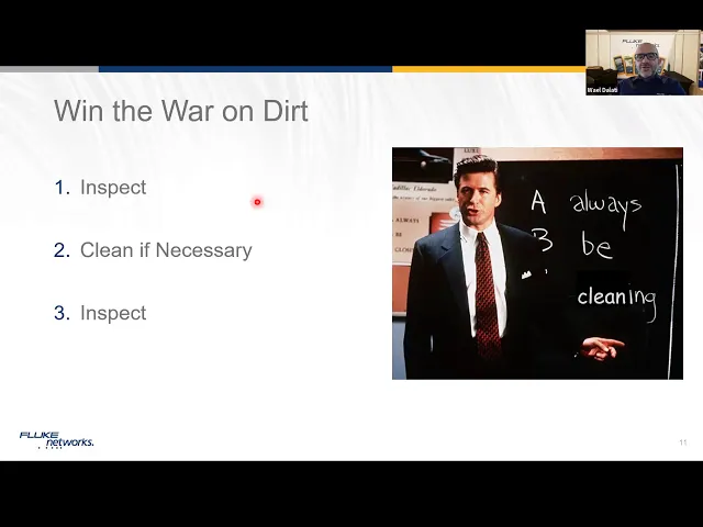
my connection or my or added values or added losses in my links that is dangerous so keep an eye on that as well so what we always recommend the rule of Thumb the three rules for fiber inspect before you do anything in fiber inspect clean if necessary then inspect again make sure if i am clean now i'm higher if my connectors are clean that means i can move on i can start connecting the tester to my cabling or connecting the active equipment to my cabling system because that would Be my peace of mind and we've
seen a best practice that some of the uh data center owners of some in the high in the dense telecom rooms in order to avoid missing cleaning fiber cabling they are putting velcro to the uh click cleaners in the cabinets so that they can attach them so technicians in the field Will not forget that and will not say oops i forgot to bring with me the cleaning kit no it's don't need to worry about it it's there in the lag if that is over that is finished open the second right get it from the second
right get it from the third there's no excuse not to clean your fiber cabling system before you do anything else so for that brings me In the first poll uh for you guys to help me and help uh you also with some information to share across us so hosts if you don't mind to start the first poll please so the first poll is talking about which fiber testing method do you use in your project is it a fiber inspection only do you use power loss optical loss test sets do you use otdr do you use
a mix and match between Otdr and optical loss set set and something that we wanted to do to ask like yeah my installation is good i trust my installation so i don't need to test and that could be also another behavior we've seen it in some areas in the in the business so we wanted to make sure that we see the alignment together around it and see how you believe in doing it and how you're doing it in your Field as well so i think we we can share the results of the poll if you
don't mind gentlemen so majority of the people i would say 50 of the people uh have believed in or are doing a combination of uh otdr and uh optical loss sets which is good so at least you do you do that in mixing of uh both components uh some people are using otdr and some others are using the power loss Which is also the purpose of this discussion today to look at what are the components and why we use that and why we use not that so thank you for that we can close the uh
so looking at fiber so we are looking at fiber from a technical uh definition from the tia defining what is tier one and what is tier two in The fiber testing so the the tia have defined a tier one testing which they call it a required parameter and we covered that in our certifiber pro as an olps platform so it's often referred as olts it's using a power source and a power meter so we start with one side of the link and we we inject the light and we measure the loss of the light And
in the total loss at the end of the link and for that one we can support up to 12 kilometers in multimode and up to 130 kilometer in single mode now in tier 2 testing which is a recommendation uh by the tia it often talk about otdr which is the optical time domain reflectometer and before the otdr is good and helpful to help us look at the length of the fiber and Identify the different components of our fiber from splice could be the connector could be a bend or break on the cable and mostly the
otdr is being used from one direction so i use it from the beginning of the link and i shoot my test across so you don't need two directions uh two equipments on two directions on two sides of the link But we need also you will see it later on that we need and uh to move the otdr to our other side so we need to test otdr in two sites and we have defined what we call smart loop system and otdr measurement can go for multimode up to 40 kilometers and in single mode up to
130 kilometer so let's explore a little bit about what do we mean about tier one testing So tier one testing it's actually the what we see today in every uh discussion that applications are becoming more and more demanding on the bandwidth in our links so the slow application the first application of yesterday became slow today and this law of today will become will this this fast of today will become slow for tomorrow all that have a major impact on What we do on our fiber links and how is our link capable to carry this application
so the same application you see here the 100 gigabit depending on the application depending on the platform it becomes even tighter and tighter if you hear from the guys of cisco they talk about 40 gigabit in 1.5 db loss and that's a pretty tight loss on your Link and there's no joke about it you need to make sure that your cabling system is perfect so tight budget means that we need to know how many connectors i'm putting on my links what is their performance and how is my workmanship and how clean is my system before
i connect any applications to it and we look at it like is fiber easy to to To understand like copper the the question is actually no because copper has been a lot easier to to define cabling standard with the applications and mixing and matching the applications to the category of cabling so there was always been always a match between the application and the cabling standards unlike the fiber fiber has been scattered between the Cabling standards and what we call the application standard and what we call that this mismatch is causing a lot of distraction in
the market where which one do i use now do i use the application standard or do i use the cabling standard and for some people they say you know what i'm gonna use somewhere in between those two i'm gonna work out on those Uh middlemen in the middle and i call it a custom limit where i define what i need to work what is best for my business and define that best for the business in my testing limits so that's why we see now a new trend in the custom limits and we've seen some vendors
also in the market some cable manufacturers calling to test according to a custom limit not according to cabling Limit or application standards because that's how probably the future is going to take us there so the three types of limits that we observe in the market today are the international standards where they are tia or iso limits we see they are working on the number of connectors and the fiber length while the ieee which is an application Standard focuses more on what do i need to run the application how many db do i need to run
my application and when it comes to the last one as a custom limit like what we said in the previous slide it's a mix and match between both components so we need to define what we need to do to make that system work in between the Cabling standard and the application standards so a little bit of brief about the development of the tia where the these things were defined in 2018 for some of the people uh they know it some of them probably might not be following those updates but the idea here is to show
you that tia over the years has started to time it up The limits of the uh components that they wanted to test so they tighten up the loss for db per kilometer from 3.5 to 3 db the mating of the first and the last connectors from 0.75 db to 0.5 db so that means there is changes in the indie standards but is that enough probably not and that's why we always ask you and ask the Technicians and the project managers in the field please make sure before you start testing in the field make sure that
your equipment is upgraded to the latest firmware because the latest firmware always carries the latest updates of the standard so if there's any changes between the previous firmware and the current firmware and you are not aware of that you might shoot some Results which might not be as actual to the current standard vision or version so please make sure that you follow that in the right way so let's take an example of a link how do we compare that link of a 500 meter between a tia limit and an ieee limit so in that 500
meter the ieee tells me to run 100 giga 100 gigabit base dr i need 3 db While if i look at this budget of this link i'm having 500 meter link into one dbs single mode is 0.5 db i'm having two connectors i need 0.75 per connector that means i need 1.5 db so the total loss budget that i have as calculated budget is 2 db now let's look at what would be the result of the tester that we induced in that cabling and we got a result of 2.6 upon 6 db Now what would
be the question here will it pass in tia certainly no because cia said my budget is 2db my link is 2.6 db i cannot pass this link i receive a fail but for the ieee like yeah that link works i'm fine with it i can deal with it the application the 100 gigabit will work perfectly on the cable now which one to take and that's where The dilemma of the cabling in fiber optics which one to choose and that's the awareness of the link that we're testing versus the application that we're going on we need
to have a harmony in between those details and that's why the need for custom limits if i do the same if i add more connectors on the link and the total link remained 500 meter But i added multiple connectors let's say attaching between the patch panels and the racks and the data center connected to connected connected to connect and then what happens next yeah i'm probably on 10 gigabit things were working good but if i move now to the budget of what i need for the 100 gigabit i'm having 500 meters again 0.5 db but
now i have 6 connected To account 4 in my budget calculation i will need 5 db as a total calculated budget while still the ieee requires 3db now my tester tells me i get a 4 db loss what does that mean does it mean a pass on tia yes it means a pass in tie i'm below the budget that means ti tells me good job you can work according to gia but can this application work in ieee then certainly no For that reason all those components and all this pressure and stress on the links have
taken hard discussions in multiple areas and particularly in multi-mode because most of the current installations in data centers and in enterprises are in multimode so tightening the application limits means that we need to tighten up also the techniques of measurement hence the launch in 2010 For the insert flux measurement where we needed to have a technique to tighten up the belt let's say on the measurement of the multi-mode cabling and to make sure that the variation of the results if we don't use a source which is in circuit flux compliant and a code a test
reference code that is instruct flux compliant We will lose potential accuracy in our measurement and we have a variance in our testing that could go up to 60 percent so you could you could get a failing pass or a failing a passing fail and this could lead to a disaster so we needed to have a system that gets the right measurement on our uh cup on our fiber cabling In los tess and what's the reason behind it if you look at the historical side of the measurement of the fiber cabling we used to use uh
more of overfilled launch condition so we overfill the core with led and then we shoot into the core and we shoot into the cable and that leads that the light can enter not only inside the core but Enter also in the claddic and that could allow some lights to jump from cladding to core and some misalignment and at the end it leads to inaccurate results so the idea of having in search flux is to focus the light and make it right inside the core of the 50 micron because nowadays we don't use any more 62.5
we're using 50 micron and we need To really go into the core of the 50 micron are we getting the right transmission are we getting the light getting right inside that 50 core and we should not go into a small sources like the vexilar testing because we don't only look at the total core we look at the part of the core which makes also our measurement Accuracy goes along so we need the insert flux condition to work perfectly again application limits becoming tighter and tighter so we need to get accurate testing to get things right
so when we look at it even we look at a lot of applications coming up today high speed applications moving more from multiple Fibers to run an applications to a two core applications like the wideband multimode fiber so we're looking at 40 gigabit into core that means we need to make sure that our cabling is capable of handling that and hence the requirement for folio and 405 to run those applications because of the model bandwidth that it can deal with so we need to make sure that Our testers can test accurate stuff and as well
as the cabling that is being installed can handle this any piece of wrong connection bad dirt bad splice would lead to that application not working on our fiber networks so let's go to that a little bit exercise which i like to to to set up a discussion around it in the next comic slice but let's see if i have a pet at home if i have a dog If i have a cat if i have anything at home if i need to measure that thing would you think that the dog if you tell him come
to the scale and stand on the scale to measure your weight would you think the dog or the cat will listen to you definitely no it would be like they would look like no no what are you talking about what is my i need to play i need to do something else So the best way to do it is to actually start with what you call it a reference so you stand on a scale by yourself you reference yourself then you know your weight then you carry the pet with you and then you look at
the weight and you see the new measurement of the scale and the actual weight of that fat that you have would be the negation Between your total weight with the pet minus your weight so you get your lovely pet weight so let's look at this table so if i measure the dog i am getting the total weight of my dog to be let's say 36k my cat would be 3k but if i try to play with the canary here and i get the canary and i stand on the way on the skin i see my
weight Going one kilo down and like huh i'm supposed to at least stay with my weight or a little bit more but why do i go down what's going on what what could have gone wrong here and this is why we see something very similar to that into our fiber cabling system because normally if i have a very high loss i know my cabling is not working But if my loss is very small and the deviation is small i'm at the very thin line of having an application to pass or fade and it's even in
a 1 db range so what to do now so how do i deal with it and that's the purpose of my next poll question gents if you don't mind uh to help me with the next fall question so the next poll question is how often Do you set a reference in fiber optic measurement so we we've seen people in the field carrying loss measurements light source powered meter or optical loss test sets and we ask them how often do you do that and we get different responses and i wanted to to also have that conversation
with you uh ladies and gentlemen to understand the importance of the Reference because as we tighten up our limits doing things right becomes even more important than ever before so as we speak the responses are coming in and i repeat if anybody has any questions during this presentation please use the q a tab to to have our colleagues answering you we have jim davis also from our Headquarters joining us he's our marketing engineer behind lots of uh videos and documentation that you see on the website so welcome jim as well uh it's too early for
you on the everett side i think but welcome on board and uh i think we're good with the poll now chance so can we share that please so we see some responses that comes With that i need to do my poll i need to do my uh referencing at every start of the project that means that counted for 44 percent uh some people said i do it with every test which is also a big number that we will explain uh that part multiple times a day which is okay not not bad and Once a day
also depends on what you do once a week or i don't need to set a reference my tester is good so going back to our topic why do we need a reference remember the story of the dog and the story of the weight setting the reference is pretty much essential we need to set things right in our cabling system so the standard requires and guide and Put us into a guidance it's not because fluke want to do it or x or y or z is actually the standard the standard becomes more strict about what is
needed to be done and what do we need to do in setting our or preparing our testing for fiber optics and particularly in optical loss measurement so if i do read the two chords and that's why this slide Is purely focusing on two lines the standard requirement you need to use a what we call a one jumper method a one chord method and we need to use test reference court and the test reference code are the by definition not the standard patch code that you bring out of your installs in your in your site and
you open the box oh yeah i have i have 300 500 fiber patch code i will pick up two and we'll start testing with Those two they are not enabled and they are not made for that purpose they are made for application to run they are made to for the system to run but for testing you need particular and special grade of connectors on those codes and the quality of that codes to be to a certain level that you don't compensate or you don't take the results in a different Direction for that reason again i'm
not gonna go into deep details because that would be a topic for our uh in-depth fiber half day session that we will do in the next couple of weeks but the purpose here is to share with you that the standard has defined that the chords needs to be perfectly made and the loss of the multi-mode the connected loss of the multi-mode is 0.1 db or less And on the single mode is 0.2 db or less and that's the mating calculation that needs to be done when we made a test reference code connector with a normal
connector in your patch panel that could be the mating of those two has been defined to be better than 0.3 db on a multi-mode and better than 0.5 db on a single mod link so test reference quotes Are mandated and are needed to be done so if we look at what we used to see back in the days when when you use a normal code when i need to do a calculation i used to add per connection per adapter 0.75 db so in this link i have two adapters and a link of a cable that
is 3.5 db and 0.75 at each Connector to calculate my loss is simply adding those two connectors here and maybe 100 meters one kilometer whatever the length into 3.5 db per kilometer and i get my lost budget before i start testing so that for many that's used to be calculated by hand or the tester will do it to you so back in the old standard the mating of the connectors Was 0.75 standard but according to the new limits the standards has changed those matings so the matings has started with the latest references to be between
the first connector and the last connector is 0.5 db remember my discussion on the tia updates back and then back in 2018 3 db per kilometer so that's how we do the calculation again 0.5 plus 0.5 plus the length of that Cable into 3 db per kilometer i calculate my loss budget now what if i have more connectors on the link what do i do and how do i calculate my length so i do look at my connector the first connector and the last again according to tia is 0.5 db plus the calculation of how
many connectors i get the loss budget now if i have the right things Done in the reference i can assure that this calcul that the measurement of that link that i will do at the end will be correct and not something that will overshoot so for that reason referencing the tester is very important and what we saw from some of you guys setting the reference multiple times a day is needed yes because i need to make sure that my tester and My remote my source and my meter are in synchronization they understand each other they
know what is the power injected by this source and measured here so they set the zero as we said in the uh measurement so they know from where i should start and when anything comes on top of that anything i add is actually the loss and that's Why people who are doing this kind of reference adding one jumper or one uh adapter or two adapter you're not getting yourself a help you're putting a two code method or the three jumper method which leads us to to have a different results than what we intended to do
there are specific cases where you need To have two code method or three code method but those are very specific on a day-to-day enterprise cabling we will need to have a one-jumper method and that's why you see our lovely seizure saying yes that's the way we need it and that's the way we need it and we will work on it in the field so please look at the reference as a first and key objective in that one now The question comes how often do i need to set the reference some of you have said multiple
times during the day i will come to it but some of you have said at the start of each project if i start up a project and my project lasts multiple days meaning i will test i will set the reference today and i keep the reference for the next coming couple of days using the same reference I'm disconnecting my tester removing the chords adding the chords removing the chords adding the chords and coming to borrow after tomorrow after tomorrow and i'm still using my same reference that i did three four days back is that the
correct way certainly no because when we set the reference we set the reference on the mating of the source here with the code with the test reference code and That code where the moment we remove that one from the tester means that i need to do another reference even if it is by mistake i need to re-reference it again because the mating here condition has changed at the source at the meter it's fine but at the source is something that we should not allow to move to happen so that's why The correct methodology of doing
a referencing is to do it probably at least once a day or multiple times a day if i am going to keep my tester away from testing for a couple of hours and i'm probably need to disconnect my tester so how to set the reference usually the technique that we coach our uh engineers and technician in the field you need to do that kind of connection Connect this the red to the the red type the right side of the patch code or the test reference cords to our source and then connect the black one to
the meter on the other end and similarly the red on the test reference code on the other side to the meter on the main machine so to tell our machine has two sources and two meters that's why we can test two cores at the same time and hence we Are having a reference for two chords at the same time now so we start the reference we save the results and now we disconnect we get another code the complementing code of the uh test reference code and now i need to check are these chords good or
not i need to connect them together and start testing those reference scores are they good Uh can i trust using them to test my link will the mating or the test of those codes will be in an acceptable zone to get my results correct at the field and these are the areas and the limits that the standards have defined and pretty much defined the results will come in front of you of the tester and boom done now If i ask the question do you remember what i was talking about in the past couple of slides
i think you know because we we always tend to forget some of the areas where what do i do now and put the reference do i do the right way did i put the right direction of the code or no what do i do i forget what what the guys fluke told me what i forgot what i learned from my cctt And then you need to go and call and lose time so and sometimes people don't do that they go on and they continue so for that reason we always ask do you expect everyone to
remember everything about it certainly no but don't worry the fluke networks we get you covered we support you and we help you because we have the wizard Available at every time you want it on the tester it's there on the main screen of the tester and the wizard takes you step by step what do you need to do which color of the test reference code you connect where do you want to connect how do you connect all the way up to the testing the reference codes and making sure that they are also good for that
reason we do that for you and we store those results as a tlc to You in our results and when you download them into link where pc or upload them into linkware live you will be able to see those things that i've done my trcs what are the length and what is the date that has been done and what is the limit it's the rc limit now if i look at the the following lines i see that i see some of those Test results done and they are within the same day which is good let
me see oh it's 1 13 p.m what time was the reference 10 52 a.m looks like i'm in good shape because my reference considering and hoping that nobody had removed the code from the source and i can look at those results that they are genuine results following that the Reference was done correctly on every also test that we have we can jump and see what is inside i see that i'm using a one jumper method here i can see that what is the length of the reference chord and if i have any negative number on
my test reference scores that means my chords are becoming waste and not helping me at all i need to throw them away and i need to Replace them as soon as possible so the wizard is your key the wizard is there and we're proud to say that we are the only company who can do that and help you with setting up the right reference without losing time without doing test results doing tests and failing things that you don't want to fail in the field now going into the second part uh the second tier tier two
of otdr so otdr has been for some time In the old days used by the uh telco operators and for the very long haul cabling and it's been there for for many many many years but we've seen the introduction of otdr into the enterprise market because there was a need for it and because of also it was the application speed limit become an obsession from some and we need to get and make sure That we measure all the components of my link to the best i can okay so that i eliminate any possible risks in
my link so if i have a dirty connector or a bad connector i need to identify it i need to fix it if i have a bad splice i need to fix that as well so what does the otdr do in in short so it sends a light a pulse uh out of the source it Checks the reflected light that comes into the uh otdr port so it is a bi-directional port so it can send the light and sense the lights again and the further the light goes the more i know about the length so
it's about time and the the distance of the light the further the light goes also i can check the fiber loss and when light has a connection i can Get a different type of light that the otdr will detect oh there's a connector here there's a splice here there is a break here and all of those details will be represented now the representation is something that we will discuss also in the next coming slides so the otdr technologies focus on the rail light scattering which is mainly the the loss and the festival connect reflection which
Looks at the connectors and there's any brakes in the cable so in short for people who are used to see otdr results that's the common screen that we get on an otdr we see the backscatter which is the drop of the light from the start of the link all the way till the end and we measure the loss across the total cable Now when we look at those spikes what are they those spikes for us as we call them reflectance and reflectance is usually a way or an air gap that happens in the fiber cable
that we are running so if i have any bulb of air or any air space in the cable could be from a splice a bed splice could be from a connector I will have air coming in between those connections or those fiber links and then light will come back and tells the otdr that those things i cannot see much similar to what we see in this picture we see the restaurant and but what i see on the right restaurant is not only a clear view of the person inside but i also see The building i
see a car here i see some details which are not good to eliminate those details i need to probably come closer meaning eliminate the air gaps between the objectives so that's why we have those reflective events happening when we have most most of the time a connector and it's beginning of the connector we see it and we analyzed and we understand That these are potential connectors and how do i measure the loss of that connection or the reflectance is the negation of the loss that is in the beginning of the reflectance and at the end
of the reflectance i measure the loss and i know the connector loss so this is what we call a reflective events and when it comes to non-reflective events Which is happening from a splice or could be from an apc connector or angle polish connector because they are meant to be manufactured with an excellent reflectance so they show me a drop rather than a spike in my link i think enough technical questions and it's ready for a third poll uh chance if you launch the third poll for Our audience please so how do you test with
an otdr testing with otdr has some techniques and some people know it some people don't know it and some people just do it because somebody told them to do it that way and when i look at it from one perspective is that do you use patch code with it you use a Long cable what we call the drum or the launch cable at the beginning only or do you use a launch cable in the beginning and another drum at the end of the cable there are different techniques of the testing and let's hear from you
guys and we will share with you the actual standard the guidelines on what do we need to do in those kind of things So as we as we get more results i think we have a bit of a balance between the result of the three types i think there's one leading which is the correct one i will not talk about it until we get the click of the minute yeah so we can stop uh the the if you don't mind as we see the the guidance when we talk about it it's about Can i use
three meter or five meter code we will see that in the next slide why not we don't recommend that and we don't like it and not us it's the otdr don't like it as the technology cannot digest small links do i need a drum at the beginning of the cable yes do i need to have a drum at the end of the cable yes can i deal with it without dom at the end of the cable no Wait for it you will see it in the next coming slice so if i have a launch cable
with a patch cord what do we see here the light comes out from the otdr so the the time for the otdr to start stabilizing the light becomes too short to see the first connector and the idea here that we see from what we get on our event map which is the specialty of loop networks that we Make life easy for you to see it it's not only graphs and graphs and graphs and spending hours to understand them we tell you there's something really strange here i see a hidden connection after 2 meter of my
otdr and then i see a link of 51 meter so for me this kind of link in is not showing me good thing because first thing i cannot see the first connector of my link Second i cannot see the end connector of my link and i cannot know the overall loss of my link so multiple mistakes are happening here because of using only patch code at the beginning and nothing at the end so what do we do here so what do we do we need officially by the standard to have a cable a drum we
call it drum you call it launch cable A length of cable that you start the con the the link with attaching it to the otdr and attaching it to the first connector of the link that's where the grey area here and the second drum or the second tail comes at the end of the link where you can see the second one the intention of those launch and tail is to allow us to visualize the loss and the first connector So we see the spike or the reflectance of the first connector so we can measure the
loss of that connector here and at the last connector i could see another reflectance and i know the loss of the last connector all that comes in the benefit of the link so we need to make sure that we get this right if i don't have a launch and the tail cable i'm going really wrong and for that reason you Know as we said and before in the uh loss the trcs the test reference codes there's a lifetime for those connections and to prolong the lifespan of the connector of the otdr we need to use
what we call the sacrificial code that we enter one time here in the otdr and you could use that for a thousand 750 connections and use it and then you prolong the life of the otdr port So why do we need also another discussion why do i need a bi-directional test because sometimes if i go in the fiber from one direction i see some data if i look at the splice here the splice could give me if it is good it gives me the right result which is the right loss but sometimes i might get
a long data here i might get a false loss or a false fail A false gain so what do i do here how do i know that my connection is good for that reason the standards also recommends and ask people not to use only one direction of the otdr so you need to have a lunch and tail at the beginning of the end that's for sure but don't test only in one direction you need to test in the other direction for that reason we need to understand The mismatch in the backscatter from each direction to
know if that link here showing me a loss or a fail with 0.8 db and a pass was minus 0.37 db which one is correct here the correct is actually when i do the averaging of those two measurement and then i come with a correct result of the loss of each and every component of my link For that reason the standards required and ask us to go that direction so what do we see on the otdr we see multiple things on the otdr i will go through it very quickly we see them from a good
connector to a bad connector a good splice to a bad splice launch condition a hidden event bend splitters endofiber all those to visualize and Help you see things in the right way let's see another example here quickly i have this link which shows me a reflectance here a reflection which goes into point 14 db and then a certain reasonable acceptable reflectance but let's look at the second one second pulse here which shows me a lot bigger than the first one what are we Having here i'm seeing here a high loss and a bad deflectance which
leads to me that there's something really wrong at this connector that i need now to go and fix that connector because of the both the loss and the bad reflectance so the event map help us look at things not only in traces because when we look at the traces traces sometimes could be difficult to Decipher unless we have really good experience into it but with our optifiber pro otdr we can take that information instead of deciphering this into a easy way to look at it and tell you that it's a band that is abandoned the
cable and the technical requirement here is like you see these three wavelengths showing me different information From experience i will know that when i see those kind of variation in multiple wavelength that means a question mark am i having a heavy band here so that's an example of how to rescue yourself with an easy visual interface rather than deciphering hours of understanding what could that mean that leads me to the last poll uh that would be a quick one because it Will help us close the the the last part of this uh presentation because we
wanted to know how many of you are using bi-directional otdr how many of you hear from the consultant or here from the end user or you as an organization believe that by direction odr is required so do you do it some people say never I've never done it some people i know i don't know when to use it or i've been requested to do it or i do it on every project i know for a fact large project class large big projects in our region with large international consultants they do ask for bi-directional otd artistic
[Music] so as we as we fill in this information So bi-directional testing i wanted to share with you quickly what we do in the in the field so i think we should be getting ready to have the answers so i think majority of the people in the audience here have answered uh yes we can end the qualities so i answered on every project they do by direction testing which is a big thumbs up well done i think that that is a very Correct uh answer uh when requested to do it well sometimes people want to
go quite quick they do one side but remember the standard asks for bi-directional testing it's not a choice that you have to do or if luke asked for it or a brand a or b or c did ask for it it is a must to be done it's a standard requirement so what do we do here in the what if i'm Doing bi-directional test what is to be done more details will come in our next month uh in-depth uh overview on the fiber but i wanted to share with you quickly how people do it so
if i have a bi-directional testing the non-standard way because you will see why i'll start my first test i will get my direction of that link of 300 meter i Test from here to here yeah perfect condition the launch is here the tail is here and the first test is okay now the standard tells you because of remember the mating between the connectors of the launch cable we should not play with that mating that means i need to take that otdr now after the first test to the other end put it at the other end
and start Testing backward and then when i do that i need to move the otg out to the other side so it's like running a quick marathon between the two sides and if you have a long distance that would be a disaster so what people usually do they follow this procedure they test the first link and they test all those links and then they move to the other side and they test so let's follow this practice Here so they are literally not following what the standard requires to actually measure do you need the first and
last connection you need to take the otdr to the second end they start going one link after the other one link after the other in in one end and once this is done they take the otdr to the other end and we start testing again from that other end Is this correct according to standards no do all of us know about it i would say majority no but that's the reason why we're coming here to tell you watch out there are some practices that we think we're doing it right but they are not really right
for that one for that side fluke networks have introduced the specialty smart loop which is our Trademark and our invention in the otdr to do a bi-directional test without moving the otdr away from the telecom room that we are in so it is easy to mone to to configure it on the otdr you just select smart loop or tdr and you will let's say you have a link that you have your otdr you have your lunch and you have a link And at the end of the link normally you put a tail fiber but what
we ask you now to connect the table from one core to the second code in your link because in enterprise we use normally duplex cabling so connect the second point of the launch cable to the second core and add an additional drum of cable at the end of fiber b so we Have fiber a and fiber b this is very helpful in many areas and imagine you have to test a cable that ends up in an antenna or end up into a very delicate environment or let's say in an oil rig are you going to
fly the otdr to the oil rig and come back and go and come back so we're trying to help in finding an easier way and that means that what we're doing now we start our test in fiber from one direction so i Shoot my light inside the fiber a it goes in the fiber a goes into the drum and goes back to fiber b and goes out from here so i test one direction of that cable that means i move now the otdr to the second cable as you see i'm still in the telecom room
i did not change anything in that side and the side of the middle drum and i shoot the light from fiber b so it Goes from the other side of fiber b to the drum and goes back again to fiber a that means on each and every fiber i've done the two direction measurement so the good thing is that the otdr will automatically do the calculation and will help you split the results and get you the bi-directional average on your screen without even moving out Of your otdr so how does that work so the otdr
will take that result that comes in and starts slicing it into two fibers so fiber a fiber b so that's from one direction and then start taking that fiber into a more graphical user interface on the event map and we see now that my fiber is 165 167 feet And that's the loss and that's you can see here three tabs one two end average i can look at my fiber if i click on it i can see different directions so that's my results of the first fiber fiber a and my results on fiber b and
with save button all is saved with two tests remember i've done two clicks on two tests i've got six results two directions for each Core and one average so how is that happening if i have the result i see direction one at this side i see direction two at this side over the same cable which i have already tested and it ends up with the directional with the average bi-directional average so you see here the connector is the same as this connector is the same as this connector so Whichever direction i'm having i will be
able to see my link and that happens in two clicks on the cable and all what you need extra is one extra gram and that's it no extra payment no extra uh membership to subscribe to no extra license no extra anything just one extra drum and you're set to go so for that reason i would set my Takeaway for the for this session remember the beginning and it's always been the the paint inspector connector please inspect your connector don't rely that the connectors are clean you might have come last month and yeah i cleaned my
cables last month but yeah last month till today is the 30 days we don't know what has happened clean if necessary repeat to clean inspect and clean is Until you get a clean connector tier the one loss testing gets you the uh temperature of the light goes out at the end of the tunnel and tells you how much that light to allow you to see if that application will work and don't forget that test reference code are important you need to set the reference with a test reference code And don't forget that it is a
one jumper method that needs to be done tier two otdr troubleshooting is great to find the end of the fiber like to find bends breaks any problems on my cable find the loss of components of my link maybe that connector is not good let me fix that i can get a better loss overall so i can do my troubleshooting on the otdr and then come back to tier one And retest after i fix and then i get things right so keep doing things right please so again from another terminology how either look at it we
saw about tier 1 tier 2 how either look at it again light source power meter or lts optical loss test sets with one jumper method with otdr with launch and tail and don't forget we can do the smart Loop and i wanted to kind of wrap up my slides with the fiber for all promo we've been running this fiber for all over the past couple of months and it's it's important to realize that this promo is reaching to an end soon we have done a lot of uh activity around it our prices have been slashed
and reduced heavily for this Promo if you have any requirement or any need for any fiber tester or a kit with fiber please reach out to us we are here to help you to support you in this product time is running out soon so we hope to to help you more with those before that uh time ends up and thank you for your attendance i think i i jumped two minutes above my time so I'm sorry chance but if you have any questions please keep on throwing some questions i have not seen how many questions
is happening in the background and uh mike's off mike's uh unmuted for salah and jim if you need to ask any questions please so yeah thanks thanks well uh yeah i think most of the questions were answered uh having jim davis with us uh yeah it Helped a lot but yeah we've been very lucky today thanks james for your early comment i really really appreciate it no thank you that was a very good presentation i enjoyed it and it was factually very accurate very good thanks thanks for the for the one who wrote it by
the way the the one who wrote that presentation is jim so thanks for you james as well Yeah thank you so if if we're not having any more questions uh if not have any critical uh point that probably jim want to to close with it during this slide uh or during this session please if you have any questions there is still one question or it was asked already similar so if a consultant asked to for the reflective events on the end connector But you have only one launch cord is it an okay to test from
both ends but only one direction so we they're asking is it correct or not so it seems they only have one launch court still the consultant asks for the reflective events on the end connectors maybe maybe jim go ahead sure if you made a good point about needing to use A launch and a tail or a receive fiber to be able to measure those connectors now you also did a good job of showing the importance of bi-directional averaging that's just the mechanics of the otdr as we go from one fiber type to another we need
to measure the loss in both directions to get an accurate value so if you only have a launch fiber you're going to measure the you're not going to measure the loss Of the last connection and if you take that launch fiber to the far end and you test it the other way you'll only have one direction of loss for that last connector so you won't be able to make an accurate measurement of the loss in both directions for those two connectors to do that you need to use both a launch and a tail or receive
fiber or receive Drone yeah that's a valid point so that's why we we need to make sure that uh to get a second drum or the uh or the end cable or an n-drum or tail it's not the investment it's not a big investment it's not about the investment it's about the accuracy of the results that we have and to get things right i think we've stressed a lot into it and we keep on Talking about it still till the standard stays different but we're following strictly the standard and standard have showed this is the
right way and measurement tells exactly the same another question and maybe it's a repetition you can pull that slide with the overview so someone asked to tie a cable fiber optic cable between Two passive racks only 250 meters from each other is the light source power meter enough for certification or you need also otdr this is one of those questions where we like to say it depends on the contract and what the end user is asking if you are in a data center and your intention is to transmit 400 gigabit ethernet You may have an
interest in knowing the reflectance of those connectors which would require an otdr test but if you are just required to do the loss testing a light source and a power meter as well mentioned several times is the tier one or the basic requirement for lost testing yeah great someone asks or says the prices of our machines are pretty high how can we get reasonable Price i would like to answer myself so while mentioned we have a promo running nevertheless we believe that by using our machines you avoid mistakes you maybe win faster projects or can
make more profit by using our machine so we believe it's like a cash machine it doesn't cost you it will make you a lot of money From whether you want to add something or seller yeah i want to add one thing also in the in the uh smart loop on particular some people talk particularly they talk about our price of otdr but yeah i said it's our price of 40dr is fixed we don't add or charge excess for any feature that you want for some other brands if you need to say i need that feature
you pay a few Thousands of dollars for it to to get that feature for us we don't need anything and if you use smart loop correctly you're kind of cutting down a lot of your testing time so imagine how many hours and days you save if you have thousands of links of otdr measurement how much you save you save days and days if not weeks so we have experience in some customers that they have cut Down a single shift of a work because of the speed of smart loop so i think in one of the
slides it cuts 1 8 of the time of the testing so it's really fast you only see it when you do it and this is alone pays back in in no time your investment now what will happen if an otdr test is done without a large cable yeah eventually it's not correct so If the consultant or the manifest cable manufacturer when they look at the results they observe those results they will immediately spot on those uh mistakes and they most probably reject those results so to do things right yeah i was just going to say
there is one situation where i'm less concerned about the launch fiber And that is if my fiber is cut um if if i'm on this call and this call drops and it's an issue with the fiber i don't care about the first connector i just want to know the distance to where somebody cut my fiber but otherwise you're absolutely right we cannot see the first connector without a launch fiber and a very common problem i see with the traces that customers send us is they don't use A receive fiber and so we don't know what
that last connector what the condition is of that last connector yeah we have one question also how long does the launch and tail fiber should be well the length of the launch and the tail fiber is a function of the pulse that you're going to be using when we're configuring the otdr and our Otdr will configure itself automatically it must choose a pulse width it will choose a shorter pulse width for shorter lengths of fiber and a longer pulse width for longer lengths of fiber so in the multi-mode world where the longest piece of fiber
is only four kilometers long i wouldn't expect that you need more than a 100 meter launch fiber Now in the outside plant world where we use single mode and you may come across a large splitter a 16 or a 32 port splitter or you may have a fiber that is more than 100 kilometers long in that situation you may use a longer pulse and you want the entire pulse to fit into the launch fiber now if you are using shorter single mode lengths the 160 Meter launch fiber that we include is going to work just
fine up to a pulse width of 1000 nanoseconds and that is going to cover almost every common point-to-point link in a campus environment in a data center environment but when you start going to things like splitters on the fiber or longer lengths of fiber then you may need to use a longer fiber again it depends on the pulse width And it is a rule of thumb that the physical length of the pulse is uh the length of the pulse width divided by 10. so if you have a 300 nanosecond pulse it's about 30 meters long
if you have a 1000 nanosecond pulse it's about 100 meters long so you would want to be using a launch fiber that's longer than uh than your pulse sorry for the long answer Great so any closing word teams to uh to the audience before we wrap it up oh oh boy we're running over time but hey i'm i'm really impressed to see so many people with such interest in fiber and i'm glad that you were able to put on such a good presentation to help explain the ins and outs of working with fiber we know
that we're just going to want More yeah indeed that's that's always the question that we get we we need more in-depth so um we're preparing the background so for the people who are still there uh apart from the normal webinars that we're doing we are preparing some deep in depth so you probably need to to take a half a day with us on some time where we will talk deep deep down details into some copper or fiber And that would be quite interesting topic but requires as i said a longer time with us uh therefore
stay tuned for more information more updates about our upcoming webinars and our specialty uh technical sessions uh that will come in july so stay tuned thanks everyone for attending thanks a lot jim again big thanks uh for your the big kudos also for your attendance uh For waking up so early in these in the states and uh good luck for everyone and your return back to work and uh hopefully you stay safe stay good and good luck in your business have a great day thank you very much