Hi, welcome to the forty second module for the course, and this is the last module for this week. In this module what we are going to do is, we are going to put the whole thing in a test bench, and check that we designed earlier is correct or not. So, when you design test bench is one of the thing that we have to do is come up with what is called a test plan.
So, remember we agreed on some kind of a protocol between the machine that we design and the external world. Unless you do that we cannot expect the machine that we design to work under all possible condition So, some of the protocols that we agreed on are that, if the state machine still working, then we are not suppose to give more inputs. So, this is some protocol that we have to agree on.
And because if we do not agree on that, and then we can keep giving inputs at any point of time The other thing that we agreed on is we will give the inputs, and then we will turn on the go signal. So, that the inputs becomes table, we agreed on that. So, will have to come up with the test plan which take care of all of these things.
So, what I have done is, I have return down tentative test plan for this testing this particular design. So, the test plan is like this. I will start with resetting the chip.
So, the first thing that we need to do is reset the chip, because the chip is not reset then it is not expected to work anyway. So, once we reset the chip, we place the inputs; once the inputs are placed, we can turn on go which means from the external world point of view, there is the inputs are ready. However this does not mean that the state machine can start working.
So, it is possible that we need to wait for the state machine to finish. So, we will wait till this done signal becomes 0 for whatever reason, if done is 1 will have to wait, wait till done equal to 0 at this point we remove go. So, once you remove go the state machine will start runny; the state machine, it is starts working will have to wait again till done becomes 1.
So, that is the sixth point, we will wait till done becomes 1. And once done becomes 1, the output is ready; if the output is ready, we may have to copy it, print it, whatever at in the simulation we will go and printed when you if you actually design a chip which needs GCD, it will take the output and maybe copied locally and what not And then it is ready to go back it place the next set of inputs. So, what we are going to do is, we are going to follow this protocol will reset the chip place the inputs turn on the go signal, wait till the done signal becomes 0, because if it is not 0; it means that there is something that is happening in the chip.
And once that is over we then remove go which means this is the pulls that is given to the state machine, the pulls comes and goes the state machine will start working, and then we can do the rest of the stuff. So, this is what we are going to do in the test bench. So, what I have done is, I have already written this test bench now.
So, just the test bench the test is relatively simple to write, I have already written the test bench So, the test bench has clock reset and go which has suppose to be given as inputs to the machine that I design, and it has two inputs which has suppose to be locally generated within the test bench, there is an output that is supposed to be coming out and this is also a done signal that is out from the GCD machine itself. So, the GCD machine has clock reset go input 1, input 2 which are all going in, output and done which are coming out. And I have return a small always block which simulates the notion of a clock.
So, all this does is it makes clock equal to 0 wait for 25 units make clock equal to 1, wait for 25 units and then repeats this over and over, which means this is a clock of with 50 time units. Then this part of the code takes care of printing way forms and what not, let see whether the test plan is correct or not. So, we initially make reset equals to 1.
So, we first go and reset the chip, and we ensure that go to the go signal is 0. So, the go signal is 0 and then we wait for this has 100 means wait for 100 time units. If you go and look at the clock period, it is 50 time units.
So, we are having the reset on for two clock cycles; once the reset is gone we pull down reset So, the resetting the chip means, bring it to 1 and then bring it back to 0. So, that will reset the chip at this point all the registers will have 0, and if you remember the state register also has a reset input, it will go to 0 0 0, and 0 0 0 is first state s 0. So, this will take it to state s 0.
At this point go to is 0 which means it will loop back in state s 0 itself. Then we go and place the inputs. So, this is the second part of the test plan, place the inputs in this case I am testing the GCD of 10 and 5.
So, I am giving 10 and 5, I am and I am giving two cycles a study value. So for two cycles 10 and 5 will be placed studiedly at the input of the data path. Then I make go to equal to 1.
So, that is the third step turn on go. The fourth step says wait till done equal to 0. So, wait till done equal to 0 is equivalent to while done equal to 1 wait.
So, if you have to wait till some condition happens, then is as good as saying while the negation of the condition is happening wait. So, this is checking while done t equals 1 then wait, it means we are expecting. So, if you are and state s 0.
So, whatever reason the done signal is not 1, then there is some faulty condition. So, act the s 0 state, I think we initialize done to 1, let me go check in the s 0 state. So, it looks like, I am not may done equal to 1 in the start state in the s 0 state.
So, I will make that 1. Save it, if I go back to the controller now, I go back to the controller. So, the controller is going to wait when the done signal is 1, which means for whatever reason the state s naught, if you are not there I will wait, till s naught is till we are an s naught state.
And then when we remove the go to signal. So, if we remove the go to signal, go to of 1; at this point when go to equal to 0, the state machine starts working. So, at this point the state machines starts working, and the state machine is suppose to a change a lot of things, and then finally bring it to the done state at the, when it goes to the final thing again done becomes 1.
So, will have to keep waiting in the test bench till the done becomes one. So, while done t is not equal to 1, this point we are saying that if it is not equal to 1, then the state machine is still working. So, I will have to wait.
And when the exit this while loop, we are ready to print out the output. So, when exit the while loop we know that done is actually equal to 1, at this point the output is correct. So, this is the basic test bench plan.
So, again let us go and look at the review the plan, reset the chip place the inputs turn on go, wait till done becomes, because if done is not equal to 0 there is something wrong, wait till done become 0; once done become 0 you remove the go signal, FSM will actually start working. And then we wait till done equal to 1, because at this point the state machine is working, now we have to wait for done becoming 1. And when you come out of that output is ready, and we can print it or view it or whatever.
And what that enables has to do is another interesting thing, once output is ready we can actually go back and place the next set of inputs. So, let me first try this, I will run this and try. So, it is opening a way form.
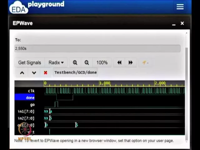
Let me get the appropriate signals. In the GCD machine I have I need clock reset, the two inputs go done and the output. So, these are all the things that my GCD machine has… So, I select all of them.
And let us look at it. So, clock seems to be something that is periodic, and let me rearrange the signals, so that it will make some logical sense. So, I am going to bring the reset to the very top, and done should go to somewhere in the bottom the two inputs.
So, this is logically sequence now. So, according to the test plan, I will initially bring reset the chip which means I reset the chip and i. So, I put it at 1 and I bring it down to 0.
So, the reset part of the test plan is correct. Once the reset is done I am going to place the inputs. So, in this case I am placing the input a, and five.
So, a is for 10, and b is for 5. So, I can convert the radix. So, it seems to be only hex and binary.
So, its leave it at x itself. So, this is 10 and this is 5. So, we have 10 and 5, once these are ready I am making go equal to 1.
So, go becomes 1 and when go becomes 1 it checking what the done signal is, the done signal happens to go to 0. So, also becomes 0. So, go becomes 0 at this point the state machine is beginning to work.
The state machine is doing its work for whatever number of cycles, and it is ready to give the output at that point done becomes 1 and when done becomes 1, you can see that the output that you are suppose to get is 5. So, done becomes 1 and this output becomes 5. So, looks like it is ok so far.
So, I am go to try another set of inputs. So, I can actually go and place another set of inputs now. What I will do is, I will copy from here with the new set of inputs.
So, I am, let say I am going to put, let me put this, so 243 minus 144. So, I am going to put some other numbers 243 and 144. So, in this case, I think it is the both are divisible by 3.
So, let see what the GCD is suppose to be then again I save it run. So, the way form is opening up, let us get the signals once more. So, again all these signals are of interest to me, except the output enable signal.
So, let see what does happen. So, again I am go to reorder all of these. So, reset goes to the very top, go goes next, done goes to the bottom and the inputs also So, go can go down, yeah.
So, let us look at this now. So, we have the clock the reset when to 0, then we place the two inputs a and 5, we give a go, the done signal become 0 because it is not done at some point it becomes 1, which means at that point I can go and read the output, the output is 5. Once that becomes 1, the my test bench is giving the new inputs.
So, these are my new inputs, this is 243 and this is 90; 90 is 144. So, 90 in hexadecimal is 144, f 3 is 243. So, I given 243 an 90 or 144 as inputs then I again give a go, when I give a go then the done signal again is pull down to 0 by the state machine.
It is now taking more time. So, GCD of 10 comma 5 is can actually be resolve with only 1 subtraction, where as gcd of 243 and 144 cannot be resolve with 1 subtraction. So, 243 and 144 it takes a bunch of cycles, and then finally the done becomes 1 at this point the output is 9.
So in fact, if you want to do go and see the state transition itself, you can go and look at the state registers inside the controller, the controller has two states, two state registers. We can look at the just the cState which is the current state, let me append that. If you look at cState, and if you expand it you will notice that they are having some nice transitions that are display.
So, let us go and look at this. So, initially we are and let we move it to the left. So, I am I move it all the way to the left.
So, it looks like initially, the state machine is in s naught when go goes high, it goes to s 1 which is what we expected from the state diagram, then it goes to s 2, it goes to s3 So, we gave 10 and 5 as inputs, from s 3, it goes to s 4, because 10 is greater than 5, that it goes to s 6. So, at this point we have done 10 equals 10 minus 5, it again you come and check at this point 10 is equal 10 minus 5 is 5, and you are comparing you are getting GCD of 5 and 5 So, it goes to s 7 and s 7 is the final state and from there we go s naught. So, this seems to be the case for 10 and 5.
So, at this point we are giving 243 and 144 as inputs. So, 243 is greater than 144. So, 243 minus 144, that is done here.
So, 243 minus 144 is 99. So, it goes to state 4, and state 6. Then we have 99 and 144.
So, if you look at 99 and 144 then again 99 is greater than the 144. So, sorry 99 is lesser than 144. So, if 99 is lesser than 144, from this state 3, it goes to 5, because 99 is less than 144.
So, 144 minus 99 is 45. So, it goes to state 6, then you have you are comparing 99 with 45. So, from there on it continues 99 and 45 you compare, then you will compare 45, and so on So, this goes on forever till the final result comes through.
So, at the very end if you notice the final result is 9. So, 99 minus 45 is 54 sorry not 44. And if you keep repeating that eventually you will end up with 9.
So, you can see the state transitions in cState if you want. So, what we have done is in this week we have done something very, very different from the rest of the weeks. First of all there are no power point slides.
So, you have to see the video to do this things, the other thing is I am going to supply the verilog files to use, if you want to go back and change things and manipulate and so on, you are ready to do it. In fact, I designed a, what is called a mealy machine, you can go and see if it can be converted to a moore machine easily. So, my suspicion is its actually easily convertible to a moore machine, I would suggest that you go and try it take the verilog files and play with it, but what we have done is from a design problem that is specified as in algorithm, I converted that to a state diagram to the appropriate data path connected all the of them together wrote the verilog code for all of that, and took it to a stage where it can be simulated and where the results can be seen So, this quite a leap from the previous set of classes, but this is interesting and important, because this is what designers in the real world do, they have the design state machine sometimes not just one state machine, the design multiple interacting state machines which all take care of moving data from one place to the other at the right points of time to get some computation done.
So, what we will see in the next class is a minor variation of the state machine and then we will go on to an interesting topic namely pipe lining and parallelism. So, this will be the contents for we will see what it means to pipe line a circuit, what it means parallelize a circuit, and what are the design choices in doing that. But this week is suppose to give you material on state machines and you have seen that in elaborate detail, I suggest that you can take a problem on your own, and try and do something like this.
So, maybe I will pose something on the forum later which suggests the problem on which you can work on a state machine. Of course, you will also have home work problems which are all on state machine for the week 7 So, thank you very much and I will see you in the next week bye, bye.