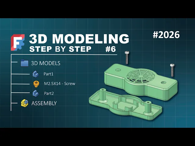
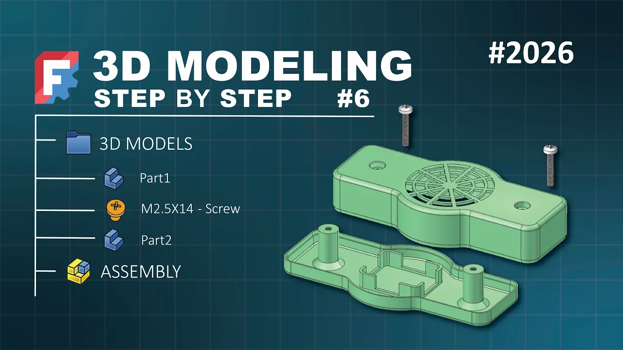
In the last videos on this channel, we designed the 3D models in the Part Design workbench. Some are a bit more complex and others not, but it was in video three that we worked with more than one body object. In this video, for this mini 3D project, we will go a bit further than that.
We won't just work with two body objects. We will also need to use an external workbench to add the other objects to the document. These will be screws.
And to assemble the parts, we will use the Assembly workbench in FreeCAD. The top part will be the first one to be designed and the bottom part will be the second one. During the modeling of the first part, we will add a screw to the document so we can better position the extrusions and holes needed to fit the screws in both parts.
Because as we can see, we don't have all the dimensions. What happens here is that each of the two parts has to be in its own body object. And because of that, when creating the document for the main 3D project, we can click on the parametric body option and that way we will get a document that already automatically contains the first body object.
Let's rename the body object to part one, go to the tree view and select the body object and press F2 and rename the body object to part one. Next, let's create a sketch on the XY plane of this part one body object. Go to the Part Design Helper features toolbar and click on new sketch command icon and select the XY plane as the attachment plane of the sketch.
We're on the Sketcher workbench as you see in the workbench selector. The best approach for this sketch is to create a complete geometry so we can use the sketch as a path for a sweep cut when creating this channel in the part. So, we can start by creating a rectangle with rounded corners.
And to do that, we have to go to the Sketcher geometries toolbar, expand rectangle tools and then select this option, centered rectangle. Click on the origin point and create a base rectangle. As you can see, we don't have rounded corners here.
And to do that, we go to the rectangle parameters on the task panel and we check rounded corners or you can use this keyboard shortcut here. And then create a base rectangle with rounded corners. Skip the tool and next select the cycle command and click on the origin point and create a base geometry.
Skip the tool, right click, and now it's time to trim some lines and some arcs in the sketch here. To do that, we go to the Sketcher tools toolbar and we select the trim tool. Now let's trim this line, this arc, this line, and this arc.
Now skip the tool, right click, and let's add fillets on the sketch here. Go to the Sketcher tools toolbar and click on fillet command icon. Now let's create a fillet between this arc and this line here.
The same thing here. And here and here. Skip the tool and now as you can see, we have 11 degrees of freedom.
To fully constrain this sketch, we can start by selecting these two vertical lines here in this way and apply an equal constraint because they have the same length. To do that, we go to the Sketcher constraints toolbar and we click on equal constraint and we have this 10 degrees of freedom. The next thing that we can do is to select the base four horizontal lines and make them equal.
So, let's go to the Sketcher constraints toolbar and click on this icon again. And now we have this. The next thing that we can do is to select these all four fillets and these one for example and constrain them to a radius of 5 mm.
To do that, we go to the Sketcher constraints toolbar again. And now expand the dimension tools and we select radius dimension. And we set 5 mm here and then we press okay.
Next, let's select the base arc here and this one and go to the dimension tools and select radius dimension and now we set 20 mm for this. And as you can see, it's not working. So, what we can do here is to for example set a distance between these two vertical lines here and distance between these horizontal lines.
For that, let's select the dimension tool and select this line here and this one and create a horizontal distance of 85 mm. And now from this line to this one here, the distance is 28 mm. And as you can see, some arcs disappeared here.
So, what we can do is to undo this operation and skip the tool and drag this line here a little bit. Okay, and increase the radius of this arc and select the dimension tool again and now select the two horizontal lines and set 28 mm of distance. One degree freedom as you can see.
Now we can select the base arc here for example and set the correct radius, which is 20 mm. And now we have a fully constrained sketch. We can close it.
And now we can use this sketch to create the first solid for the part one. To do that, let's select the sketch in the tree view and then go to the Part Design active tools, these tools here in yellow, and click on pad command icon. And as you can see here, we have a preview of the extrusion.
The length of this extrusion is 10 mm as you can see in the pad parameters. But this is not the real length of this extrusion. The real length is 15 mm.
So, change to 15 and then press okay. And here we have the first shape, the first solid for the part one. And before we add a thickness to this model, let's create a fillet feature on this face here.
To do that, let's select the face and let's go to Part Design dress-up features toolbar, these all tools here and click on fillet command icon. And change its radius to 1. 5 and then press okay.
And here we have the fillet feature. Select this bottom face and click on thickness command icon. And the size of this thickness is 1 mm.
Press okay to finish this. Now that we have the thickness feature, let's create the channel on this model. To do that, we will need a sketch so we will create a sketch on the XZ plane of the body object.
Go to the Part Design Helper features and click on new sketch command icon and then select the XZ plane as the attachment plane of the sketch. In this sketch, the first thing that we can do is to import this edge here of the 3D model into our sketch as a reference geometry. And to do that, the first thing that we have to do is to change the geometry to construction mode.
Click on this icon to do that and next go to the Sketcher tools toolbar and click on this icon here, external projection, and then click on this edge. And now we have this line here as a reference geometry. Change to normal mode and now expand rectangle tools and select rectangle, the first option.
Click on this point and create a rectangle with a width of 0. 5 mm and 1. 5 of height.
And we have a fully constrained sketch. Skip the tool and close the sketch. And now let's use this sketch here to create a channel on this model.
Let's select the sketch 001. If you want, you can rename this sketch here to profile sketch. Okay.
With the profile sketch selected, let's go to subtractive tools of Part Design, these tools here, and select subtractive pipe command icon. As you can see, the model disappeared. We only have the sketch here.
To fix this, it's very simple. The first thing that we have to do is to add the first sketch as a path for this profile sketch here. To do that, let's go to the pipe parameters, go to path to sweep along and click on object button.
And next go to the tree view, expand the pad feature tree and select this sketch here. Okay, and now press home on the keyboard. And as you can see, this is the preview of the feature.
Let's press okay. And now we have the channel as you can see. Okay, next let's create a sketch on this face here and use that sketch to create a pocket on the model.
Select the face and go to the Part Design Helper features and click on new sketch command icon. And here, what we are going to do is to create circle geometries. So, go to the Sketcher geometries toolbar and select circle.
Click on the origin point and let's create the first circle with a diameter of 32 mm and let's create another circle with a diameter of 27 mm. Another circle with a diameter of 18 mm and another circle with a diameter of 16 mm. And the last circle with a diameter of 5.
7 mm. Now let's close the sketch because it's fully constrained as you can see. Now, let's use the sketch to create a pocket.
To do that, we have to make sure that the sketch 002 is selected, and then go to subtractive tools of part design, and choose this one here, pocket tool. Okay, this is the preview, and we have 5 mm for the length of this pocket, and it's okay because the thickness of the model is 1 mm. So, we just need to press okay.
Okay, we have a problem on this pocket here. It's missing one circle. So, let's go to the tree view, expand the tree, and double click on the sketch 002, go to the sketch geometry toolbar, and select circle.
Click on the origin point, and set 25 mm for this circle, and close the sketch. And now we have this, as you can see. Next, let's select the this face here, and create a sketch on it.
Click on the new sketch command icon, and now let's select the centered rectangle tool from the rectangle tools, and click and let's click on the origin point, and set 1. 5 mm for the width, and 33 mm for the height of this rectangle. This sketch is not fully constrained.
We have two degrees of freedom here. This means that the center point of this rectangle is not constrained on this point. So, let's do that.
Let's select the decent point, and now the origin point, and let's use constraint constant. And now we have a fully constrained sketch. Let's close it.
And now let's extrude this sketch here downwards. Select the pad tool. For this extrusion, we don't need to set the length.
We just need to go to the pad parameters, in the type parameter change to up to face, and then rotate the view, and select the this face here, and then okay. The next thing to do is to create a polar array of this extrusion feature. Let's go to the tree view, and select the pad 001, and let's go to the part design transformations features toolbar, and click on this icon, polar pattern.
Change the number of occurrence to five, and then press okay. Now, what is missing on this model is to create a space for the screws, and to do that, we're going to use the fasteners workbench to add a screw object in the document. So, click on the workbench selector, and select fasteners workbench.
This is an external FreeCAD workbench, and if you don't have it installed in your FreeCAD program, you can get it using the add-on manager. As you can see, the workbench has a huge number of ready-to-use objects. We will talk more about how to use it in another video.
Our goal here is to add the screw object with this reference, and to do that, it's very easy. We can click on this icon, for example, and let's hide the part one body object, and now if we select the screw object in the tree view, and go to the property view, we have these all parameters here. And the first parameter that we have to change is the type.
Let's click on it, and scroll down to this option here. Okay, this is the correct reference. Let's close the start page, and select the object again, and go to the property view, and now as you can see, we have this reference.
The next thing that we can change is the diameter parameter. Let's change it to M M2. 5, and next, let's change to 14.
Okay, and it's all here in the fasteners workbench. Let's go back to the part design workbench. And now let's make the part one body object visible.
Select it, and press spacebar. And now press home on the keyboard, and let's add transparency. Select this face, for example, and press V plus T on the keyboard, or you can right click, and click on this option, toggle transparency.
Okay, and now let's use the transform tool to place the screw object on the model. Let's select its object in the tree view, right click, and select transform. Let's select top view, and now let's zoom in here, and drag this object a little bit to If you go to the transform parameters, in the translation, as you can see, we have 26 mm for the X direction.
Let's add 30 mm, and okay, I think it's okay. Next, let's change to front view, and 15 mm minus 2. 25 mm, and I think this distance is very good from this edge here.
So, I will press okay, and now let's select this face here, and create a sketch on it. Click on the new sketch command icon, and here, the first thing that we'll create will be a construction circle. Select circle command, and create a geometry.
Let's add 5 mm. I think this is the head diameter of the screw object. Okay, now let's set the correct placement in the X axis.
To do that, let's select the dimension tool. Click on the center point of the circle, and set 30 mm, and now escape the tool, select the base geometry, and click on this icon. And now let's create an offset of this geometry.
Select the circle geometry, and go to sketcher tools toolbar, and click on offset command icon. In the offset parameters, check add offset constraint, and let's say, for example, 1. 25 mm, I think.
And it's okay. Now, let's mirror this circle on this side. To do that, select the circle first, and click in mirror.
On the symmetry parameters, check create symmetry constraints, and now click on the vertical axis, and here we have a fully constrained sketch. Close it. And now let's use the pad tool to extrude these geometries in the reverse direction, and let's add 5 mm for this extrusion, for example, and then press okay.
Now that we have this extrusion, let's create a hole for the screw object. To do that, let's go to the tree view. In the tree view, let's expand the tree of the last pad feature, and select the sketch 004.
The idea is to use this sketch here as a a reference for the whole tool, this one here. Let's go to part design subtractive tools, and click in hole command icon. Okay, this is the preview.
Let's change to front, and let's zoom in here. Here where we have the screw object. Um the first thing that we can change in the whole parameters is the standard parameter.
Let's change it to isometric level, and let's change the size to the reference of the screw. Let's select this one here, this option. And now to fit the screw object on the hole, we can change the head type to this option, for example.
Let's increase the head diameter to 5. 5 mm. I think this diameter is okay for the screw object, and next, we can decrease the head depth to 2.
25 mm. And it's okay. Let's press okay to finish this.
Okay, let's remove the transparency. Select this face, and press V plus T on the keyboard. Next, let's rotate the view, and zoom in here, and hold the control key, and select the this edge, this circle edge, and this one here, and let's add a chamfer feature.
Click in chamfer, and set 2 mm for the size, and then press okay, and it's all here. Next, let's add a fillet on this edge. Select this edge, hold the control key, and select the this edge, and go to the fillet command icon, and set the radius to 0.
25 mm, and okay. Okay, this is the final shape of the part one body object. For the part two, what we're going to do is to create a copy of the part one body object, and then we will delete and modify some parameters in the new body object.
So, let's start by selecting the part one body object, and press control C on the keyboard. In this window, click on okay button. And now press control V to paste the body object on the document, and now let's make this part one 001 body object active.
Double click, and let's rename the body object to part two. Press F2 with the body object selected, and rename it to part two. And now let's hide the part one body object.
Select the part one body object, and press spacebar, or you can click on this icon. For the part two body object, the first thing that we can change is the height of this model. To do that, we can go to the first feature, the pad 003.
Select it, and go to property view, and then change the length to 6 mm. To see the result, we can make the pad 03 visible. Select it, and hit spacebar, or you can click on this icon, and this is the current length of the extrusion.
Now, let's go to the fillet 002 and make it visible. Select it and hit space bar. And here we have this.
But what happens here is that we have to reverse the placement of this fillet feature here. And to do that it's very easy. Double click on the fillet feature.
Click on select button in the fillet parameters. Click on this top face. Rotate the video and select this face for the fillet feature and then click okay.
And now as you can see we have a problem in the next feature, the thickness 001. Double click on the thickness feature and in the thickness parameter click on the select button. Now, rotate the video and select this face here to remove it from the selection.
And now rotate the video again and select the top face and click okay. And now we have this. Let's make the thickness feature visible and and this is the result.
Now let's make the subtractive pipe feature visible. Click on this icon. And as you can see we have a small problem here.
Let's fix this. To fix this problem, we will make some change on the profile sketch. So, let's go to the subtractive pipe 001 and expand the tree and double click on the profile sketch.
Let's zoom in here and as you can see what I have to change is the placement of this geometry here. So, we can start by deleting this reference geometry here. Select it and hit delete.
Change the geometry to construction mode and click on the external projection command icon. And now let's import this edge here into the sketch as a reference geometry. Okay, escape the tool and now drop this point to this location.
And now select these two points and let's use the constraint constant and then close the sketch. Now let's make the pocket 001 visible. Click on this icon.
Let's make the pad 004 visible. As you can see we have this problem. Let's make the polar pattern 001 visible and the pad 005 visible.
And as you can see we have this. So, here for the part two body object, we don't need the pocket 001, the pad 004 and the polar pattern feature. So, let's select the pocket 001, hold the control key and select its sketch.
Expand the tree of the pad 004 and select the pad feature. Select its sketch and now select the polar pattern feature and hit delete and click on yes. To fix the length of this extrusion, we have to change the attachment of the sketch of this pad 005.
So, let's expand the tree, select the sketch 009 and hit space bar to make it visible. As you can see we have the sketch on this position. With the sketch selected, right click on mouse and go to attachment editor.
As you can see we don't have a plane for this sketch here. And to fix this, the first thing that we'll do is to make the planes of the part two visible. So, let's click on this icon and as you can see here we have the planes.
And let's select the XY plane as the attachment plane of the sketch. And now let's go to the attachment offset parameters and change the placement in the Z direction to 15 mm and then click off. And as you can see now we have the sketch on this position.
Press okay to finish this and this is what we have. Now let's refresh the document and as you can see we have this. Let's hide the sketch.
Click on this icon and double click on the pad 005 feature to open its task panel. Let's change the type parameter to this option, up to face and then select this face. And now the extrusion is correct.
Let's click on okay button. And let's hide the planes. Just click on this icon.
Now let's make the hole 001 visible. Click on this eye icon. Double click on the hole feature and the first thing that we can remove here in this hole feature is the head.
So, let's go to a head type parameter and change to none. What I have to change now is the depth of this threaded hole. So, let's finish the hole parameters.
Press okay. And next let's make the part one body object visible. Let's select the part two body object, right click and let's use the transform tool to set the correct placement of this part two body object.
And what we can do here is to move this point of the part two body object to this point here of the part one body object. In the transform parameters, let's change the mode parameter to custom and then select this point here and now in utilities click on move to other object and now let's select this point here and then okay. Change to front view and select this face here and this one and right click and click on toggle transparency option.
And now let's double click on the hole 001 feature and the next let's change the depth parameter to I think let's say 10 mm. Click off. As you can see we have this.
Okay, let's set 12 mm. And now okay, it's okay. Let's press okay to finish the hole parameters.
Let's select the two objects and hit space bar. And now let's check the chamfer 001. Let's select it and make it visible.
Okay, double click on the chamfer 001. Let's click on let's select these two edges here and hit delete and now let's select this edge and this one here and then okay. And now it's okay.
It's all fine. This fillet here we don't need it on this model. So, let's select it and hit delete.
The next thing to do is to create the sketch on this face here. We will use that sketch to create an extrusion. Select the face and go to part and helper features and click on new sketch command icon.
And here the first thing that we'll do is to create a rounded rectangle. So, go to the sketcher geometry toolbar and expand rectangle tool. Select rounded rectangle.
On the rectangle parameters check rounded corners and click on the origin point and set 25 mm, 20 mm and a radius of 2. 5 mm and enter. Escape the tool and now what is missing is to create an offset of this geometry.
To do that it's very easy. Double click on this horizontal line and go to the sketcher tools toolbar and click on offset command icon. And now on the offset parameters check add offset constraint and set minus 1 mm here.
We have a fully constrained sketch. Let's close the sketch. And now let's use the pad command to extrude this sketch.
The length is 6 mm. Press okay. And next here what I have to do is to create a sketch on this face here.
So, let's select this face and click on new sketch command icon. Select the tool, click on the origin point and set 10 mm for the width and 32 mm for the height. And now let's create another rectangle starting from the origin point.
Let's set 32 mm for the width and and 10 mm for the height and [clears throat] then close the sketch. And now let's use the pocket tool to remove material on this model and the length is 5 mm. We don't need to change here.
Let's press okay. And this is the final shape of the part two body object. Let's hide this part here.
Click on this eye icon. And next let's see how to assemble the parts using the built-in assembly workbench of FreeCAD. And before you move to the assembly workbench, let's group these three objects in the group object.
Then select these three objects and move them into the group object. And now we can change to the assembly workbench. In the assembly workbench, the first thing that we have to do to assemble the three parts is to add an assembly object.
Click on this command icon to add an assembly object. And now with the assembly object selected, let's use this command to import parts into the assembly object. Click on this icon.
Let's import the part two body object as the first part. And next let's import the part one body object. And now let's import these three objects two times and let's press okay.
The first part have a fixed position. Okay, in the assembly workbench, let's use the tools available in the assembly joints toolbar to fix these four parts. Okay, we can start by using the fixed joint, this command icon, to fix this part and this one here.
And for example, let's select this vertex. Okay, zoom out and zoom in here. Hold the control key and let's select this vertex of the of this part.
And let's click on the command icon, fixed joint, and here we have this. Press okay on the task panel to finish the fixed joint parameters. Let's rotate the view.
Press the alt key and let's move the screw objects outside these two models. Rotate the view again, and now let's use the fixed joint again to fix the screw object on this part here. Hold the control key and select, for example, this edge.
And the next, this edge here of this hole, and let's use the fixed joint. Press okay to finish the task panel of the fixed joint, and here we have the screw object. Next, let's zoom in and select this circle edge of the screw.
Zoom in here. Hold the control key and select this edge, and let's use the fixed joint again. And then press okay.
Okay, and here we have this. I will hide the joints and compress the tree of the joints, and this is the end of this video. Thank you for watching this video.
If you find this video useful, please don't forget to hit like and share this video with your friends. Thank you for watching. I hope to see you in the next video.
Thank you.