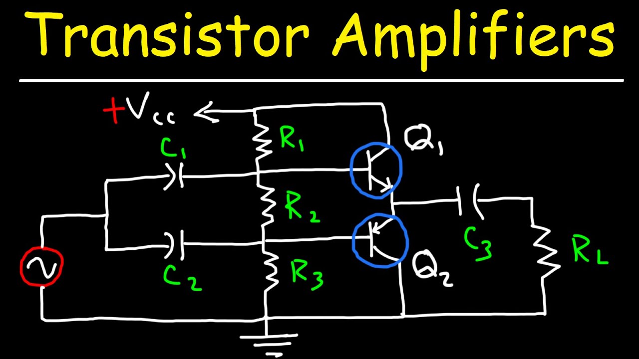
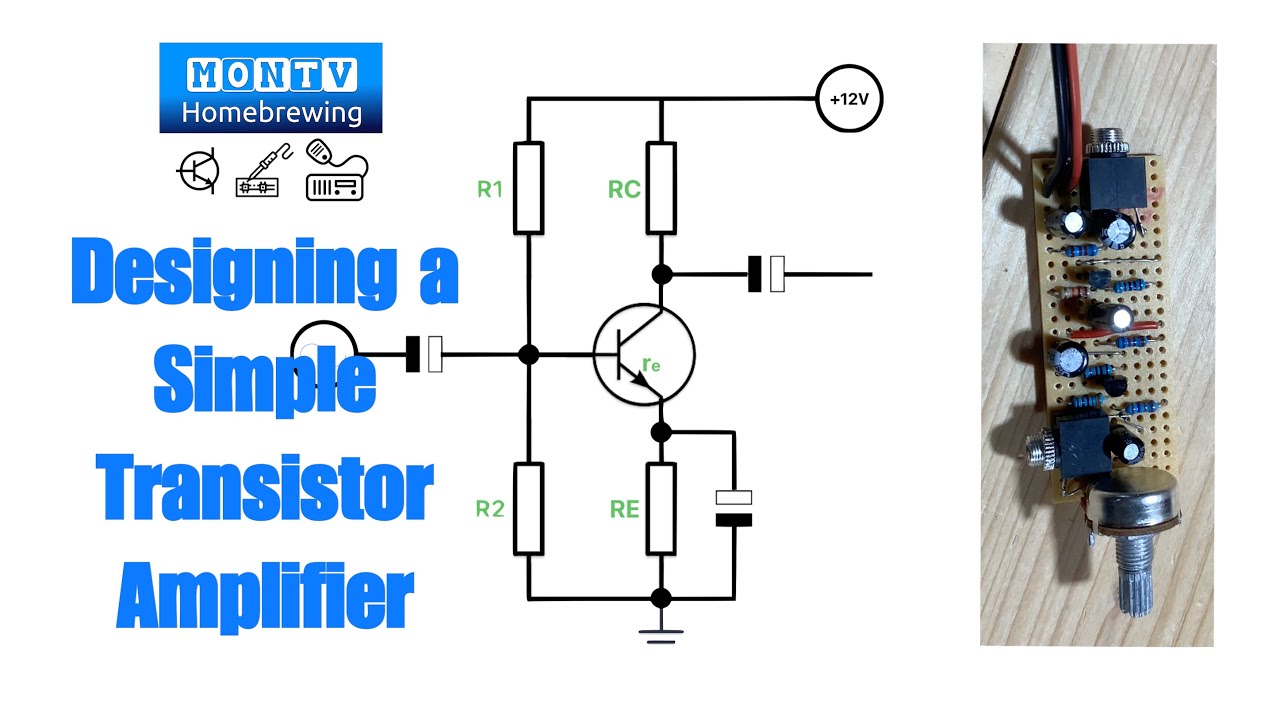
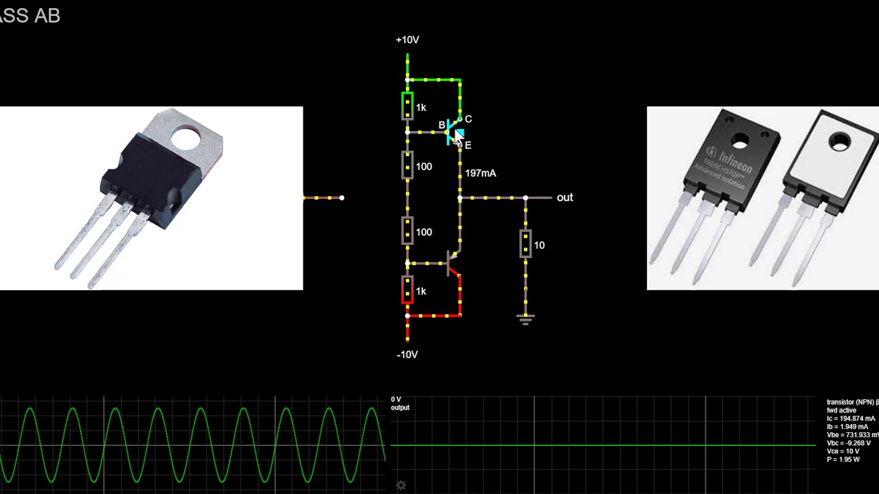
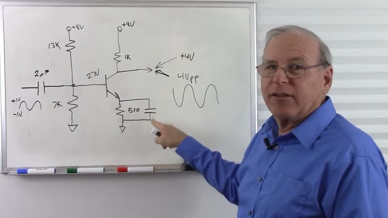
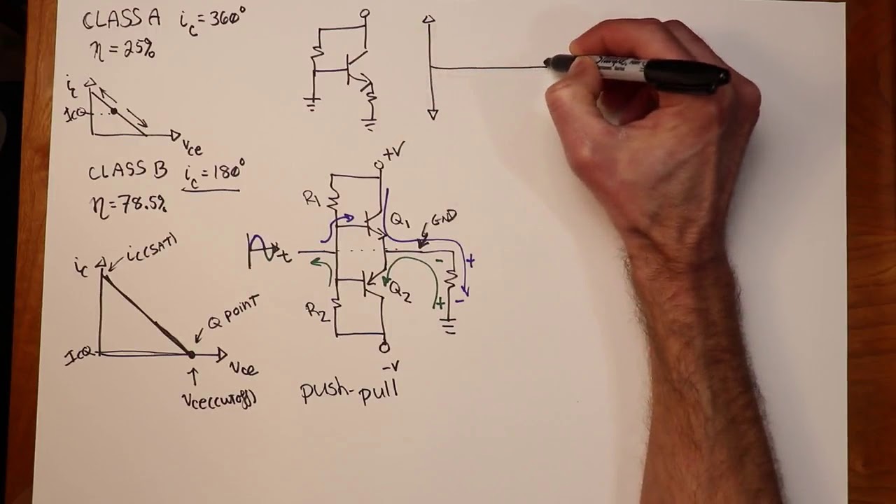
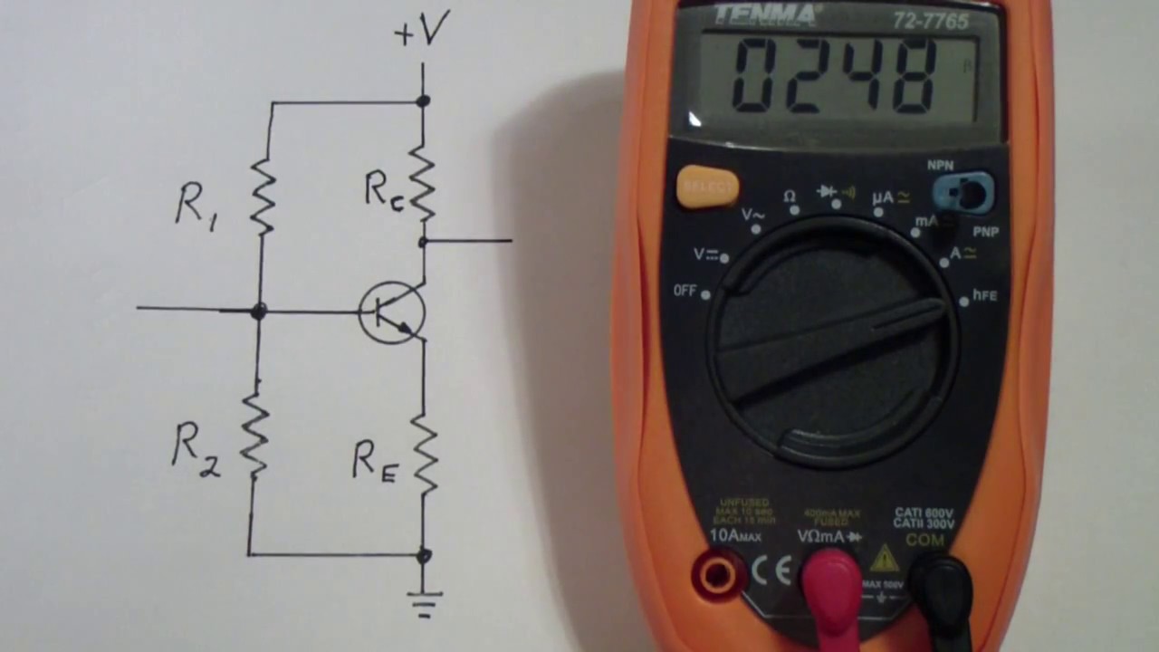
[Music] the classes that we are going to talk about in this course are not only used in power amplifiers but also used in audio amplifiers in quotes the first class that we are going to examine is Class A amplifier this amplifier circuit must look familiar to you because this configuration is nothing else but the common emitter circuit amplifier so we already talked about this circuit and we have also seen how to design one so let's just point out some facts about this configuration okay so Class A amplifier is a high gain amplifier with high linearity
in case of Class C amplifier the conduction angle is 360 degree as I explained in the previous course a 360 degree conduction angle means that the amplifier device remains active for the entire time and use complete input signal as we can see in this image there is only one active element which is nothing else but a transistor so the bias of the transistor remains on all the time right dooty is never turn off feature Class A amplifier provides better high frequency and feedback loop stability other than disadvantages Class A amplifier is easy to construct with
a single device component and minimum parts count despite the advantages and high linearity certainly it has some it has many limitations due to continuous conduction nature the Class C amplifier introduced high power loss also due to high linearity Class C amplifier provides distortion and noise ease the power supply and the BIOS construction need careful component selection to avoid unwanted noise and to minimize the distortion so we mentioned that Class C amplifier has high power loss right this means that it emits heat and requires heatsink space which sometimes is not available the efficiency is very poor
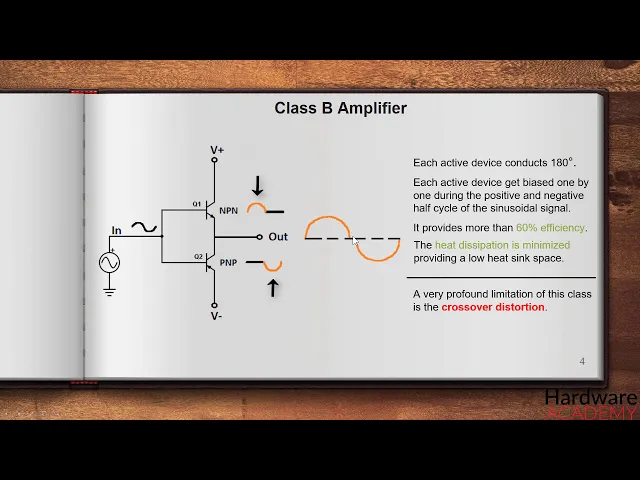
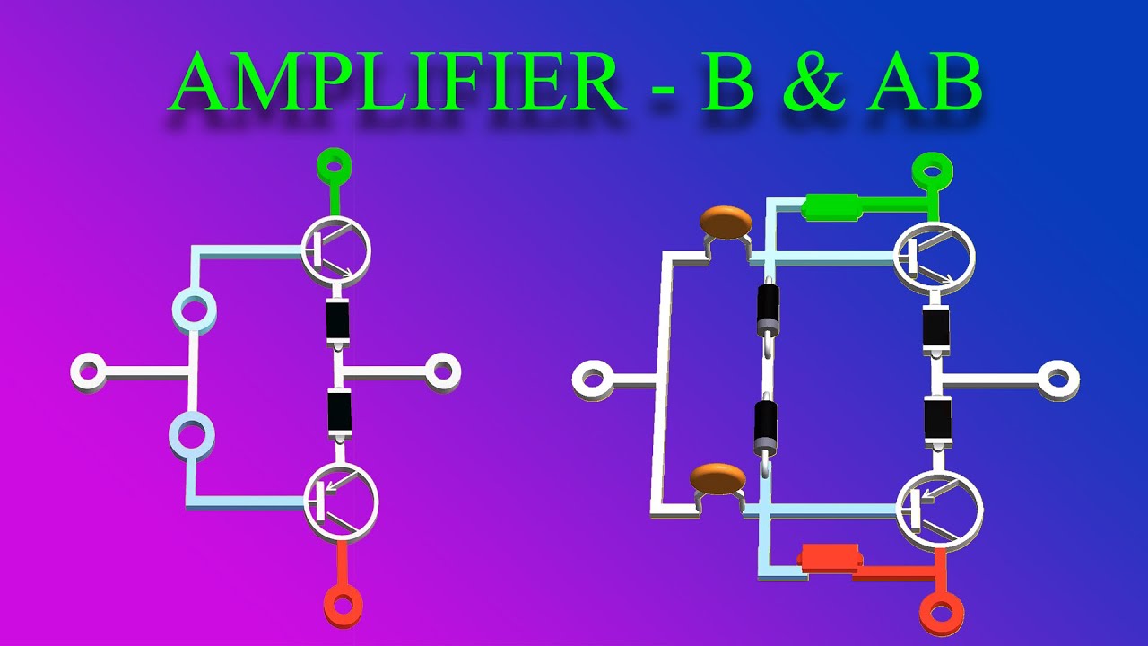
in Class C amplifiers theoretically the efficiency varies between 25 to 30 percent if used with the usual configuration the efficiency can be improved using inductively coupled configuration but the efficiency in such case is not more than forty or fifty eight percent use it is only suitable for low signal or low power level amplification purposes now that we highlighted some important facts about this class let's move to Class B the cleanse B amplifier is a bit different from the Class A as you can see here it is created using two active devices which conduct half of
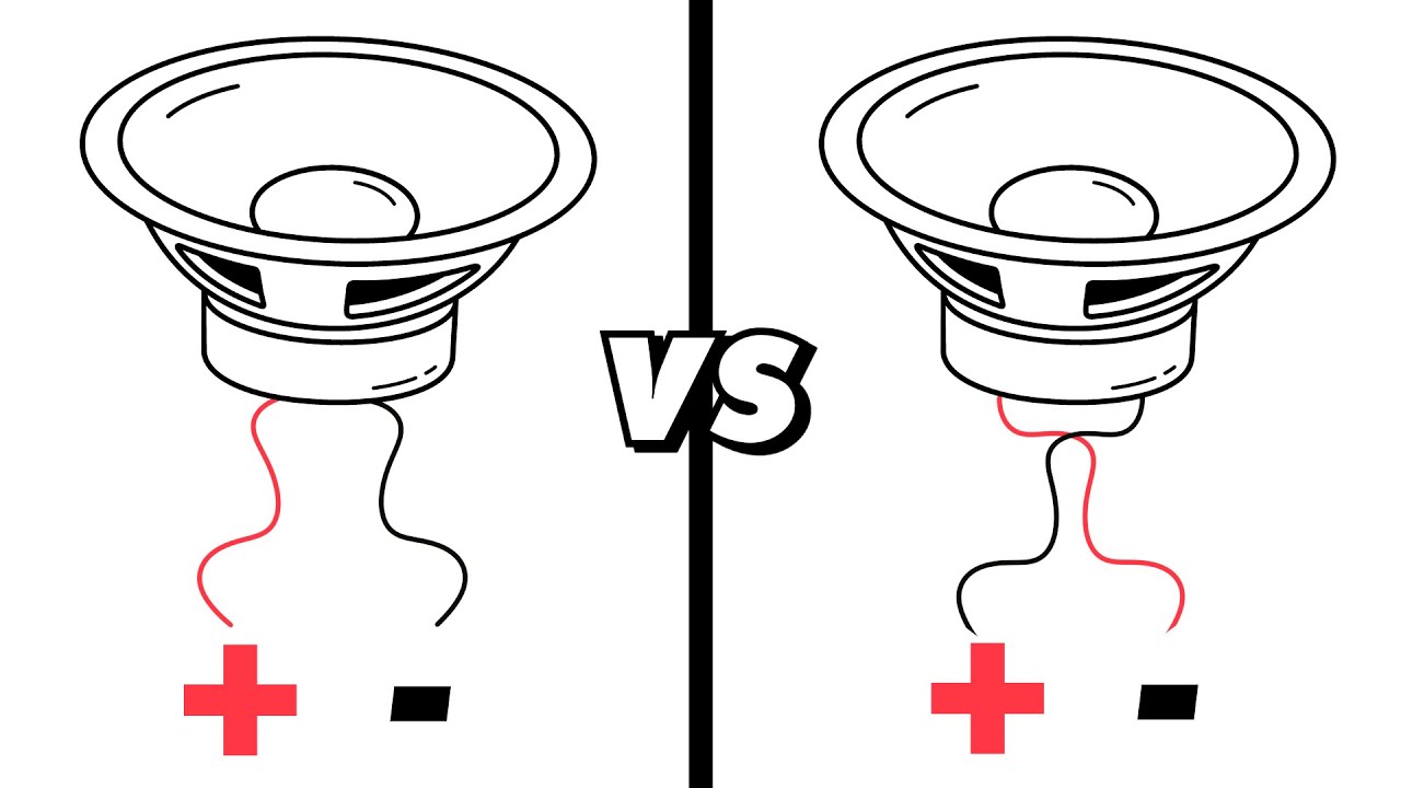
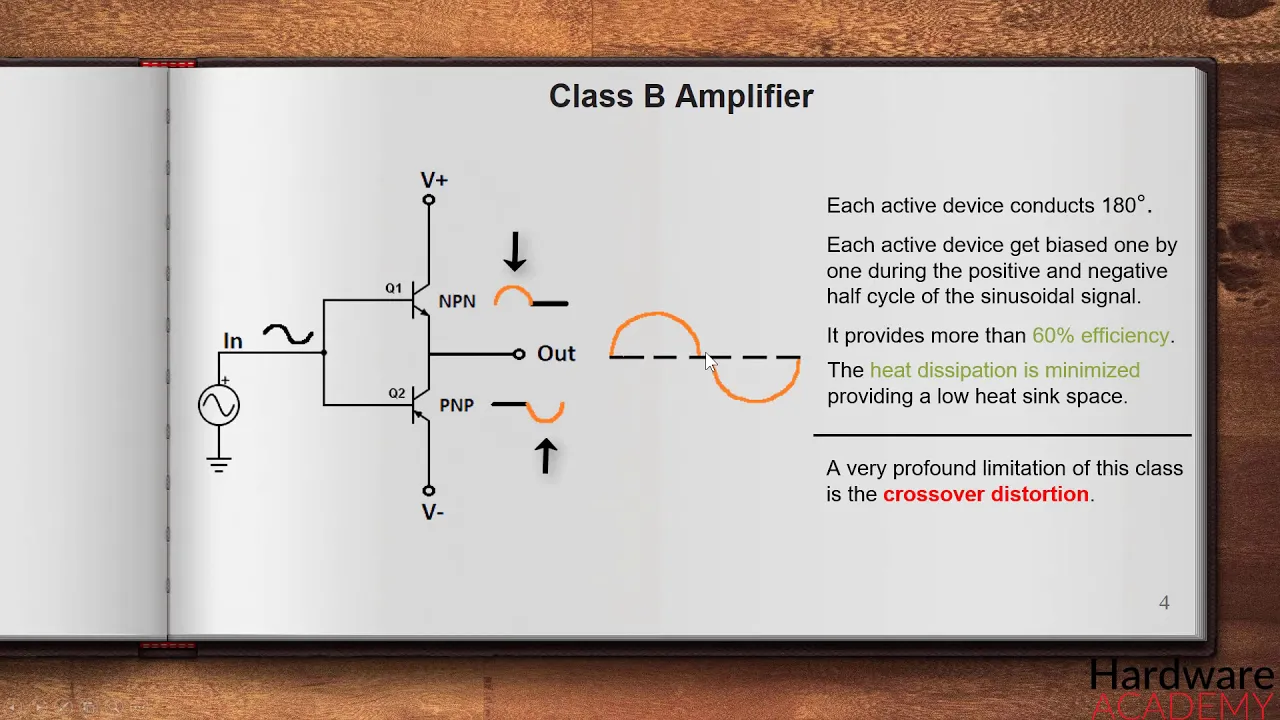
the actual cycle in other words they conduct 180 degree of the cycle so two devices provide combined current drive for the load if the circuit is used to provide audio signal amplification then the load is nothing else but a speaker right you might wonder how are these transistors biased well the bias is provided by the input signal which means that the input signal has to be higher than 0.6 volt and also the input signal has to go a negative in order to bias the PNP transistor don't worry if you don't understand how this circuit works
because in the next course we try we will try to simulate some of the classes so that you get a better understanding of how they work now let's just concentrate on theory a little bit and don't bother yourself if you don't understand exactly how the circuit works so this Class B amplifier consists of two active devices which get biased one by one during the positive and negative half cycle of the sinusoidal wave and use the signal gets pushed or pulled to the amplified level from both positive and negative side and by combining the result we
get complete cycle across the output because these two active devices are turned on one after another and because they conduct only half cycle the efficiency gets improved compared to the efficiency of a Class C amplifier which is twenty five to thirty percent the Class B amplifier can have an efficiency more than sixty percent also the heat dissipation is minimized in this class providing a low heatsink space but this class also have limitations a very profound limitation of this class is the crossover Distortion as two devices provides each half of the sinusoidal waves which are combined
and joined across the output there is a mismatch on in other words crossover in the region where two halves are combined this is because when one device complete the half cycle the other one needs to provide the same power almost at the same time when other one finished the job it is difficult to fix this error in Class B amplifier as during the active device the other device remains completely inactive the error provides a distortion in the output signal and due to this limitation it is a major fail for precision audio amplifier applications an alternate
approach to overcome the crossover distortion is to use the a B amplifier class a B amplifier uses intermediate conduction angle of both classes a and B use we can see the property of both Class A and Class B amplifier in this a B Class of amplifier topology same as Class B it has the same configuration with two active devices which conducts during half of the cycles individually but each device by us differently so they do not get completely off during the unusable moment or the crossover moment each device does not leave the conduction immediately after
completing the half of the sinusoidal waveform instead they conduct a small amount of input on another half cycle using this biasing technique the crossover mismatch during the dead zone is dramatically reduced but in this configuration efficiency is reduced as the linearity of the devices is compromised the efficiency remains more than the efficiency of typical Class A amplifier but it is less than the Class B amplifier system also the diodes need to be carefully chosen with the exact same rating and need to be placed as close as possible to the output device in some sync reconstruction
designers tend to add small value resistors to provide stable quiescent current across the device to minimize the distortion across the output apart from the Class A B and a B amplifier there is another amplifier called as Class C it's a traditional amplifier which works differently than the other amplifiers classes Class C amplifier is tuned amplifier which works in two different operation modes tuned or untuned the efficiency of Class C amplifier is much more than the a B and a B so a maximum 80% efficiency can be achieved in radio frequency related operations the interesting thing
here is that Class C amplifier uses less than 180 degree conduction angle and during the engine mode the class II amplifier unfortunately gives huge distortion across the output but in typical uses Class C amplifier gives 60 to 70 percent efficiency the output amplitude is a nonlinear function of the input so Class C amplifiers are not used for linear amplification they are generally used in radio frequency applications including circuits such as oscillators that have a constant output amplitude and modulators where a high-frequency signal is controlled by a low frequency signal so it works fine with simple
sinusoidal waveform but may have unacceptable distortion with complex waveform as the Class C amplifier the transistor conducts for less than 180 degree of the input signal on the other hand Class D amplifiers are way more popular and wider spread as Class C amplifiers it's one of my favorite in terms of functionality and we will also try to simulate the circuit in our simulator in the next course while Class A B and a B are classified as analog designs Class D amplifiers are classified as switching designs as you can see the circuit is very different from
the others this is just a semi block diagram of Class D amplifier but in the last course we will see a full functional circuit so Class D amplifier is a switching amplifier which uses pulse width modulation if you are wondering what post width modulation is I advise you to look that up on the internet because it's very important technique used in F Ronix basically positive modulation or PVM is a technique for getting analog results with digital means so digital control is used to create a square wave which is a signal switched between on and off
right as the name implies the width of the square waves are modified in order to vary the amount of current that flows to a device all right so the conduction angle is not a factor in such case as the direct input signal is changed with a variable pulse width in this class the amplifier system the linear gain is not accepted as they work just like a typical switch which have only two operations on or off before processing the input signal the analog signal is converted into a poor stream by various modulation techniques and then it
is applied to the amplifier system as the pulses duration is related with the analog signal it is again reconstructed using low-pass filter across the output remember that Class D amplifier is the highest power efficient amplifier class so it has smaller heat dissipation so small heatsink is needed the silk which requires whereas switching components like MOSFETs which has low on resistance it is widely used apology in digital audio players or controlling the motors as well but we should keep in mind that it is not a digital converter