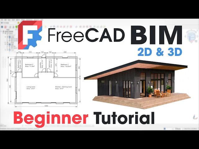
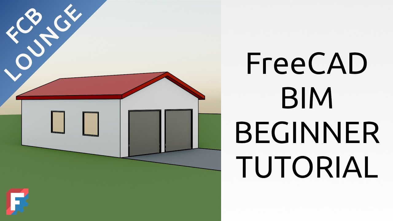
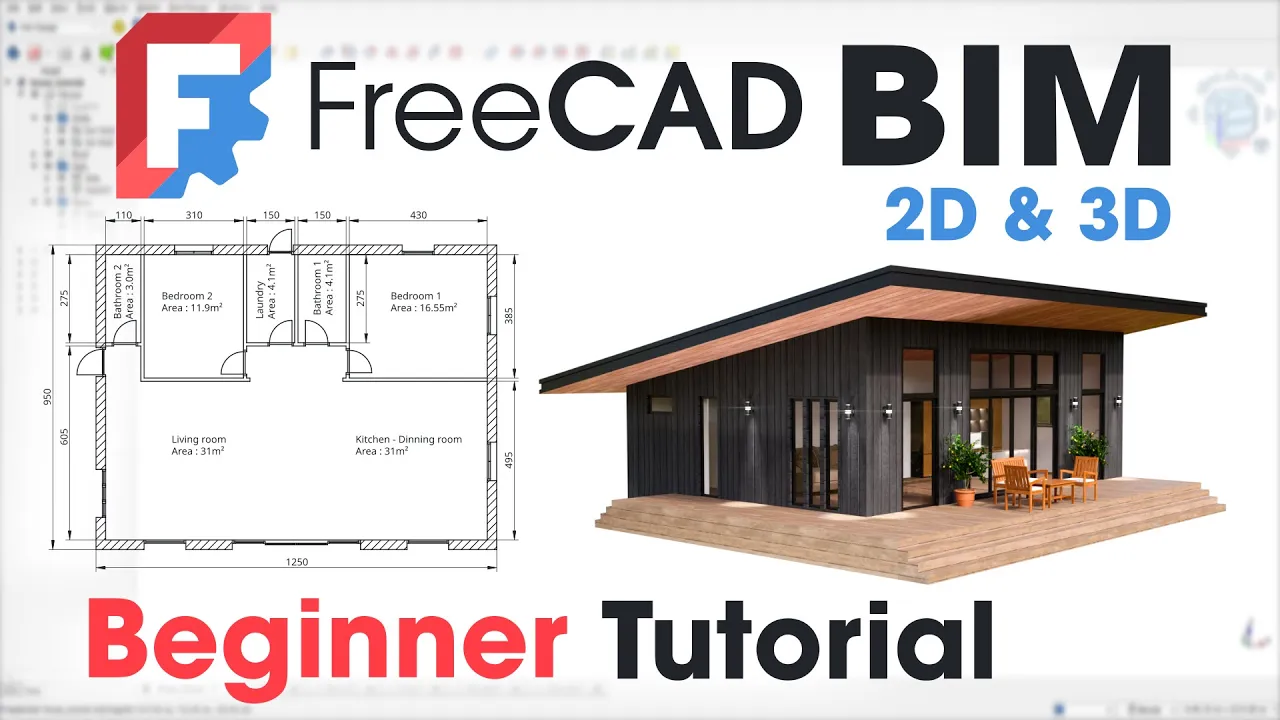
freead with its BM workbench offers a free and versatile solution for designing homes and building you'll be surprised at how quickly you can produce highquality professionall looking files even if you're new to this software this video is a tutorial specifically designed for beginners who are new to freead and want to learn how to use it for building information modeling and architecture projects we will cover the essential tools and techniques that are commonly used in Bim workflows the video is divided into chapter allowing you to easily jump to the specific topic that interests you by the
end of this video you will have acquired the necessary skills to create a detailed 3D model of this house using freecad you will also learn how to generate various 2D drawings including floor plans sections and elevations which are essential for construction documentation and the best part of all of this it's completely free so let's give this poor caveman a roof over his head when you first open freead a dialogue box appears asking you to choose a language working units and navigation system I usually stick with the default options and select blender as the navigation system
but since we're working on architecture the standard is to use centimeters so we need to change the units and set them to building Euro I'm also changing the navigation style for the blender one I'm selecting the light theme to make the icons easier to see for you since we're working on an architectural project we'll spend most of our time in the BM workbench so let's start by clicking on the create an architectural project icon it might take a few seconds for the workbench to open the first time as it's loading all the tools a window
will pop up introducing you to the workbench's features and providing links to the documentation you can click okay to proceed in the following window you'll find various display settings just change the first drop- down menu u 2 cm these settings aren't critical and can be modified at any time freead jumps straight into the action so zoom out a bit with your mouse wheel before we start let's adjust the interface close the report view to maximize workspace and drag the taskbar to the right side of the screen to improve accessibility of the tools dock the sky
blue snapping tools to the right hand side of the interface drag the general modification tools to the left side of the second line and finally Drag The annotation tools represented by a yellow letter A to the right of the second line you should now have a better overview of all the tools now let's move on to the fun part to start a BM project we have several options personally I like to begin by creating a building a building is a container for all the 3D objects related to our construction to create a building simply click
on the building icon you'll see a new item called building in the tree view to keep our project organized let's rename the building to something original and not common at all like house you can rename the building with the F2 key while our project only requires a single level it's good practice to structure our project using levels similar to how multi-story buildings are organized we'll store all level specific elements like walls and slabs within the level it's a subc container of the building with the F2 key you can rename it level zero drag and drop
it into the house container the most challenging aspect of this workbench is understanding how the tools work some tools require sketches others need to be attached to existing objects While others are Standalone before we start let's go over the different tools the tools with yellow dots are for creating draft note that these draft geometry can't be constrained to each other and are harder to modify once created I prefer using the Sketcher tool with red dots especially if you're coming from the part design workbench you can constrain and give Dimensions with this tool next on our
lease the 3dbm tools these tools are specifically designed for architectural elements allowing you to create a wide range of building components such as walls slabs stairs roofs and doors they also enable you to convert objects created in other workbenches by assigning the appropriate IFC class some tools require preliminary Ary sketches the blue tools allow you to perform various operations on both sketches and 3D elements these operations include moving copying resizing mirroring and arraying the manage tools allow you to modify and add IFC properties to your objects while it's important to structure your files correctly and
assign the appropriate IFC classes to all your models for interoperability we won't be focusing on that in this tutorial the last tools are the annotation tools these tools allow you to create Dimensions annotations and section view directly into the workbench without using the tech draw workbench let's start building our house by creating the main slab just like in real life we need to Define its Dimensions first there are two ways to create our slab the first is by using the yellow dot tools to draw a rectangle if you're familiar with AutoCAD this is a similar
drawing process personally coming from software like Fusion 3 60 or solid works I prefer using the Sketcher as I find it more intuitive so you'll click on the icon with the white line and red dots notice that the view automatically orients itself perpendicular to the top view making it easy to draw your slab as if on a piece of paper our goal is to recreate this sketch which includes the house front deck and side deck you can find the sketch image in the description for reference to begin outlining our house we'll utilize the rectangle tool
Click On the Origin to establish and snap the first corner of the rectangle subsequently input the dimensions 1250 for the width and 950 for the height of the rectangle these Dimensions will determine the overall size of our house footprint to improve readability you can move the dimensions to a more convenient location we will proceed to define the deck's perimeter using the polyline tool start drawing a vertical line from the origin if the line is perfectly vertical you'll see a red vertical constraint appear along the line continue the line horizontally extending past the end of the
rectangle next draw a vertical line upwards ensuring it ends within the rectangle finally draw a horizontal line from the end of the vertical line connecting back to the rectangle you can end the tool by right clicking or pressing escape using the dimension tool we'll input the deck dimensions 300 CM for the width of the front deck 200 CM for the width of the side deck and 750 CM for the length of the side from the red axis the sketch contains multiple closed Loops which is not ideal we'll convert the internal lines to construction lines however
there's an issue with the left line as it doesn't intersect with the deck line to resolve this we'll employ the split tool to introduce a new vertex at the intersection Point select both the newly created point and the intersection point then click on the constrained coincident icon to merge them to prevent the two Central lines from affecting subsequent operations we will convert them into construction lines select them and activate the construction line tool the sketch is finished and all constraints are applied click close to exit if you struggle to see the created sketch you can
hide the grid by clicking on the grid icon in the right side menu to create the slab from this sketch you need to click on the slab icon which is represented by a Yellow Block in the top bar tools menu this action fills the sketch and extrude it downward with a flat value of 20 cm we can modify this value by selecting the slab in the tree View and going in the left side data properties panel and under height adjust the value to 60 cm to obtain a thicker slab to keep the file organized in
the tree view you can drag and drop the slab into the level zero container by selecting the slab and pressing F2 you can rename the slab by main slab we'll now draw the exterior walls using the red sketch tool we can hide the slab by clicking on the icon next to it as it would be easier to sketch the wall without it next click on the Sketcher icon to start drawing our goal is to replicate this sketch which depicts a rectangle with an interior offset the dash line represents the exterior wall boundaries while the green
line indicates the interior wall boundaries although the walls tool automatically creates wall thickness we will draw these boundaries explicitly this will serve as a foundation for creating interior walls which will originate from these interior boundaries you will see in a minute let's use the rectangle tool to draw the exterior walls starting from the origin and input a dimension of 1,250 CM for the width and a dimension of 950 CM for the height we can adjust the dimensions for a more aesthetically pleasing result to create the wall thickness let's select all the edges and use the
offset tool in the left hand menu check the add offset constraint box and enter a value of minus 30 cm for the offset the offset operation has created Four Construction lines which are not constrained we will place them at the center of each respected edges to do this select the edge next select one point of the construction line and apply a symmetrical constraint by clicking on the corresponding icon the construction line will move to the center of the edge you need to repeat this step for the four edges we will use these construction lines to
draw and constrain the sketch of the interior walls after that before closing the sketch select the outer edges and convert them to construction lines using the appropriate tool the sketch is fully green indicating it's fully constrained we can exit it by clicking on the close icon to keep the file organized we can rename the new sketch BYT wall using the F2 key in order to create the exterior wall we will use the wall tool to use it first select the created sketch and click on the yellow icon with a brick wall this tool will automatically
created closed walls with a height of 300 cm and a thickness of 20 cm to adjust these values you need to select first the wall object in the tree View and go under the data properties in the left panel change the height for 350 cm and the width for 30 cm when you make the main slab visible again you can see that the exterior wall isn't perfectly align with the edge of the slab when the wall is created as default it uses the sketch at the center of the wall in our case we have drawn
the inside line of the wall so the alignment should be set to left instead of Center we can see now the wall is perfectly aligned with the slab with the F2 key we can rename the new wall by EXT wall and drag and drop it into the level container we'll hide the exterior wall and the slab and expand the exterior wall to see its sketch before creating the interior walls click on the Sketcher icon to create the sketch for the interior walls our objective is to recreate this sketch which is an open Contour the wall
tool accommodates this type of sketch note that the different Lines within the sketch will represent the center lines of the respective walls to start we will create a carbon copy of the exterior wall sketch within this sketch click on the carbon copy icon and then select the S EX wall sketch in the tree view this tool will import the sketch while preserving its constraints which we will then use as a basis for constructing the interior walls we convert the green lines into construction Lines by selecting them and clicking on the construction line tool let's use
the line tool to create a horizontal line separating the living area from the bedrooms start and end your line on the inside construction lines of the previous wall with the dimension tool give a height of 500 from the inside right corner of the dotted rectangle employ the line tool to create the separation between the bedroom and the bathroom start your line on the top dotted Edge and end it on the last created line repeat the same process for the line separating the second bedroom and the laundry draw a horizontal line between the two most recently
created lines to represent the corridor between the two bedrooms draw a vertical line starting at the midpoint of the top dotted Edge and extending downwards until it intersects the most recently created horizontal line this line will represent the separation between the bathroom and the laundry room to stop using the line tool press Escape or right click on your mouse to ensure both Central rooms are the same size we need to make the two vertical lines symmetrical about the center line select the top point of the right line then the center line followed by the top
point of the left line and click on the symmetrical constraint tool with the dimension tool we give a width of 110 CM for the corridor and a width of 160 cm for the bathroom as the bathroom and the laundry are symmetrical it would give a width of 160 cm to laundry 2 using the line tool we create the separation between the second bedroom and the second bathroom by creating a vertical and a horizontal line the newly created horizontal line should be aligned at the same height as the existing horizontal line to achieve this select the
end points of both horizontal l lines and apply a horizontal constraint finally with the dimension tool give a width for the second bathroom of 115 CM while the sketch is fully constrained we might not know the exact dimensions of certain elements to determine the size select the points and check the reference box in the dimension tool this creates a driven Dimension that won't strain the sketch we can repeat this process to know the width of other rooms we can now exit the sketch by clicking on the close button with the F2 key we rename the
new sketch by S wall to create the interior wall with a newly created sketch selected click on the yellow brick wall icon similar to the exterior wall this tool creates walls with a default height of 300 cm and a thickness of 20 cm to adjust this select the wall object in the tree View and go in the data properties tab in the left scroll to find width and change it to 10 cm also change the height of the walls for 350 CM once again use the f to key to rename the wall for INT wall
and drag and drop it into the level zero container you can create a folder to store all the walls in the same place to create a folder click on the icon folder in the top bar with the F2 key you can rename it to walls next drag and drop the folder into the house building container drag and drop the two walls objects and finally drag the walls folder into the level zero container you can make the main slab visible again and appreciate the work you did until now to begin the process of adding windows and
doors to our model we will first need to select the specific wall element where we want to create these openings in the project tree locate and select the element labeled EXT wall once selected click on the icon that represents the door creation tool the menu below provides various parameters for creating different types of doors and allows you to modify General door properties like height and width as well as more specific settings such as frame position and dimensions if you try to place the door on the wall you'll notice that it's difficult to snap to make
it easier activate the snap endpoint option in the snap menu on the right sometimes the door can snap to another object to prevent this snapping you can hide the main slab in the tree view right now the door can only snap to end points for more flexibility in door placement enable the snap near option in the snap tool menu this allows you to place the door more freely to place the door precisely you can enter a value in the local X field however I found that this method doesn't always result in the desired door placement
in my experience experience this placement method isn't very intuitive to use my Approach is to add reference points directly to the wall sketches this allows me to precisely snap doors and windows to these points without worrying about their exact placement so we will delete the door we just create the door object is stored into the EXT wall object so select it and delete it by pressing the delete key to create reference points we'll need to go back into the sext wall sketch right click it and choose edit sketch our objective is to add a series
of points to the sketch we will then add Dimensions between these points defining the sizes of the doors and windows as well as the spacing between them for reference the image of the sketch is provided in the description we will Begin by focusing on the front face of the wall as observed in this front view there are three distinct Windows therefore we need to add six points along the edges so select the point tool and add six points on the bottom Edge once the points are placed utilize the dimensioning tools to establish Dimensions as shown
in the drawing remember that the wall thickness is 30 cm so you'll need to subtract 30 cm from the overall dimensions at the beginning and end of each wall Edge to Center the large window select one endpoint then the blue axis followed by the other endpoint apply a symmetrical constraint using the corresponding icon using the dimensioning tools determine the remaining missing Dimensions we'll repeat this process for the remaining four sides the plans for each side will be provided as a reference to speed things up the video will be played at 3x speed feel free to
adjust the playback speed at 0.35 if you want the video at the real speed all these repetitive actions remind me of my terrible biology teacher in high school who used to say that to remember something you had to learn it and forget it three times here with all these Dimensions we're adding I really think you will not have to repeat this three three times to know how to do it there's a French expression for that which could be literally translated as it's by forging that one becomes a blacksmith that's the English equivalent of practice makes
perfect I'm curious to know if there are equivalence to this expression in other languages please let me know in the comments how you would say this in your language or if there is another expression in English I apologize for the interruption please continue with your Hardwick congratulations you finished adding all the reference points you can now exit the sketch by clicking on the close icon now we'll place the doors and windows using the reference points we just created to begin we will make the sext wall sketch visible so as to get a clearer view of
the sketch let's hide the slab you'll notice that the sketch points are small to make them more visible select the sketch and go in the properties view panel scroll down to find the point size and change the value to eight in the 3D viewport you should now see that the sketch points are much larger I usually position windows and doors from the interior to create a recessed effect on the exterior wall to add the first window click on the yellow window icon as you can see you can directly snap the window to the points we
created earlier in the right side menu give the window a width of 130 cm and a height of 210 CM be sure to input CM at the end of the value otherwise it wouldn't work next snap the window on the second point of the sketch and click to confirm you can notice that the window didn't cut through the wall I don't know if it's a bug or not I noticed that I first select the wall before creating the window I don't have this issue at all I'm not sure if it's related or not in the
tree view delete the sketch 003 and the window which was affected to the int wall delete the sketch 042 let's do things in the right order first select the EXT wall in the tree view then click on the window icon freead remembers the last values you entered so you can directly place the window in its desired location you can see that everything goes as planned and the EXT wall has been successfully cut too repeat the same process for next window in the right panel adjust the preset to Sliding for Pane and change the width to
400 cm next snap the windows on the fourth point of the sketch the third window will be identical to the first so instead of recreating it like a caveman we'll use the copy tool this will allow us to duplicate and move the window simultaneously to do this select the window object in the tree View and click on the copy icon in the toolbar click on the bottom left point of the window and snap the window on the sixth point of the sketch you can zoom if you struggle like me now let's add the upper Windows
select the window tool from the toolbar in the right hand menu set the height to 100 cm and snap the new window on the left top corner of the first window for the windows above the large one we'll place four identical 100 cm x 100 cm windows so click on the window icon to create one in the right menu adjust the width to 100 cm snap the window into the left top corner of the big window and left click to place it we will copy and move this window three times so as to obtain the
same length as the big window so select the window 004 and click on the copy icon next select the bottom left corner of the windows and move the windows to the bottom row corner you need to repeat this process two more times freead offers an array features which could be more efficient to to create for exactly Windows however if you use it you will not be able to cut through the wall so it seems you were stuck to repeat this process three times for The Last Window of this facade it's the same as the first
one so select the window 003 in the tree View and use the copy tool select the left bottom corner of the window and move it to the left top of the left window congratulations you finished to place all the windows on the first facade take a time to admir your work and check if everything is okay before I let you fly the coupe let me show you how to place a window at a specific height from the ground to place the window at the correct location Begin by snapping it to the reference point that you
previously created within the sketch once the window is aligned with the reference point you can then adjust its vertical position by modifying the z-axis value you can adjust this value with a move tool or directly in the properties data panel on the left let me show you click on the window icon to create one change the preset of the window to open two pane give a value of 120 CM for the width and 110 CM for the height next snap the window into the second point of the sketch left click to confirm the position in
the tree view select the window 009 and click on the Move tool in the top toolbar menu left click on the top corner of the window and press Z to constrain the move on the z-axis we want to align the height of the window with the height of the big right window so click on the right corner of the big window it will place the small window exactly to the same height as the big window if you want to place the window to a specific place from the ground you need to First select a bottom
corner of the window next press Z to constrain the move on the z-axis and then enter a value for the height or you can directly adjust the position in the properties data panel in the placement setting you should now have everything to place the remaining doors and windows if you're unsure about a Windows size or placement refer to the drawings in the description I've sped up the video 3x but you can slow it down to 0.35x if needed and if you want to catch everything if you you find yourself getting weary of placing all these
doors and windows recall this proverb perseverance is key e congratulations you have now finished placing all the windows and doors on the exterior walls it was a lengthy process but you completed it successfully we will now move on to placing the doors and openings on the interior walls this should be a bit easier as we'll be working in a more free form manner we'll follow the same process for the interior wall as we did for the exterior in the tree view select the int wall and then click the door icon in the right panel choose
simple door as the preset and set the width to 80 cm we'll place this door which will be for the first bedroom approximately in the middle of the corridor keep in mind it might be a bit tricky to find the perfect angle to place the door in this spot but with a little patience you'll get it left click to confirm the position of the door we will repeat the same process for the four remaining doors e as you can see the laundry room door has also cut into the living room wall to adjust the cut
depth select the door in the tree view go to the properties Tab and in the data panel set the whole depth to 10 cm after adjusting this setting the opening into the living room should be closed you'll likely encounter the same issue with the two bathroom doors you'll need to adjust the settings for that door as well or you can use the copy tool to avoid this issue we could create each wall independently when performing Boolean operations we would only affect the target wall not all walls at once alternatively we could set a default hold
depth for all doors for me the most efficient way would be to adjust the settings for one door and then copy it to the other locations this avoids recreating the door and modify the parameters each time we're going to start creating openings in the wall to do this we'll use the same door creation tool as before change the preset to opening only and give a width of 115 CM place the opening at the bottom corner of the wall it could be easier to hide the EXT wall to achieve this the great thing about freecad is
that everything we've done so far is parametric so if we make a mistake we can easily fix it you'll see why later we're going to place the second opening for the Cor click the door icon and change the width for 320 CM next place the opening between the two wall of the corridor left click to accept the position as you can see the same issue has occurred with the bathroom wall the Boolean cut has affected it as well so go in the data panel and change the value of the whole depth to 10 cm as
you can see the opening is too large and it extends beyond the door frame to fix this select opening 001 in the tree View and go in the data panel scroll down to find width and change the value for 310 cm I don't think this is the best spot for the opening luckily with freead we can easily modify our design before making these changes I'm going to show the slab and hide the S EXT wall sketch as we don't need anymore to adjust the big opening select the opening 001 in the treeview then go in
the data properties panel scroll down to find the width value and adjust it to 290 CM after that scroll up to find a position setting and change the x value for 10 cm I'm much happier with this size and placement now we're going to model the roof of our house depending on the roof's complexity we can either use the dedicated tool in the BM workbench or model it in the part workbench and then classify it using IFC in our case we need a simple single slope roof so the dedicated tool in the BM workbench should
be sufficient first we will hide the interior wall and keep the slab and the exterior walls visible we're now going to sketch the roof footprint let's start by clicking the Sketcher icon the objective will be to recreate this sketch which is basically a rectangle the roof will have an overhang of 150 CM above the deck and 100 cm for the two remaining sides select the rectangle tool and draw a rectangle that covers the entire exterior wall and extends over the decks with the dimension tool give a dimension of 1,500 CM for the top Edge next
from the red axis to the top right corner give a horizontal dimension of 150 CM from the bottom right to the red axis give a vertical dimension of 150 cm and finally from the origin to the right Edge give a horizontal dimension of 100 cm the sketch is finished in fully green you can exit it by clicking the close icon as usual let's rename the sketch using F2 we'll call it s roof now we'll move the sketch to the desired height for the bottom of the roof with the sketch selected go in the data properties
panel and change the zv value for 230 CM you will see the sketch goes higher in the viewport you can check your model in the left view to see if the sketch is at a good height it looks okay for me to create the roof you need to First select the sketch and then click the roof yellow icon as you can see multiple slopes have been created following the outline of the sketch to edit them double click the roof object in the tree view a window will pop up on the right allowing you to adjust
various parameters such as roof shape slope and overhang a description of all the parameters and their functions is also available feel free to experiment with the settings to see how they affect the result in this case we want a single slope roof so we need to find the Cor cor ID for our slope and set the run of the others to zero the ID for our slope is the number one for the Run value we need to give a value of 12,000 mm and give zero for the other ID you can switch to a left
side view for a better perspective we need to set the overhang to zero because we have already Define them in the sketch we can also give a thickness of 300 mm the angle of the slope is too steep we can adjust it to 6.5 de to obtain a good result that's look good to me we can close the tool now we'll cut the walls to match the roof slope but before that we drag and drop drop the roof into the house building container to keep the file organized next select the roof and the EXT wall
while maintaining control and click the less blue icon as if by Magic the exterior walls are cut following the slope of the roof repeat the same operation for the interior walls we're almost done modeling the house we just need to add a slab for the back door and three sets of stairs to create the back slab we need to hide the roof by clicking on the eye icon in the tree view next click the Sketcher icon to start drawing the footprint of the slab use the rectangle tool to draw a rectangle above the top edge
of the exterior wall use the dimension tool to set a horizontal Dimension between the top right corner of the rectangle and the green axis give a value of 625 CM set a value of 100 cm for the right Edge for the top Edge set a value of 160 cm and finally give a dimension of 950 CM between the bottom right corner of the rectangle and the red axis the sketch is fully constrained you can close it with the sketch selected click on the slab icon with the F2 key rename the slab to backs slab then
drag and drop the back slab into the level zero container change the value of the height of the slab into the data properties panel set the value to to 60 cm then to keep the file organized create a slab folder move the folder into the level zero container and finally drag and drop the two slab objects into the folder we will now proceed with the modeling of the stairs in the BM workbench you can create stairs with just one click locate the yellow stair icon in the toolbar menu and click it to generate stairs by
default freead creates stairs with railings in the tree view you can expand the stairs object and delete the two railing and the associated wire as we don't need in our project to modify the stair parameters go to the data properties on the bottom left we'll adjust the number of steps to four and change the height to 60 cm and the length to 60 cm we want a solid staircase without any space underneath so we need to adjust the structure thickness to 36 CM there are countless parameters you can adjust to customize your stairs for our
project the one we created is perfect now we're going to move the stairs to the back slab to do this we will use the move tool select the stairs in the tree View and then click the move tool select the bottom right point of the stairs and click to accept then move the camera to snap the point of the stairs stare on the bottom left corner of the back slab we're going to add another staircase to the side deck before creating it let's measure the length of the Edge by selecting it and going to the
tools menu then measure we know now that we need to create a 200 CM wide stair case you can exit the tool by clicking on close we're going to duplicate the object using the good old classic trusty control+ C contrl plus v shortcut this allows us to create an independent copy which is is essential since we'll be changing its width in the data properties panel find the width of the new stairs and change the value to 200 CM next select the stair 001 and use the rotate tool select two point of the edge and apply
a rotation of 270° press enter to accept the rotation next select the stair 001 and click the move tool select the bottom right corner of the stair and snap it to the bottom right of the deck we will repeat the same process for the big stairs in the front select the long Edge next go click the tool menu and choose measure the measure is 1,450 CM so we need to create a stairs with this value for the width select the stair 001 and contrl C plus contrl v to create a duplicate in the data properties
adjust the value of the width to 1,450 CM next use the rotate tool to apply a 180° rotation and finally use the move tool by selecting the left bottom corner of the stair and snap it to the bottom point of the Big Slab as usual create a stairs folder to store the three stairs we just created with the F2 key rename its stairs then drag and drop the three stairs in the folder and move the folder in the house building container we finished modeling the entire house the great thing about freead is that we can
automatically generate various plans such as elevations floor plans and side views let's make the roof visible to see the entire 3D model to make maintain organization and facilitate future modifications we will create a dedicated folder to store all of the 3D elements that comprise our house model this folder will be named 3D model drag and drop the house building in the 3D model folder next create a new folder and rename it 2D drawings we'll Begin by creating a section plane to cut through the house and produces section drawing so click the icon of the section
plane in the top toolbar this will create a section plane at the origin for our section view we want to see the windows that are 100 cm above the ground so we need to adjust the section plane height to 110 CM next we need to specify which objects we want to see in the section view double click the section object in the tree view to open its properties next go to the tree View and select all the objects you want to see in the section view in our case select all walls windows and doors once
you've selected the objects click on the add selected button if you've accidentally selected any sketches remove them as they will create unnecessary lines in the section view you can click okay to close the panel to generate the plan directly in the BM workbench select the section object and then click on the shape base view icon a new object representing the section view drawing appears in the tree view you can move it by right clicking and translate move it to the left of the scene we've successfully generated a section view of the house using this tool
as you can see there's an error in our plan especially the walls of the second bathroom let's investigate it I think the issue is caused by the opening it's too deep and not centered correctly in the tree view search the opening object and select it to access his data properties scroll down to adjust the value of the depth hole to 10 cm it's better but we can see the opening isn't not properly line with the wall to correct this scroll down in the data properties and change the value of the width from 115 cm to
110 CM there's still a line showing in the plan which means the hole isn't deep enough so the opening isn't cutting the wall completely let's see the 3D model the whole depth of 10 cm creates a zero thickness surface to correct this we need to change the value of the whole depth to a bigger one like 15 cm it should resolve the issue let's see on the drawing this looks perfect to me now we can also display door opening lines directly in both the drawing and the 3D model to do this select all the doors
you want to show the swing path for then scroll down in the data properties and set the value for symbol plan to true this will automatically draw the opening lines for All Doors both in the 2D plan and the 3D view to change the do's opening Direction simply right click on it and select either invert opening direction or invert hinge position depending on what you want to do I'm going to adjust this setting so that all doors open the way I want them to as you can see in the section view the doors have been
updated correctly once you've adjusted the door swing directions move the section object and shape view to the 2D drawing folder now we're going to create a layout of this section view to do this you have two options create the layout directly in the BM workbench using The annotation tools or use the tech draw workbench which is specifically designed for creating drawings we will do the option so go to the workbenches menu and select the tech draw workbench the first step is to create a new drawing sheet so click the icon inserted default page using the
F2 key rename the sheet floor plan and move it in the 2D drawing folder next go to the template properties and change the template to a blank A3 landscape sheet as you can see freecad offers multiple Style of templates you can also use one of your creation your file should be in SVG to be open to bring the section view into the layout select the shape 2D view object and click the insert view icon freecad initially displays a front view of the object to see the lines we'll switch to a top view by clicking the
downward blue arrow since the lines are at a one to one scale we need to change the view scale to one on 45 go to the properties and set the scale to custom and then input 145 now the section view should be displayed correctly on the sheet click okay to confirm let's create a simple layout by adding some Dimensions to get the sizes of rooms and exterior walls to add a dimension simply click on the dimension tool in the toolbar we will start by adding the dimensions of the exterior wall select the two end points
you can zoom if you struggle you can see the elephant in the room room we need to resize the dimension because it's too big you can go into view properties and change the font size to 0.5 CM however this would only fix this specific Dimension any New Dimensions we create will also be oversized to permanently change the size go to edit preferences then Tech draw in the dimension tab change the font size from 20 to 0.5 all new annotations will be created at a size of 0 .5 CM which is very convenient we can now
continue to add the rest of the dimensions to our drawing I'm speeding this up because it's not very interesting the tech draw workbench provides tools to customize drawings by selecting all exterior walls we can apply a hatch pattern after selecting all of them click the icon apply geometric hatch face in the properties panel you can choose the pattern you want and you can add other parameters as you prefer once you're satisfied with the settings click okay to close now we're going to create projected views of the four facades we'll follow the same procedure as for
the floor plan we'll Begin by adding a new page click the icon to do so the next step which can be a bit tricky is selecting all the 3D models you want to see in the view I'm going to expand all containers so I don't miss anything next I select the lowest object slab 002 in this case and then while holding down shift I click on the topmost element the house container next I click on the insert view button like we did with the floor plan the scale is too large I'll change it to custom
and set it to one on 65 next I'll move the view up to insert the opposite view below to create room for the opposite view I repeat the same process to insert the opposite view so select all the 3D objects and insert a view I'll click twice the right arrow to find the view I need and set the scale to match the previous View I'll position The View underneath the last one using the F2 key you can rename it front view and move the page in the 2D drawing folder if you find the lines too
thick you can change their width select the view and in the view properties panel set the line width to 0.02 CM for both views now we'll create projected views of the two remaining sides click the icon insert default page and repeat the same process as before select all the 3D objects and click the icon insert view click one time the right arrow and adjust the scale to custom and give a value of one on 65 click apply and okay to create the view move the view at the top of the page and adjust the line
width to 0.02 CM like the previous page repeat the same process for the opposite view select all 3D object and click the insert view icon in the right panel click one time the left arrow and adjust the scale to custom and set a value of one on 65 press enter to confirm next move down the creative View and adjust the line width to 0.02 CM our layout is now complete you can add dimensions and annotations just like we did for the floor plan if you want before exporting the files we will rename the last page
side view and move it in the 2D drawing folder to keep the file organized if you want to export your drawings you can rightclick somewhere in the page and choose print all pages if you want to export the files as PDF be sure to choose Microsoft print to PDF for the printer I advise you to change the orientation of the page to landscape and click print next select a destination and a name for the file and click save now open the file and check if everything is okay in our case we can see that some
areas are great out to fix this we'll go back to freead select the view in the tree view in the view data properties panel search for the line phas transparency and set the value to 100 you need to repeat this for the four remaining view once you have set 100 for the face transparency for all views right click on the page and print all pages again give the same settings as we did before and click the print button the file should be exported without the grayout issue this brings us to the end of our tutorial
on the fundamentals of BM using freecad as you have seen freecad offers a powerful set of tools that can be used to create detailed and accurate 3D models for bu building information modeling while it may take some time to master all of the features with consistent practice you can become proficient in using freead to produce professional quality work if you'd like to support the channel you can find a link in the description to purchase the 3D freead file for this house I hope you learned something new from this video or at least it was entertaining
thanks for your attention