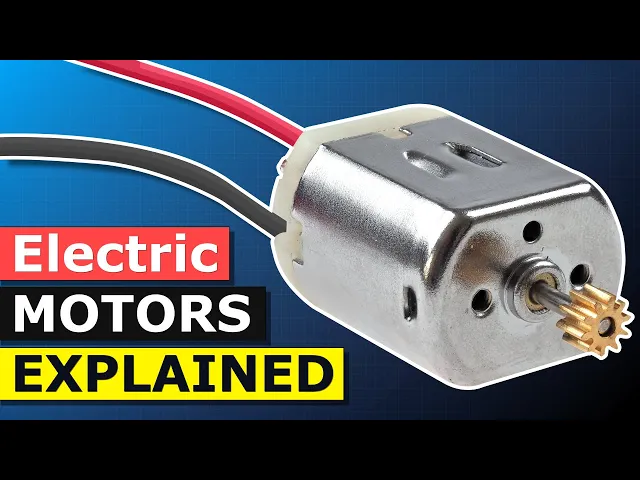
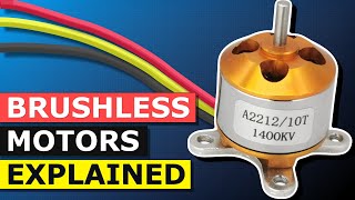
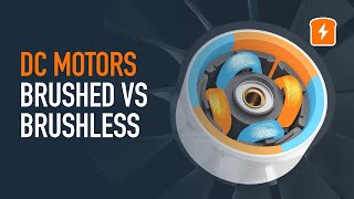
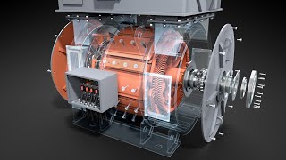
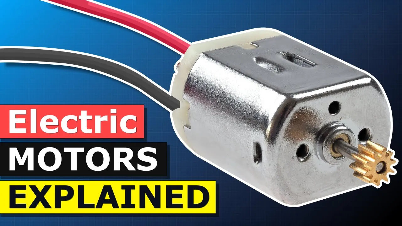
hey there guys Paul here from the engineering mindset calm in this video we're going to be looking at the DC motor to understand the basics of how it works DC motors look something like this although there are quite a few variations these are used to convert electrical energy into mechanical energy and we can use these for example in our power tools our toy cars and even our cooling fans when we look at a DC motor we first see the metal protective casing which forms the stator at one end we have the tip of a sharp
protruding through the casing we can attach gears fan blades or even pulleys onto this on the other end we have a plastic end cap with two terminals we can connect the power supply to these terminals to rotate the shark if we remove the casing to look inside the motor we first find two magnets inside these are permanent magnets which form a north and south pole running through the center of the motor we see this rod which is called the shaft the shaft is used to transfer mechanical energy attached to the shaft we have the rotor
the rotor is made from a number of disks which are laminated together each disk has these t-shaped arms cut into them wrapped around these t-shaped arms of the rotor or the coil windings which carry the electrical current from the battery as the current passes through the coils it produces an electromagnetic field we control the timing and the polarity of the magnetic field to create rotation the ends of the coils are connected to the commutator the commutator is a ring which has been segmented into a number of plates which sit concentric lis around the shaft these
plates are separated and electrically isolated from each other as well as the shaft the ends of each coil connect to a different commutator plate they do this to create a circuit and we'll see that in detail just shortly sitting within the plastic back cover are the brushes brush arms and terminals the commutator plates sit between the two brushes the brushes rub against the commutator segments to complete the circuit electricity can then flow through a terminal through the arm into the brush through a commutator segment into a coil then out to another commutator segment onto the
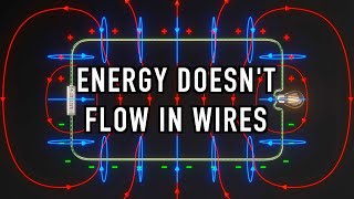
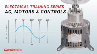
opposite brush and arm and back to the other terminal these components give us our basic DC motor to understand how the DC motor works we need to understand some fundamentals of electricity as well as how the components inside work but first where have you seen a DC motor used or where could you apply one let me know your thoughts and project ideas in the comment section down below electricity is the flow of electrons through a wire when lots of electrons flow in the same direction we call this current DC electricity means the electrons flow in
just a single direction from one terminal of a battery directly to the other if we reverse the battery then the current will flow in the opposite direction inside the copper wire we find copper atoms orbiting each atom we find free electrons these are called free electrons because they are free to move to other atoms they do naturally move to our atoms by themselves but this is in any and all directions at random which is of no use to us we need lots of electrons to flow in the same direction and we can do that by
applying a voltage voltage is like pressure and will force electrons to move electrons only flow in a complete circuit they always try to get back to their source so when we give them a path such as a wire they will flow through this even if we temporarily create a path they will take it as soon as it's available we can place components in this path so that they have to flow through it and that way they do work for us such as illuminating the lamp in these animations we're going to be using two terms that's
electron flow and conventional current electron flow is what's actually occurring with the electrons flowing from the negative terminal to the positive terminal conventional current moves in the opposite direction from positive to negative just be aware of the two terms and which one we're using as you probably already know magnets are polarized with north and south ends these types are known as permanent magnets because their magnetic field is always active when in proximity with another magnet the Lycans push away and the opposite ends attract so we get these pushing and pulling forces caused by the magnetic
field of the magnets magnets have these curved magnetic field lines which run from the North Pole to the South Pole and extend curving around the exterior the magnetic field is most powerful at the ends we see this because there are more magnetic fields closely packed together we can actually see the magnetic field of a magnet by sprinkling some iron filings over the top when two magnets are in close proximity to each other the magnetic fields interact too alike ends will repel each other and the magnetic field lines will not join however two opposite polarities will
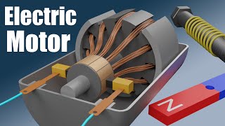
be attracted to each other and the magnetic field lines will converge into a highly concentrated region therefore we place tube magnets of opposite polarities into the motor stator to form a strong magnetic field through the rotor when we connect a wire to the positive and negative terminals of a battery a current of electrons will flow through the wire between the two terminals when electrons pass through the copper wire they generate an electromagnetic field around the wire we can actually see that by placing some magnets around the wire when we pass electricity through the wire the
magnets rotate when we reverse the direction of current the magnets will also reverse and align the opposite way so we can create a magnetic field which acts just like a permanent magnet except this type we are able to turn off the problem with the electromagnetic field and a wire is that it's quite weak but we can make it much stronger simply by wrapping the wires into a coil each wire still creates an electromagnetic field but they combine into a much larger and stronger magnetic field that's why we use these to create the coils around the
rotor if you find electromagnets interesting then check out our video on how to make a solenoid you can find links to that in the video description down below the coils of wire are known as windings the simplest DC motor has just a single coil these are a much simpler design the problem though is that they can align magnetically with jams the motor and stops it from rotating the more sets of coils we have the smoother the rotation will be this is especially useful for low-speed applications therefore we normally find at least three coils in a
rotor to ensure smooth rotation each coil is positioned 120 degrees from previous between each coil we find a commutator plate each coil is connected with two commutator plates the plates are electrically isolated from each other except that they are now connected via the coils so if we connect the positive and negative terminals to two of the commutator plates we can complete the circuit current will now flow and a magnetic field will generate in the coils the rotor or armature is made from multiple disks of iron which are laminated together each disk is electrically insulated from
one another with a lacquer coating if the armature was a single piece of solid metal large eddy currents would swirl around inside these are caused by induced electro-motive force or EMF s-- the eddy currents affect the efficiency of the motor to reduce the eddy currents engineers segment the rotor into insulated disks this way the eddy currents will still flow but they will be much smaller the thinner the disc the smaller the eddy currents will be the commutator consists of small copper plates which are mounted to the shaft each plate is electrically isolated from one another
as well as the shaft the end of each coil is connected to a different commutator plate in this design each commutator plate is connected with two coils the plates deliver electricity to the coils to get the electricity from the battery and into the plates we have some brushes which rub against the place the brush arms hold these in place when we complete the circuit electricity will flow into the commutator segments by the brushes and then it will flow into one or two coils as a path becomes available at certain points in the rotation the brushes
will come into contact with two plates this will create an arc and we get these small bursts of blue light as this occurs these arcs as well as friction will eventually destroy the brushes over time something we must understand is Fleming's left hand rule and for this we need to use our left hand in this funny shape you need to remember that Fleming's rule uses conventional current and does not use electron flow conventional current is from positive to negative we use Fleming's left hand rule to work out which direction the coil will push and pull
as electromagnetic field interacts with the magnetic field of the permanent magnet if we looks a wire and visualize which end is connected to the positive or negative we can work out the direction of force to do that stick your left hand out flat with your palm facing you think of these as being your thumb then fingers one two three and four first of all close fingers three and four point finger two to the right so it's perpendicular to your palm then point finger one straight ahead and point your thumb upwards your second finger points in
the direction of conventional current from positive to negative your first finger points in the direction of the permanent magnetic field from north to south your second finger will point in the direction of conventional current from positive to negative your farm will then point in the direction of force now I've made a PDF guide for this which includes some worked examples to help you remember it you can find links in the video description down below for how to get your copy so if we look at this example the conventional current is coming towards us and the
magnetic field is going from left to right so we point our second finger towards us and the first finger in the direction of the magnetic field our farm is therefore pointing upwards which means the force on the wire will move it upwards in this example we have the conventional current reversed in the wire so it's moving away from us therefore we flip our hand over so our second finger is pointing away from us our first finger still points in the direction of the magnetic field and our thumb points downward this means the force on the
wire will move it downwards if we wrap the wire into a coil how will the forces act now well we need to consider the coil as two halves on the left half the conventional current is flowing away from us so our hand flips and we see we get a downward force on the right side the conventional current is flowing towards us so the force is upward therefore we have a combined upward and downward force so the coil will rotate so now we can see how the motor rotates so let's have a look in detail okay
let's consider the operation of a DC motor in slow motion I'll just point out the main parts there's the north and south magnets which concentrate a magnetic field through the center in the center we find the shark attached to the shaft we have the rotor wrapped around the rotor we have the coils connecting the coils we have the commutator and providing power to the commutator we have the brushes and brush arms and finally we have a power supply the rotor coils and commutator are going to rotate everything else will remain stationary we are going to
be considering the flow of conventional current and the forces which are occurring in the long sides of each coil that's this side and this side will also label these coils one two and three and the commutator plates a b and c in this first position the conventional current will flow from the positive of the battery into plate a then through both coils one and three through plates b and c into the right brush and back to the battery the right side of coil one has a downward force and the left side has an upward force
coil three has an upward force on this side and a downward force on this side and therefore it rotates the current now flows through plate a and into coil one only then exits via plate B this creates an upward force on the left and a downward force on the right the current now flows through plates-a and c through coils one and two and into plate B coil one has an upward force on the left and a downward force on the right coil two has an upward force on the left and the downward on the right
the current now flows through plates II into coil to and into plate B the left side of coil 2 has an upward force and the right side has a downward force the current now flows through plate C into coil three and two and it exits wire plates a and B this gives us our upward and downward forces on the coils the current now flows through plate C into coil three then out through plate a creating our upward and downward forces the current now flows through plate C and B through coils two three and one and
out through plate a giving us our forces on each side the current now flows through plate B into coil one and out through plate a which creates our forces the current now flows through plate B and in two coils two and one it then exits via plate C and a the current now flows through plate B into quill - and then out through plate see the current now flows through plates B and a in into coils two and three and then out through plate see this then repeats again and again like so which gives us
our rotating force which we can use to drive things such as fans gears wheels and pulleys if we were to reverse the power supplier then we reverse the current and that will also reverse the forces and thus the direction of rotation okay guys that's it for this video but to continue your learning then check out one of the videos on screen now and I'll catch you there for the next lesson don't forget to follow us on Facebook Twitter Instagram LinkedIn as well as the engineering mindset calm