almost every industrial facility relies on the transfer of thermal energy to generate electricity control systems and working environments and even manufacture products so how do engineers control this that's what we'll be covering in this video which is kindly sponsored by super radiator coils one of the leaders in heat exchanger productions for commercial industrial and even nuclear markets all engineering design performance testing and manufacturing takes place in-house at one of their three divisions in chaska minnesota richmond virginia and phoenix arizona when it has to be perfect it has to be super for more information visit dot
superradiatorcoils.com and i'll leave a link for you in the video description down below a heat exchanger is simply a device used to transfer thermal energy between two fluids without them mixing fluids can be either a liquid or a gas or even a mixture of either of these take this oil for example we need to increase its temperature but we don't want to apply a flame directly to the storage unit instead we will boil some water and cycle this through a simple heat exchanger the oil is normally also cycled through the heat exchanger where it will
safely absorb the heat of the water the thermal energy is being transferred from the hot water through the metal wall and into the oil the water and oil never meet or mix they are always completely separated there must be a temperature difference for the heat to transfer and heat always flows from hot to cold we could also cool the oil down by pumping cold water through the heat exchanger the cold water will now absorb the thermal energy of the oil we see heat exchangers used everywhere from air conditioning units engine cooling radiators in cars and
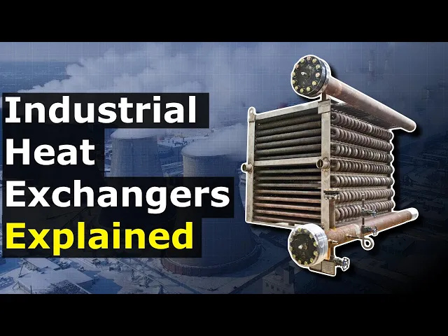
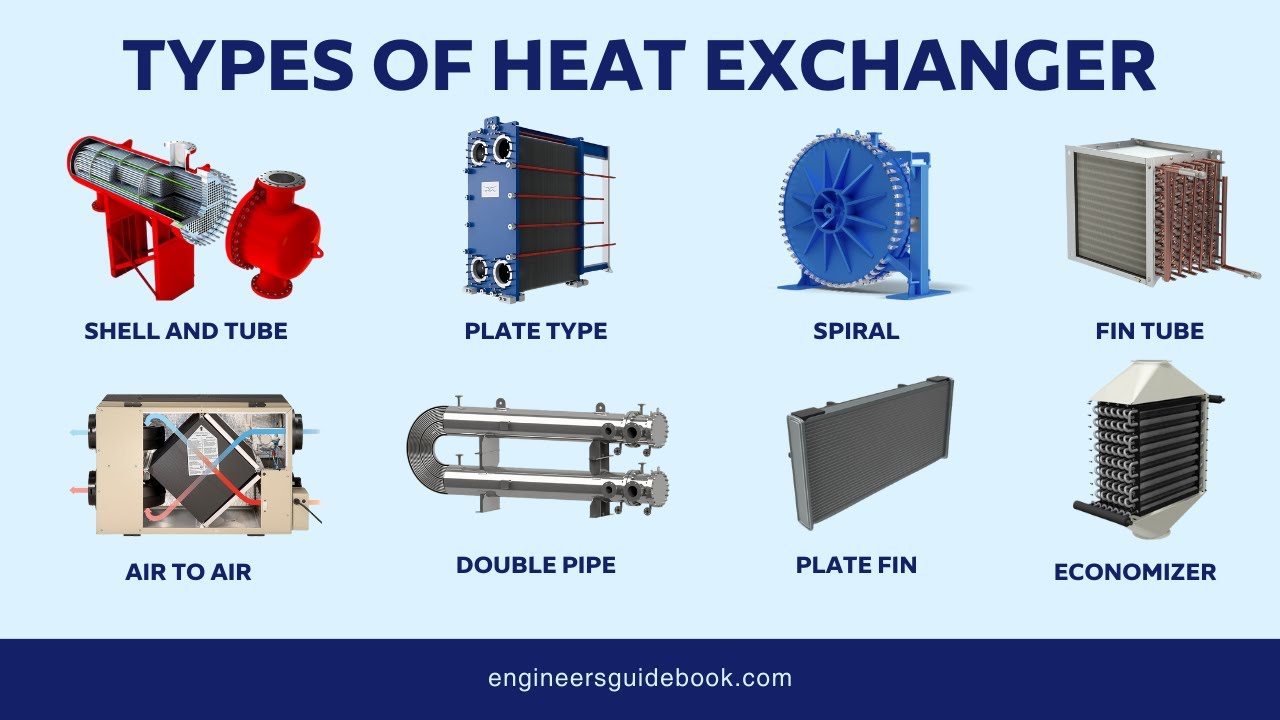
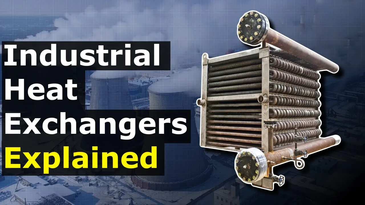
even on the back of refrigerators however industrial heat exchangers are a little different because they often work in extreme environments such as nuclear power stations oil refineries food processing plants and factories which all involve working in high pressure and high temperatures therefore these units are built sturdier and for more robust materials the working environments are often corrosive so they are chemically treated to handle this these heat exchangers will handle fluids such as water steam air refrigerants oil chemicals gases food products etc there are five main types of industrial heat exchangers although there are many variations
of each design let's look at a thin tube heat exchanger first which is probably the most common design used just before that i want you to tell me in the comments section where you've seen the different types of heat exchangers used and what for or what ideas you have for where to apply them a typical thin tube heat exchanger looks something like this we see there is an inlet and an outlet these are both usually located on the same end these connections are typically flanged but they could be threaded or soldered depending on the application
and the pressures of the working fluids running between the inlet and the outlet is a tube which will contain and direct one of the working fluids for example hot water the tubes will be covered with many thin sheets of metal known as fins the fins increase the surface area of the tube wall allowing more heat to transfer the other fluid for example ambient air will pass over the outside of this tube between the fins the two fluids will never mix the heat passes from the hot water through the tube wall and into the air the
heat of the water travels out through the pipe wall and into the fins the fins increase the surface area and allow more interaction with the airstream which improves the heat transfer in some designs the fluid will simply flow through the entire length of the tube other designs will have the fluid pass through multiple tubes at the same time these will be connected to a header at the inlet as well as the outlet to facilitate the distribution through the tubes for example these are used on a gas turbine power station to cool the intake air which
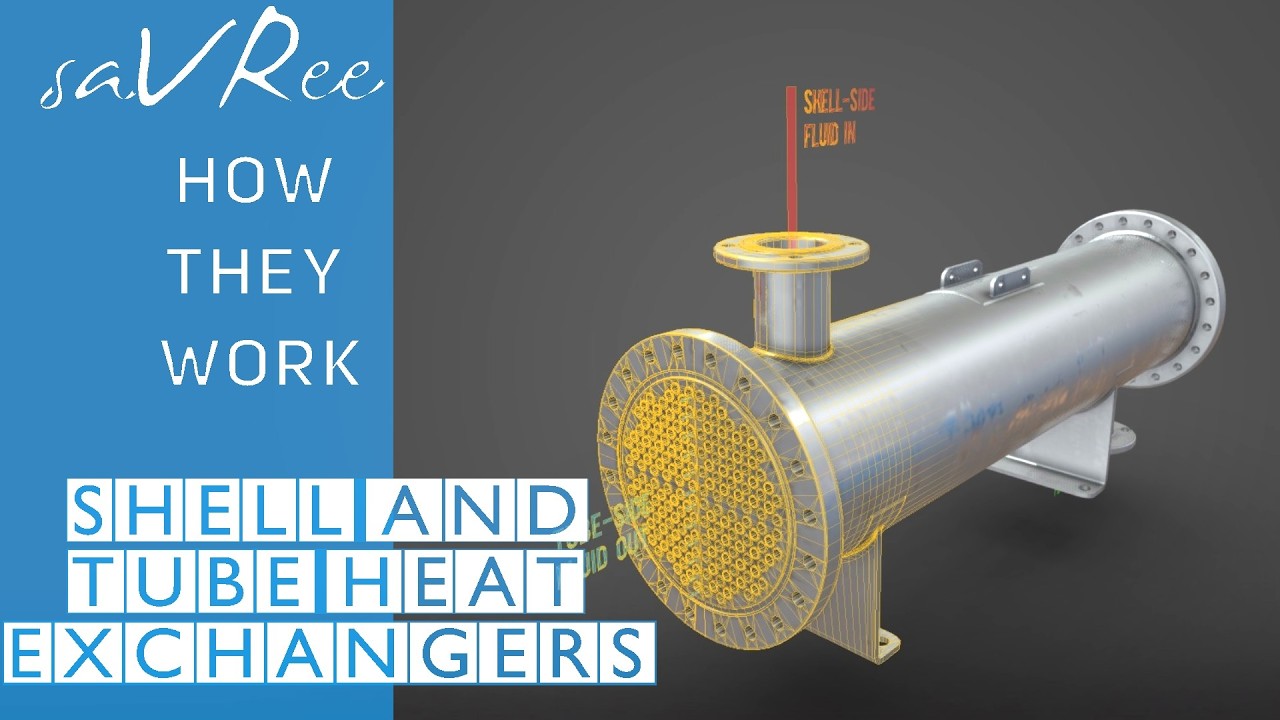
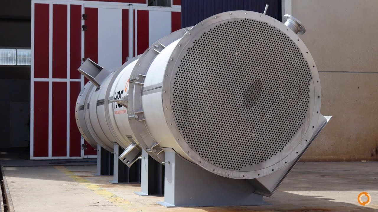
will be sucked into the turbine and combusted this helps the turbine run at optimal performance in hot and humid conditions a chiller pumps cold water to the heat exchanger which then flows through the tubes the warm ambient air passes over the outside of these tubes the thermal energy transfers from the hot air and into the cold water the air will leave cooler and enter the turbine the water leaves warmer and heads back to the chiller where the unwanted heat will be rejected back into the atmosphere shell and tube heat exchangers will look something like this
with this design we normally find the inlet and the outlet for one fluid at the very end of the heat exchanger known as the header then we have another inlet and outlet for fluid 2 on the main body known as the shell inside the unit we have the tubes these bend and loop around to start and finish at the tube plate which sits between the shell and the header the tubes will usually also pass through some baffles which are sheets of metal we will see how these work in just a moment the header as well
as the tubes can be removed for cleaning repairs and maintenance inside the header is a sheet of metal known as the divider or the partition this separates the tube ends enabling the fluid to flow into and then out of the heat exchanger tubes fluid 1 will flow through the header into and around the tubes then back to the header fluid 2 will enter the shell and surround the outside of the tubes the baffles will partially block the flow which will force the fluid to turn multiple times this creates a turbulent flow and ensures that fluid
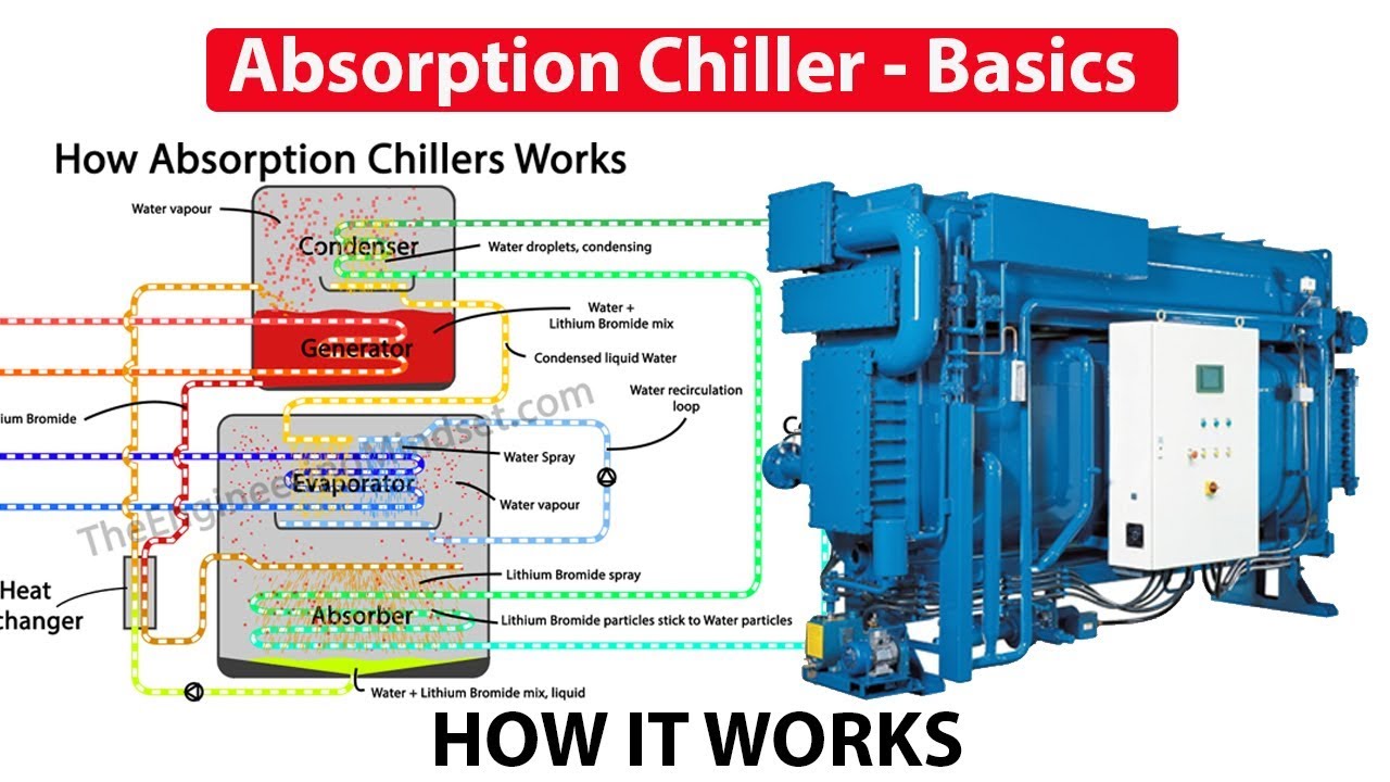
2 mixes with itself which ensures maximum heat transfer for example we might find this in a pharmaceutical factory with a boiler providing steam into the shell which surrounds the tubes a chemical product is then pumped through the tubes and this absorbs the heat of the steam through the tube wall so this product is going to exit the heat exchanger much warmer meanwhile the steam will start to condense into a liquid and flow back to the boiler to pick up more heat and repeat the cycle additionally these are used in refrigeration applications like this industrial chiller
we have the water flowing through the tubes then the hot refrigerant in the shell the water will absorb the heat of the refrigerant so that it can transport this to the cooling tower where it will be ejected into the atmosphere the water returns cooler to pick up more unwanted thermal energy from the chiller we have covered how chillers work in great detail previously do check those out i'll leave a link for you in the video description down below double pipe or tube in tube type heat exchangers will look something like this this is similar to
the shell and tube heat exchanger because essentially we just have a tube which runs back and forth a number of times between an inlet and an outlet this is surrounded by a shell which has another inlet and outlet a metal frame will hold the unit in place typically these will all be made from stainless steel one fluid will flow through the tube and another will flow through the shell the two fluids are separated by the tube wall and transfer thermal energy through this tube wall the different configurations result in different temperature profiles and heat transfer
in this design the bend at each end isn't utilized for heat transfer and heat can be wasted here however manufacturing this heat exchanger is cheaper and obviously easier other designs like this hairpin type heat exchanger which are often found in oil refineries will encapsulate the bend to fully utilize the surface area for heat transfer this version normally uses multiple tubes to maximize the surface area and thus increase the heat transfer although this will also increase the resistance these are a fairly simple heat exchanger design and are very common particularly in food processing as well as
pharmaceutical production for example we might have a dairy product flowing through the tube and then we have hot water or maybe even steam flowing in the opposite direction through the shell which will warm the product up to a certain temperature before it is mixed with some other ingredients and then bottled industrial plate heat exchangers look something like this they consist of a thick metal cover on the front as well as the rear of the unit which is typically made from mild steel there are two inlets and two outlets which are normally flange connections in most
designs we find all four ports located on the front plate as this allows the heat exchanger to be easily extended or reduced to accommodate a future change in operation most heat exchangers do not have this ability between the end covers we find a number of plates which are thin sheets of metal with a pattern stamped into them typically these will be made from stainless steel these patterns will help direct the fluids and create a very turbulent flow which increases the heat transfer between each of these plates is a seal known as a gasket this is
typically made from rubber these gaskets separate the plates creating a thin channel between them which fluid can then flow through on each plate the gasket will block two of the four ports meaning only one fluid can enter and exit the next plate will allow the second fluid to pass this alternates throughout the heat exchanger and keeps the two fluids completely separated only the thermal energy will flow through the sheets the entire unit is held together with some long bolts which compress the gaskets to form a very tight seal these heat exchangers are very common for
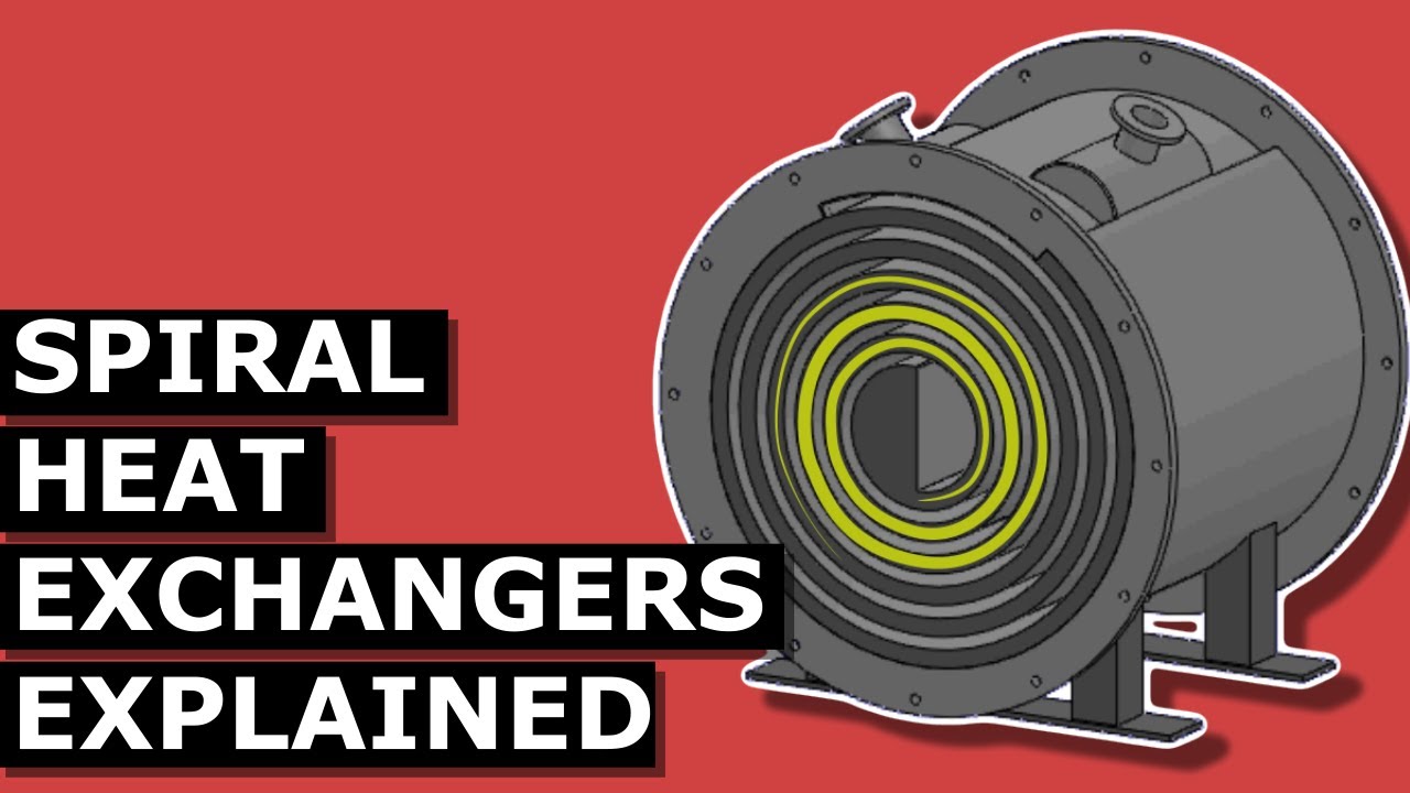
heating and cooling for example an incinerator power plant burns household waste to generate heat this creates steam which drives a turbine and generates electricity the waste thermal energy then passes through a plate heat exchanger to heat a district heating network and other buildings will then connect to this heat network also via a plate heat exchanger to supply their own heating demands this will be instead of them operating their own individual boiler spiral heat exchangers look something like this we have a flange inlet on the front face with the outlet located on the top then we
have an inlet from another fluid also on the top with the outlet located on the rear face behind the end plates we find two sheets of metal inside which spiral together around the interior to form a channel which the fluids will now flow through the channel completely separates the two fluids we see the first fluid enters the heat exchanger and fills the chamber then flows around the channel and to the outlet meanwhile on the other side the second fluid is entering via the top flowing around the channel and into the chamber where it then exits
the two fluids enter and exit at different temperatures this type of heat exchanger isn't as commonly used however because the design has only one channel for the fluid to flow through the velocity remains high making it harder for fouling to occur whereas plate and even tube heat exchangers divide the flow into multiple paths so these are ideal for installations where sludge like substances are processed for example in an anaerobic digester where the thick sludge is recirculated through a spiral heat exchanger to maintain a certain temperature this releases methane from the digester to power an engine
and then turn an electrical generator check out one of these videos to continue learning about mechanical and thermal engineering as this is the end of the video don't forget to follow us on facebook linkedin twitter instagram tick tock as well as the engineering mindset dot com