Hello friends welcome to engineering Funda family in this video I'll be discussing about waveguide attenuators with great clarity before I start with my explanation let me tell you how many points that I'm going to cover in this video first of all I'll be discussing about basics of waveguide attenuators after that I'll explain two categories of wave guide attenuators first one is fixed waveguide attenuators and second one is variable waveguide attenuators so let us begin this session with first agenda that is basics of waveguide attenuator first of all one should know what is attenuator the attenuator
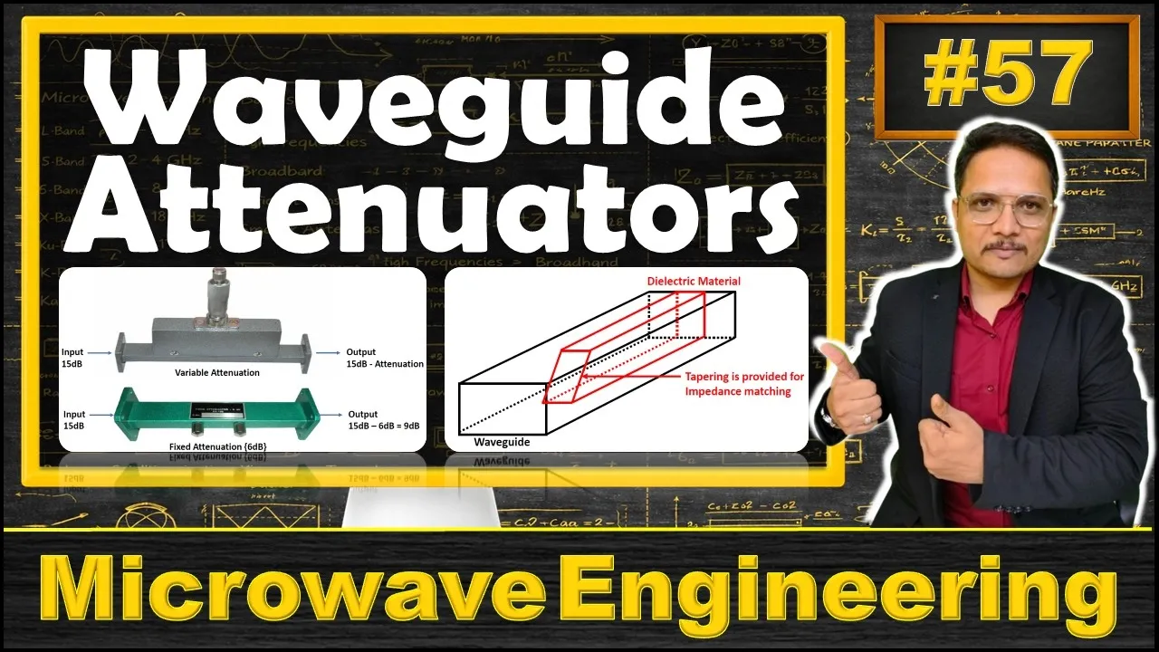
is attenuating input signal so but obviously at output side we'll be having lower power compared to input side and here we will not change waveform of input signal so without distorting input signal waveform at output side we will be lowering power so here attenuator does what it reduces power of input signal without appreciably distorting its waveforms let me take some examples probably you might have used this variable attenuator in your lab let us assume here we have input signal that is having power of 15 DB then at output side power will be 15 DB minus
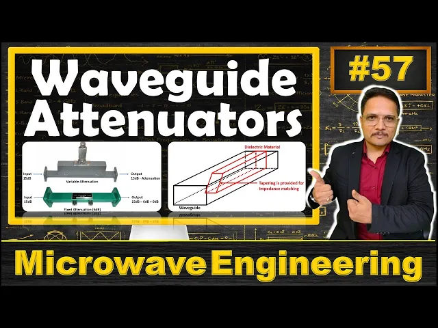
attenuation and here we have variable attenuator by changing this probe we can change attenuation value if I say here right now we have attenuation of 5 DB then at output side 15 minus 5 means 10 DB signal will be there and that signal will be having same waveform which is there at input side here we are not changing waveforms at output side right we are just attenuating input signal the second attenuator is fixed attenuator probably you might have used this attenuator in your lab as well this is of 6 DB attenuation whereas if input power
is of 15 DB then at output side power will be 15 - 6 means it will be of 9 DB so there are in general two categories of attenuators variable attenuator and fixed attenuator in fixed attenuator fixed amount of attenuation will happen in terms of DB it will be given to you in specification in variable attenuator by changing probe one can change attenuation right now I'll explain you fixed attenuators see in fixed attenuator attenuation amount will be fixed right like if you have 6 DB attenuator then whatever input signal that we insert at output side
power will be having lower by 6 DB value right like if you have input power with 10 DB then at output side you'll be having 4 DB power so fixed attenuator that we use it in circuit to lower the voltage to dissipate the power and it also improves impedance matching so basic agenda of fixed attenuator in circuit is to provide lowering of voltage it is also used to provide dissipation of power as well as it improves impedance matching in fixed attenuator we will be having dielectric slab which will be a glass slab coted with in
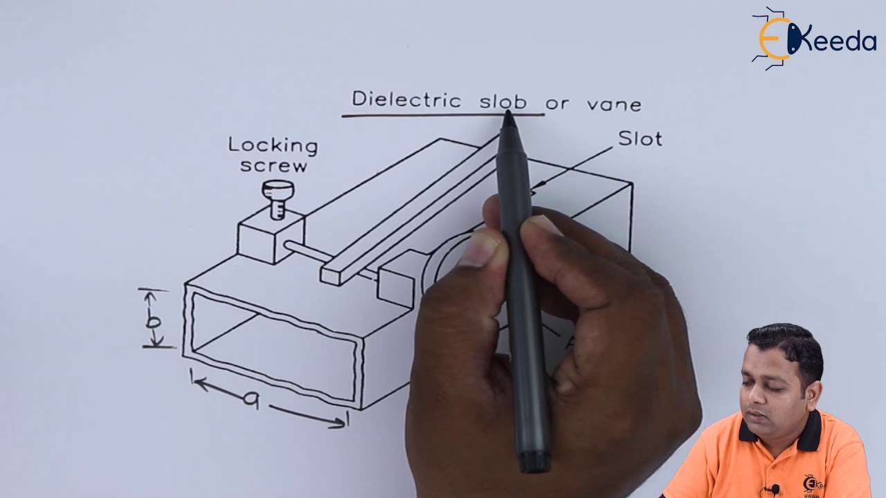
carbon film to absorb EM power in structure I'll show you how it is there right now consider in fixed attenuator we will be having dielectric slab fixed attenuators are commonly used where fixed amount of power is to be provided so as in when in circuit you need to have fixed amount of power at that time we use fixed attenuators right as if Entre power is getting absorbed in waveguide then one can say that attenuator is Terminator so as in when you use such Attenuator which is terminating entire power that is referred as Terminator right now
I'll show you structure of fixed attenuator if You observe here we have waveguide by black color one can observe we have waveguide and with this waveguide inside we have dielectric slab so by red color one can observe we have dielectric material inside this dielectric material that is a glass l coated with thin carbon film and that we use it to absorb EM power Here If You observe see at one end we are having tapping of that dielectric material that tapping is provided to have impedance matching so as I have told you fixed attenuator that is
having three basic agendas one is to lower the voltage second is to dissipate the power and third is to provide impedance matching so here by having this tapering we can improve we can optimize impedance matching of this fixed attenuator right now I'll discuss about variable attenuator if you talk about variable attenuator then but obviously here one can change attenuation constant usually attenuation constant that can be changed by wearing some parameters right I'll show you how one can change it by different types so variable attenuator that is providing variable attenuation here one can have continuous variable
attenuation or stepwise variable attenuation usually in rectangular waveguide we use lab type variable attenuator or when type variable attenuator and in circular wave guides we use rotary type variable attenuator now I'll explain these three categories with great clarity along with diagram let us discuss about flap type variable attenuator which we use it in rectangular wave guide If You observe the structure here we have rectangular wave guide and with this rectangular wave guide here we have dielectric material or one can say deipa paid or one can say resistive card so here we have resistive card this
resistive card that can be moved inside this rectangular wave guide by adjusting this knob so if you rotate this knob in this circular clockwise Direction then this dissipative paid that will go inside dielectric slab and as if it is going inside it will be increase attenuation inside this wave guide right so by changing knob by inserting knob inside wave guide we increase attenuation right so this is flap type variable attenuator which we usually use it in rectangular wave guide the second type that is when type in rectangular wave guide in when type rectangular variable attenuator
If You observe here we have movable when and here we have screw or movable knob that one can say If You observe by blue color we have movable when that is dielectric material if this movable wi that is there at Center at that time we will be having maximum attenuation and as if you move this when on side like you can observe here we have moved it on this side so here we have minimum attenuation so this is when type variable attenuator which we use it in rectangular wave guide by changing position of when we
can change attenuation at Center we have maximum attenuation and at side we have minimum attenuation that is how structure is there with movable when type attenuator right and third category is there with circular wave wave guide see with circular wave guide usually we have rotary type variable attenuator let me show that structure Over Here If You observe the structure here we have input here we have output and inside we have three resistive cards see this card number one and this card number two those are fixed resistive cards and those are oriented horizontally means it will
be having attenuation of signal with horizontally polarized wave with this card as well as with this card if You observe Center card so that is having rotation with this circular wave guide So based on the rotation of this resistive card which is there at Center we can Define attenuation constant let me explain how it will be attenuating so here right now consider we are transmitting vertically polarized d m w vertically polarized DM W now if resistive card that is vertically oriented then it will be resisting this vertically polarized EM wave with 100% amount but if
you rotate that resistive card now if you have angle right so if you have some angle then attenuation will decrease if it is there at 90° angle then minimum attenuation will be there and if it is vertically oriented at that time maximum attenuation will be there so here by rotating this Center resistive card in rotary type we can change attenuation so that is how different types of attenuators are there with microwave wave guides I hope you have enjoyed this session still if anything that I like to share just note it down in comment section I'll
be happy to help you thank you so much for watching this video