Hello everyone welcome to Instrumentation Academy In this video we will discuss some basics of control system First let's discuss what is a system? A system consists of three basic elements namely Input, Process and Output. The output is the specified function performed by the system.
The system itself produces the output as a result of an input being supplied to it. The system changes the input using a series of mechanical or chemical operation to produce an output. This series of actions is called the process Let's consider that a power source is connected to a bulb, then the bulb glows.
. This can be considered as a system now consider that we need to control the bulb that is it should be on when we require light which means we need to control, the output of the system according to our wish This is the simple block diagram of a control system. in this we can see two blocks, one is a controller block and the other is the system block.
In control system the input is given to a controller and the controller generates a control signal which is then forwarded to the system block. The system block receives the control signal and process it properly and finally gives the desired output. For effectively controlling a process we need to know how the input we are planning to use will affect the output of the process.
For this a mathematical model of relationship between the chosen input and the output of the process is made. The control system can be represented with a set of mathematical equations known as mathematical model These models are useful for analysis and design of control systems Analysis of a control system means finding the output when we know the input and the mathematical model design of control system means finding the mathematical model when we know the input and the output. most commonly used mathematical models are differential equation model, transfer function model and state space model Depending on the configuration there are mainly two types of control systems Open loop control system and Closed loop control system A system that does not have any feedback from output is known as open loop control system This is a block diagram of an open loop control system In this system based on the required output input is given to a controller and the controller generates a control signal.
This control signal is given as input to the process. Based on the control signal appropriate processing is done and the output is generated. Now the system assumes that this generated output is the desired output.
As there is no feedback path from output input is independent of output. so this system is also known as non-feedback system. As this system does not have any feedback from output the system cannot decide if the required output was attained or not.
open loop control system is also known as manual control system now let's see an example of open loop control system. A digital camera is used to take a photograph which is then transferred to a computer where processing of picture is done. now a printer is used to take a printout of this picture.
As there is no feedback from output no action can be taken to improve the quality of the picture. Closed loop control system. A system in which the controlling action of the controller is dependent on the output is known as a closed loop control system.
This is the block diagram of closed loop control system. This system has an error detector that produces an error signal which is the difference between the input and the feedback signal. This feedback signal is obtained from the output.
instead of direct input this error signal from the error detector is applied as input to the controller now the controller produces the control signal which controls the process. By this way the output of the control system is adjusted automatically till we get the desired output. hence open loop control systems are also called automatic control systems or feedback control systems.
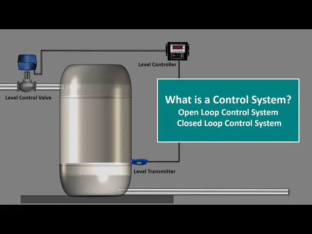
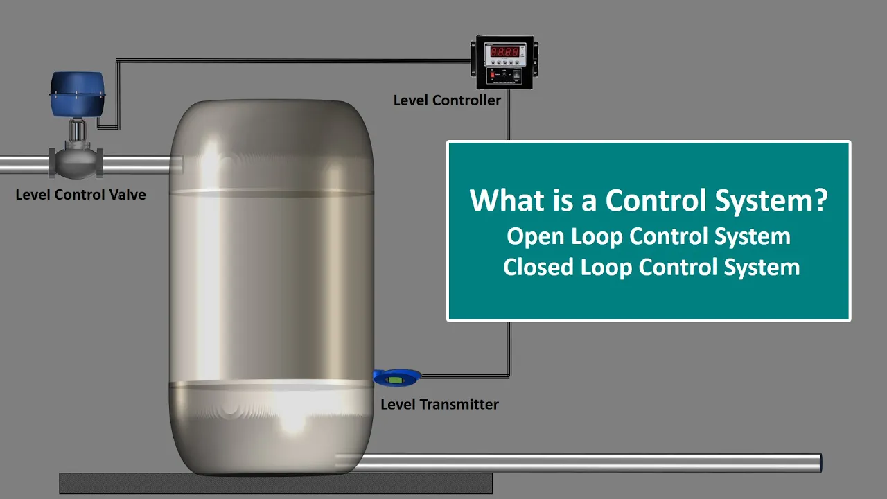
now let's see an example of closed loop control system. In this example a control system maintains water level in a storage tank. The system performs this task by continuously sensing the level of water in the tank using a level transmitter.
The output from the level transmitter is sent to a level controller the level controller then Compares this feedback signal with a desired tank level to produce the required control action that will position the level control valve as needed to maintain the desired level in the tank.