Hey friends, welcome to the YouTube channel ALL ABOUT ELECTRONICS. So, this is the introductory video on the digital electronics. And in this video, we will learn some of the basics of the digital electronics.
And in the upcoming series of videos, we will learn this digital electronics in detail. So, this digital electronics is a field of electronics which deals with the digital signals. That means the signals which is processed or generated using the electronic circuit are digital in nature.
So, these smartphones, personal computers, and many communication equipment which we are using in our day-to-day life are the example of it. On the other end, the analog electronics is a field of electronics which deals with the analog signals. So, the amplifiers, timing, and the wave-shaping circuits are the example of the analog circuits.
So before understanding this digital electronics, first we should be very clear about the analog signal and the digital signals. So this analog signal is a type of signal, whose amplitude can take any value in the given range. So the voice signal is the example of the analog signal.
Let's say, we are looking at the signal at the output of some amplifier which can take any value in the range of 0 to 10V. So in the given range, this signal can take any value. That means in the given range, there are infinite possibilities.
So such signal is called analog signal. Now in the time domain, this analog signal could be continuous or discrete. That means in the time domain, it may exist continuously or it may exist at the discrete time interval.
For example, the voice signal is the continuous analog signal. On the other end, if you measure the temperature of any CT at the interval of 1 hour, then it is the case of the discrete signal. But on the y-axis, this temperature can have any value in the given range.
But if you see the time scale, then in the time scale, it is the discrete signal. So that is the analog signal whose amplitude can take any value in the given range. And most of the naturally occurring signals are analog in nature.
For example, the voice signal or the temperature or the pressure which we are measuring are the example of the analog signals. On the other end, the digital signals are the one whose amplitude can take only finite values. For example, the signal which is shown over here varies only between the two values.
So it is the example of the digital signal. And in the time domain, this digital signal could be continuous or discrete. So virtually, all the modern digital circuits which we know are working on the two voltage levels.
One is the high voltage level, which is often referred as the logic high, and the second one is the low voltage level, which is often referred as the logic low. And since this type of digital circuits are working on only two discrete voltage levels, so the digital input and output of this type of circuit is often represented by the binary number system. For example, the logic high or the high voltage level can be represented by the binary one and the logic low or the low voltage level can be represented by the binary zero.
So in terms of the voltage level, the high voltage level could be a 5V and the low voltage level could be 0V. But in reality, the logic one and the logic zero are represented by the voltage range rather than the particular voltage level. For example, for any digital signal to be considered as logic one, it is not always necessary to be 5V.
And even if the voltage level is within a certain band, then also it can be considered as logic one. For example, if the voltage level of the signal is within 2V to 5V range, then also it can be considered as logic one. Similarly, let's say, if the signal level is within 0V to 0.
8V, then also it can be considered as logic zero. That means as far as the signal level is in a certain band, then it can be identified as either logic zero or the logic one. And that is the advantage of this digital system.
Because even if the noise or the interference gets superimposed on the actual signal, then also as far as the signal level is within a certain band, then it is possible to identify that signal as either logic zero or the logic one. So that is the one of the advantages of this digital system over the analog system. The other advantage of this digital system is that, the digital data is easy to store, replicate and process.
The same is not true with the analog system. Moreover, the digital systems are more accurate and reliable than the analog systems. And with the advancement in the fabrication technology over the years, the digital circuits are very much easy to fabricate and it is also possible to fabricate them in the larger density.
And compared to the analog system, these digital systems are relatively easily scalable. So these are some of the advantages of the digital system over the analog system. But the thing is, all the naturally occurring signals are analog in nature.
So if we want to process them in the digital domain, then first of all, we need to convert that analog signal into the digital signal. So using the analog to digital converter, it is possible to convert the analog signal into the digital signal. And then after, it can be processed using the digital circuits.
And if required, then using the digital to analog converter or the DAC, it can be converted back into the analog form. So this ADC and the DAC are also a very integral part of these digital systems. And in fact, on the channel, these ADCs and the DACs are already covered in detail.
So for more information, you can check this playlist on this ADC and the DAC. Now in these digital circuits, since the voltage level continuously switches between the high and the low levels, so they are also known as the switching circuits. And using these digital circuits, it is also possible to perform several logic operations, where the output is high or low based on certain logic conditions.
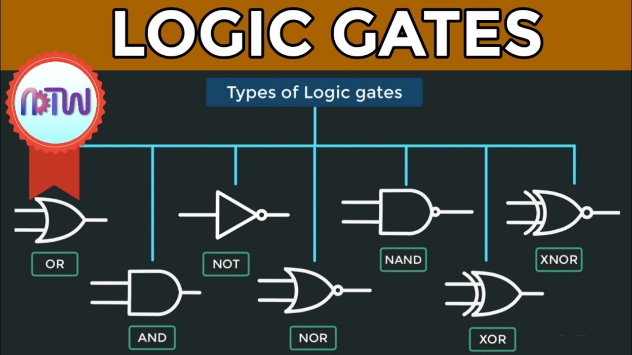
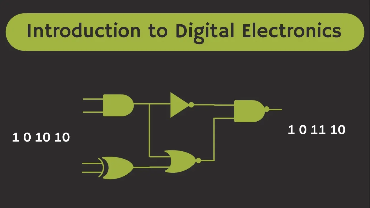
And therefore, they are also known as the logic circuits. For example, using this digital circuit, it is possible to design a circuit which will turn on the fan when it is daytime and whenever the temperature goes beyond 25 degrees. So the logic gates are the basic building block in the digital electronics.
And there are several types of logic gates. So this AND gate, NOT gate and OR gate are the three basic types of logic gates. And using these three gates, it is possible to implement any logic function.
Apart from that, there are two universal gates. And they are called universal gates because using any of these two gates alone, it is possible to perform or implement any logic operation. So apart from all these gates, there are two more gates, which are known as the XOR gate and the XNOR gate.
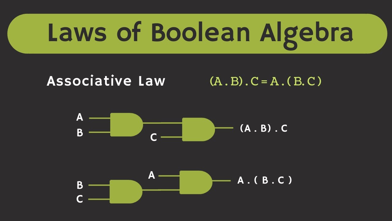
So using all these logic gates, it is possible to perform different logic operations. And any logic operation which can be implemented using these logic gates can be expressed using the Boolean expression. And using the Boolean algebra, it is possible to minimize the Boolean expression.
So this minimization of this Boolean expression is also a very important part in the digital circuits. Because with the minimization of this Boolean expression, it is possible to reduce the number of logic gates which is required to implement certain logic operations. So in the upcoming videos, we will learn more about these different logic gates.
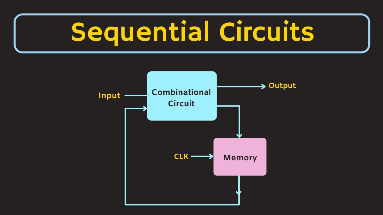
And we will see that, how these different functions can be implemented using these logic gates. Now in general, there are two types of digital circuits. That is the combinational circuit and the sequential circuit.
So these combinational circuits are the one where the output of the circuit only depends on the present input. While in case of the sequential circuits, the output of the circuit also depends on the present input as well as the past outputs. So we can say that these sequential circuits also have a memory element.
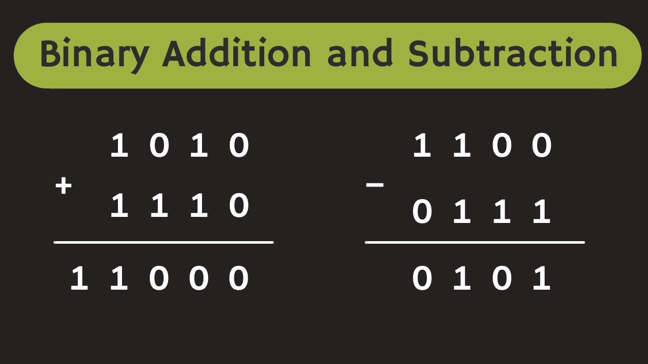
So this flip-flop is a very basic sequential circuit which can store one bit of information. And using these combinational and sequential circuits, it is possible to perform different logic operations. For example, the arithmetic operations like addition and subtraction can be performed using these digital circuits.
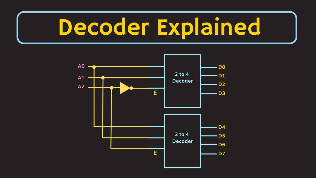
And the other operations are comparison, encoding and decoding, multiplexing and demultiplexing, storing and counting. So in the upcoming videos, we will learn about all these different digital circuits in detail. Alright, so now let's see the sequence in which we will study all these topics.
Now since the digital circuit deals with the binary inputs, so first of all, we will start with the binary number system and the binary codes. Then after, we will learn different logic gates and we will see that how the output of the logic gates can be expressed using the Boolean expression. And we will also learn a little bit about the Boolean algebra.
And we will see that using this Boolean algebra and the other technique, how we can minimize the logic functions. And after that, we will learn different combinational and sequential circuits which we have discussed earlier. And after that, we will also learn about the different logic families.
So although these logic gates are very basic elements of the digital circuits, but inside if you see, then it is the combination of different transistors. And there are different ways to construct these logic gates. So depending on how these logic gates are implemented, the different characteristics of the logic gate, like power consumption, switching speed and the voltage levels will change.
So in the upcoming series of videos, we will learn all these aspects. So that's it for this video, and I hope in this video, you got the basic overview of these digital circuits. So if you have any question or suggestion, then do let me know here in the comment section below.
If you like this video, hit the like button and subscribe the channel for more such videos.