Hi guys uh welcome back to Guru Tech networking training in this video we're going to do our Advanced Enterprise networking project 13 which is a cure company Network design and implementation okay all right so before we start I played with everyone who is joining me today remember this is a very important video as going to be a very long video the first thing that you'll do for me a favor actually please Subscribe to this channel like this video and share the same way we putting much effort we're spending a lot of time and hours recording
this projects editing them and delivering them into um a more effective way through which you can learn and gain some skills please please ensure you eat on the Subscribe button just like the video and say something on the comment section all right okay so with further Ado let's get into business all right so Secure company Network design and implementation actually guys this just an extension of one of the projects that we previously recorded and it was our project six so if you're new here today just know that we've been doing Enterprise networking projects from Project
one and today we're doing project 13th meaning we've done 12 projects that maybe you've not seen please please uh I'll show you how to get the projects just go to uh YouTube And search our Pro our Channel actually gur Tech networking training and the first thing that you do make sure you subscribe please support us after you subscribe just go under playlist after you've go to playlist and then um if you go to playlist uh then you can just um scroll till under playlist you just scroll uh till real world networking projects okay or uh
this one Enterprise Networking projects so when you click on that playlist actually you're going to receive a lot of projects you're going to see a lot of projects here actually you're going to see a lot of projects here that you recorded all along right okay so you can start from your project one watch till the 12 of project because these projects actually were are designed in a way that um the the complexity or the protocols or the knowledge uh uh being executed increases As the number of project increases so uh the comple the complexity of
project one is different with the complexity of project two and the same way complexity of project 13 is is different uh [Music] the channel membership it's uh it's not that much uh uh to pay for actually see the amount $1.49 yeah but the knowledge you get is much higher than that right okay all right so if you want to get the pocketer File of any project just join the channel membership and uh before you join the channel membership watch this video right okay all right so uh let's go back to uh packet a file let's
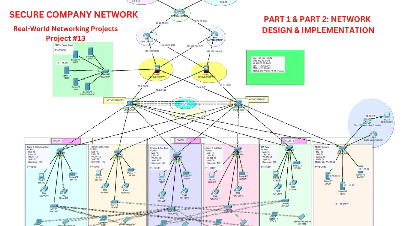
go let me just go back to our Channel and show you something yeah yeah so uh in the group Tech networking training there's a channel there's a video by the name uh the first video here company Network design and implementation so this is the video that We actually going to expand and make it look more professional okay all right so it was recorded one year ago actually and it has uh 130 views okay all right so uh I'll just um minimize this and uh open this um uh for uh picture here yeah so uh this
is the project that we're going to modify and make it look uh Advanced actually so in this project in this project as you can see we had um uh two isps okay then the IP connects to the routers so these were the the first modifications uh the first modification will actually come in instead of the routers we're going to use firewalls okay yeah then the M layer switch will stay the way they are the access layer switches will stay the way they the way they are then when you come to access points the well has
access points here We going to use wireless land controller and this access point we are going to be a lightweight access point manage by the wireless landar controller and we're also going to add IP fonts in this setup all right and in this setup we're going to have because we have the firewall you're going to have zones the DMC Zone connected to the firewall where the servers are going to be located the inside Zone where the users are and uh the outside zones where the All right it's going to be very uh Advanced project okay
so I just ask for your patient because um these types of videos normally takes a lot of time maybe 3 hours okay but it's worth it just dedicate your time watch the video to the fullest and you'll gar a lot yeah all right so I'll just minimize this and open the case study secure company Network design and implementation solutions to clients Worldwide leveraging cutting Ed technology and a team of Highly skilled professional C Innovation focuses on developing and implementing cloud-based solution tailored to meet the evolving needs of businesses across various industry with a strong emphasis
on creativity agility and customer centricity certain Innovation a to empower organization to enhance their operational efficiency scalability and competitiveness in today's digital Landscape with a work with a Workforce of 600 staff set inovation limited recently expanded and is preparing to move to a new building the new building comprising three floors will house various departments including sales and marketing uh human resource and Logistics finance and accounts administrators and public relationships ICT and ser the ICT Department further H software developers Cloud Engineers subscript Engineers Network Engineers System administrators it support Specialists business analyst and project managers prior
to the move a new network service needs to be designed and implemented in the new building to ensure repass Security saton will Implement several security measures to protect the network from internal and external attacks the fire will will have Outside Inside and the DMZ security zones the essential servers strategically hosted Within the Fortified Zone additionally active directed to server responsible for managing um and authenticating users computers and resources within the internal network will be placed on the inside zone of the fou this implies that the server such as DP DNS radius will all be on
the inside Zone while the while other server such as FTP web email app and N storage will be located in the DMZ The Zone can be attached to to any firewall as of now this meticulous Planning and deployment of security measures will will sard the network and ensure smooth operation for certain Innovation lab uh I mean certain Innovation Limited in its new building yeah so as an integral part of a city infrastructure the following components have been Incorporated in a service provider um the company actually that should be the company the company has established a
subscription to with the two isps ccom And safaricom to ensure internet connectivity network security two uh s firewall Cisco s firewall uh have been deployed to uh enhance network security and rancy network Crow both the FI and the cor switches will be used instead of the router Network switching the network include the network includes uh two Catalyst Cisco I mean two Catalyst 3850 uh 48 Port switches and Catalyst this one 48 Port switches to ensure Robust local network connectivity server hardware and virtualization two physical servers will be uh utilized for virtualization through provisor to achieve
multiple virtual machines for various Services Wireless infrastructure a Cisco Wireless Lear controller and various lwe access points will centralize the management of wireless network VI a Cisco voice Gateway will be used to enable telephone service in the network Cloud computing as an important technology is used to connect clients across the world world to the company services and resources that the proposed Network should should allow the team to access the resources all right therefore as a key member of network team you've been tasked to design a network for the new building at this stage the local
is is required which shows the measures that you would put in place to ensure that the new network Meets the current business needs and its future proofed good so let's go to requirement let's go to the requirement now here so the requirements the company places a strong emphasis on the achieving top TR performance rcy scalability and availability within its Network infrastructure as such your task involves creating a comprehensive Network design and executing its implementation to facilitate this Endeavor the company as designed uh as designated specific IP address ranges yeah so you're going to have a
management Network having that one we're going to have a wean having that one we going to have a lan that one VI that one DMZ that one public IP addresses uh yeah that one so uh let's go to technical requirements now technical Tech requirements utilize Cisco Peta as a design tool let's Embrace IAL Network design ISP you're going to have two SP yeah then you're going to have a wireless land controller to manage the lightweight access points okay we're going to have how many villain we're going to have four villain 10 for management 20 for
land 50 for whe uh 70 for Vi and 199 for black hole in which all unused sports are placed then we go to either Channel you're going to Agate uh links to form One logical Channel telepone service we want to configure a VI on The Voice Gateway and locate D numbers in the format of four dot dot STP portfast and BP to use this one uh to fasten or to expediate Port transition from blocking to forwarding States subna subna is very important we're going to do subing actually to allocate appropriate IP addresses to the uh
to each group yeah a basic configuration very important we're doing all this basic configuration Dev Routing is very important we to do routing to neor Vance to communicate then the co switch the co switch you know we don't have a router so the C should be used for switching and routing so we need to assign it IP address okay so the gcp will be used to allocate Dynamic IP address to the host to computers in the network all right hsrp very important hsrp you know it's a high avability router protocol okay all right So uh
that's going to be implemented static IP addressing you're going to do static IP addressing to the servers okay routing protocol well we normally use SPF as our routing protocol because SPF this is one of the standard um and the best routing protocol Dynamic routing protocol okay all right so we can I don't want to use eigrp because you know eigrp is normally a Cisco proprietary I don't want to use rap because SPF is way much better than RP okay all right and Uh maybe bgp will use bgp in the next projects when you're going to
do ISP networks okay all right but for now you're going to Usef standard for SSH remember we we have management Network so uh to manage the Dives we're going to do SSH and we're going to limit only certain people to SSH on those devices that's why we're going to do standard Access Control list for SS Cisco firewall very important you're going to do a lot of Configuration on The Cisco firewall yeah then the final stage is test Tes in to ensure that whatever we configured is actually working all right so guys basically when I when
I analyze this case study I I realized that the company actually wants to move to a new building and they want to uh design a new network to support the users actually and there are some key points that come to to to me actually we have two files right okay then there was something Mentioned here the DMZ zone for the first time we going we're not going to put DCP DNS and the D radio server on the DMZ zone why because the dscp uh the active directory server here will act as our DCP server but
the active directory server it's always a good practice to put the active directory server in the inside Zone because it the in it is the active directory server is that will be used for managing and Authenticating users computers and resources so for the DP DNS and radius servers you're going to put them in the inside Zone but the rest of servers they're going to be on them sorry for the DCP DNS and radius we're going to put them in the inside Zone but the rest of the servers they're going to be in the DMZ zone
right okay all right so guys as we said that it's this project that we going to modify we have Two SP we have two two routers here but now we're going to replace with firewall then we have here we have actually um the two mules so with any further hard to I'll just start uh the design part all right okay so when I come on the here what I need first I need two routers to act as our as good so I'll just in this case I'll just take a 2911 route and put them somewhere
here those are our ISP this will be our isp1 ISP 2 okay then we need two fire Walls okay we need two fire we for the fire we going to choose 5506 just put two Firs there once we have two firewalls now let's go to the multi layer switches for the mul layer switches for the mul layer switches we going to choose we going to choose 3650 okay we going to choose 3650 mulay switches okay all right so and then how many we had remember we had uh three Floors we had three floors here we
had three floors all right and the first floor let's assume the first floor will contain sales Marketing sales and marketing plus human resource and Logistics okay so let's put a representative there in regards to switch so let's just assume that that will be our sales and marketing switch then this will be our human resource and logistic switch okay okay then in the second floor let's Assume we add finance and accounts plus admin and public relationship so we need also two switches there for um for finance and accounts and then um we need one for public
relationship and admin yeah then finally on the on on the on the third floor actually we had a i City Department and the server room so remember City Department is so big because it contains a lot of users okay yeah so we just going to represent it with one switch actually we just going to present it with the r switch so let's assume that will be our department there and finally we'll have our uh server remember we going to have a two locations where we put our servers On this design one will be insert the
other one will be the DMZ so let's assume that this is our in inside server Zone where we going to put the DP DNS and radius okay but the DMZ server Zone will be attached to the firewall here okay all right so don't worry about that thing the active directory server must should always be in the inside Zone okay yes so guys as you can see we have the required um Network networking Devices we have the is P the fire the two firewalls the two M switches and uh the six uh access layer switches and
uh the the second thing that I'll do I'll do the connection so to do to do the connection we normally start from the top okay and in this case just use automatic cable type and start from the top going down okay so as you can see we've made uh the connection between the networking Devices you can see we have R see all over the network yeah and uh one thing that I would like to mention also we need to connect the two layer switches to implement uh uh either channel so just connect them yeah so
we have three so we have three uh cable connection between the two MERS just good so we have a n of in this network as you can see it's going to be a very beautiful uh Network design just like uh uh the pre are here okay so this One serves as a degree or diploma diploma project but the one that we designing actually this a master's project okay it's a very Advanced project all right okay so uh the uh the next step is just to um include now uh the host devices plus other uh devices
actually so for the host devices we normally require just a computer for testing a department should have a printer for Printing then we need a a VI actually you're going to choose the first IP phone we need a VI need a VI phone yeah just one V phone can be enough or we just use two yes just need two let's just in this case used to right okay we need a print PC for testing VI Phone and access points plus wireless devices for the wireless devices uh we need a laptop remember users will be using
laptops we need a tablet many people have tablets then a smartphone actually very important then now let's put in the uh the lap which is lightweight access point so for that one you just come networking devices wireless devices then choose uh this one this lap PT okay so that lap PC PT we going to manage it Using uh wireless land controller right good so that's this is this network okay so uh the next thing I do I just want to turn them on just uh click them under the physical tab drag IP phone power adapter
and place it there same applies this one then for the L access point also they have they have to turn them on just drag the power adapter and put it there and finally for the laptop we going to remove um uh EET adapter or slot and put Put Wireless slot so remember this this is just EET uh slot so just turn the laptop off first then remove this this slot there and drag this WPC there then put it there then turn it on again so we done the next step let's just connect them very very
fast good so after we made the connection after we' made the connection now we can just do this one just copy that way just Mark that way And just contrl C and crl V then the way that they just marked just drag them oops so I have to yeah I have to undo and copy again crl Ctrl V then the way that just marked then drag yes so I'll do that and connect them very very fast save time okay guys so as you can see actually I've connected all the host devices uh in all this
department except the last switch which we say that we're going to Connect uh the servers so on the last switch I want to say that we're going to connect servers and the controllers so the controllers are like voice Gateway and the wireless landar controller so I'll need how many servers three servers one for DP DNS and the radius server yeah so we have three servers there then I need controllers the wireless learn Controller Plus voice Gateway for Vi right all the all of them will be placed on this switch here good So I just need
Wireless Lear controller just come to wireless deves then choose this one 254 and now I'll just place them somewhere here not below there because to differentiate them from the rest of the hosts okay all right so I also need to VIP so for vipe I need 281 router just scroll to the last one 28 11 router strictly choose 281 router I repeat strictly choose 281 router good so this one will be um for wireless land Controller and remember when you're going to implement V Ure that this we this v l controller is in the same
Vine with all the access point you're going to implement VI ens sure that this voice Gateway is in the same Vine with the IP phones okay all so let's connect them very very fast okay so uh that's done actually so we've connected all the required devices all right so the only part that is made is connecting the DMZ zone so for the DMZ Zone we were told here that the DMZ The Zone can be attached to any file as of now being that you have two files and I don't want to make this configuration uh
complicated let's just attach the DMZ Zone to only one file so in this case I'll chose this fire all okay so for that one I just take a Cisco access switch all right right I'll just take that switch and put servers so I'll need at least four Servers so actually on this uh design it's only on the DMZ that we have a single point of failure so you can see on the DMZ we've not implemented ly okay so when this cable Cuts or even this switch is down or the fou then the DMZ resources cannot
be accessed that's why I'm saying in the next video uh we're going to uh I don't want to connect this switch to the this firew again okay because of the complexity of this design if I'm forced to connect it then I'll be Forced to include a layer three device in between them okay but I don't want to uh to make it more complex so in the next video in the next project actually I promise whenever we have two firewall then you're going to implement ay for the DMZ Zone okay all right but as for now
let's just connect it to one firewall right okay good so uh the next thing uh we said that um we said that actually the um the main Objective of this design is to enable uh uh this is a cloud company a Cloud solution company then it should connect the clients outside or globally thus we should have an aspect of cloud right okay so to include a cloud here actually I'm just going to use um kind of a router then uh bundle it into Cloud right okay so I'll just click on the router so I'll just
take 291 router to be our Cloud router okay then remember we want To connect some users to the cloud so to connect them let's just assume that they a virtual switch somewhere right okay all right then we need two users one maybe in this a Kenyan company so let's assume the one is in uh one is in the USA another one is in uh China actually yeah so I connect them yep so uh this is our Cloud remember this is our Cloud so let's just assume these users are connect we don't Know how they are
connected but we just want to represent that they connected so this should be our Cloud so I just iight them mark them that way then include this Cloud thing okay so that's our cloud or Internet actually you can name it internet or Cloud yeah so whenever we going to implement when we are going to actually uh when we are going to configure this the insert devices we Just going to click click that inser that uh cluster and we configur all and go back or you can just um we can just grab this thing this delete
thing okay just grab that delete thing and come and click there once and un cluster then we configure after we finish configuring everything we mark them and bundle it again right okay so the next thing actually you can see this a very uh nice project very nice project so the next thing that we're going to do Here actually guys is to name the devices which is very very important in our Network design implementation uh we normally ensure that all the devices in the network are named appropriately okay all right so I'll just do that very
very fast to save time okay guys so I've managed to name all the devices in the network and Uh the second thing that I'll do I I mean the next thing that I'll do now is to uh separate the borders and give a background um color to each department or each segment okay all right so for that I'll also do it very very fast save time so I believe these are things that you've been doing actually so just a repetition of what we've been doing okay guys so uh as you can see we've Done uh
background decoration and now our design is looking uh very beautiful as you can see yeah so I've separated the borders for the Department the floors etc etc so what's meaning here it just a little bit of comments a little bit of comments uh which shall do very very fast also to save time okay so uh as you can see I've done the Namings uh I mean the namings plus the comments that are necessary uh so if I can just explain a little bit of the comments you can see this are sales department and it will
have several Vance V 10 management 204 L 54 whe 74 vipe and finally uh 199 for black hole and all the IP address is going to be via DP okay all right so another thing that I need to mention here let me just see so before we go to to implementation part let me just see Which I can add okay so uh we done with the first part of uh Network topology design where we've designed this uh beautiful topology uh the secure company Network system design and uh implementation so in this second part actually we're
going to do we're going to start on the implementation part so uh this one these config guide is what is going to guide us on what to be added on Each uh device or component in this topology right okay so uh we're in the Second Step which is the basic settings to all devices plus SSH plus standard Access Control list for SS so here we're going to do a are basic settings to all the device and add S Plus standard for S so for the only devices that we're going to do are the basic settings
the only devic that we're going to uh cover in step two which is number one here are From the mul layer switches going down okay and also the DMZ switch I'm not going to to configure basic settings on the firewall on the firewall we going the firewall is the last thing that we going to do so as for now we not going to touch firewall because um I would like us to uh get better understanding of the firewall step by step okay so the the firewall is the last thing that you're going to do okay
so for the basic settings I'm just going to do this DMZ Switch then from the cor switches going down okay and we're going to add uh SSH plus standard for S the standard will uh will only allow the management Network to remotely access the devices okay you're going to create an access control list a rule that only allow management Network to manage the networking devices all other networks will be denied okay all right good so as our culture we normally configure one device okay step by step all right then we Write commands on notepad and
copy paste to all other remaining devices okay very fast save time so for demonstrating purposes I'll just start with this uh sales and marketing switch okay all right so I just click on the sales and marketing switch right okay then we come to CLI enable and config T good so among the basic settings that we're going to configure here you can See on the on the case study we were told to configure just a minute here is the case the basic settings yeah here we're going to configure host name console passwords enable password Banner messages
password incription and we're going to disable a domain lookup okay all right and most importantly we should not forget username and password okay okay all right so uh let's just go back to so we start host Name host name to be these are sales and marketing switch I just name it SM switch good then L console password we just say Lan console L console zero okay then you just say password to be you write something anything but in my case I always like you see Cisco just for demonstrating demonstration purposes okay but in your case
use a very strong password okay all right so line console zero password Cisco then login whenever someone enters This this uh parameter online console as the password then they should be authenticated and they should be loging okay good all right so another important thing that I want to include here is uh actually login synchronus and exact time out okay so uh after some time of inactivity uh the user should be uh logged out automatically okay so exact timeout exact timeout to be 3 minutes 0 seconds okay then login synchronize to prevent unnecessary logs From disrupting
our configuration login synchronous and you just hit enter and exit the L console good all right so we to enable password just set enable password to be um Cisco I just use everything as Cisco okay good so another thing that we going to configure is um Banner messages uh password incription and they P domain look up okay so Banner motd Banner message of the day motd okay then you write any any character I'll write uh that hand Character okay then come back inside that character and you just say any message maybe you have to give
a warning no unauthorized access no un unauthorized access okay good and you just hit enter right so another thing that we want to do is uh um uh dis IP domain lookup just say no IP domain Domain look up and E enter good so the last thing here is um password encryption well all of these passwords the way we've configured them if you can just uh show the running configuration or the Startup configuration you will see them in plain text so it's someone can easily uh extract our password and uh maybe compromise our devices uh
when we not aware so to turn this password into Andre and readable format just say uh uh Service password encryption yeah so that command will encrypt everything all right good all right so uh We've configured several um several um basic settings on this switch so we need to do a search plus AC for SSH okay all right so to configure SSH there are some basic settings that you have to configure all right so the first thing is called um username and password we have to configure username And password that uh a remote user will use
to access the devices so just say user username I just use Cisco password to be Cisco all right and E enter and also the most important thing is uh IP domain name right the switch or the device should have domain name just say IP domain name to be cisco.com just want to use Cisco for everything Okay IP domain name can be cisco.com okay all right good all right so after you've configured the uh the username and password plus IP domain name now you can generate crypto key so just say Krypto key generate RSA uh General
Keys modulus length to be 1024 okay and just hit enter good all right so we've generated the crypto keys and you can see it will uh the name of the will be the name of the key will be SS sm. cisco.com okay all Right so let's enable SSH just say IP SSH version two good so we've configured s but we've not um we've not uh appended the SS configuration on the v2i interface so remember vty interface it's that interface that the remote user uh uses to to remotely access the device so you have to append
the SSH setting on that interface so just say line vty 0 to 15 just want to use 0 15 okay and just say login login loal that means it will use the username and password that I've Just created okay local database good then transport input SS we only want uh remote access to open via SSH remember there are two methods here tet or S tet is not secure s is secure so we want only to open for SS okay and just hit enter exit and do right okay so uh let's do the uh access control
is for SS to allow only the management Network to Access um to access uh the devices remote okay all right so uh just say access list access list uh we can name it anything even one then permit permit the management Network so the management Network here was uh this one one and two 168 10 is 1 Z yeah so the network is 1 2 1681 0.0 then um The W MK 0.0.0 255 okay all right so let's deny any Other IP from accessing access list X access list access list one deny uh query any now
yeah all right so we've created an access rule actually Access Control rule to only allow the management Network and that access rule will also deny any other network so let's append this access rule on the V interface because it's a v interface that we want people To access uh to use for a remote access okay all right so we have to append it on the V2 interface all right okay so we have to append this rule on the vti interface so just say line vty vty 0 to 15 access access uh class one it's access
class one right the number is one then in let's quy yeah that's all access class one in yep that's just exit and do right so we've done with the basic configuration On the switch so let's do now let's uh write commands on the notepad and copy paste to all of the remaining switches okay you're not going to touch F we don't have root oh we have we have routers actually we have this router but we don't need to configure um basic settings here okay all right so I'll just do uh the mod layer switches and
this access layer switches okay all right so when I open notepad actually uh New tab so let's start writing commands the first command is uh host name uh it's always enabl then config T all right then host name uh in this case it will be it will be this switch hrl and logistic all right HR and uh logistic switch good and then uh we go to line console line console Z the way the way we did here just follow this one you go To line console Z then you set a password just say password password
to be Cisco okay and uh I really ask you I ask you guys to be very careful when configuring the uh when writing on the notepad because when you miss something uh it's Cas sensitive you are doomed okay so just ensure that uh you write a correct word okay good so password is Cisco then log in the user authenticate the user then login synchronus to prevent un necessary logs From interrupting our uh um configuration okay login synchronize yeah yeah ens sure you've uh you're writing correct English exec exec timeout such that uh exact time out
yeah such that um when we I when we we are idle for maybe 3 minutes uh we being logged out and we required to log in again then exit actually so we are done with the that's line console now let's go To enable password and BD so just say enable uh password password to be Cisco everything this is good then uh this one now uh B I just copy this sorry B I'll just copy this message here yep so maybe to give a warning yep and now IP no IP domain lookup no IP domain Lookup
good yeah then we go to service password encryption to encrypt the password service password encryption password it's one word I'm sure it's a correct English yep all right so it's like we done with the uh some of the basic settings that we're doing now let's go to S configuration for S configuration we have to configure username and password so Username username to be Cisco password to be Cisco okay all right then uh uh of course you have to give it a domain name IP domain name to basis.com all right good then uh after we we've
done the settings now let's create uh generate the crypto Keys just say crypto I just copy this command crypto key generate RSA General Keys mod the length to be 1024 yeah good and I paste there then now near SSH IP SSH version two good then um now let's put the SS configuration on the V2 interface on the V interface yep so okay so just say line V2 0 to 15 uh login local to use the local database okay uh then transport trans transport Input SSH we want we only want a SE to be used as
a method of remote access good and then uh we just done there exit so uh a SE has been pended on the vtu interface so whenever you want to remotely access the device you have to strictly use SSH and you have to use the local database which are username and password good so another thing that you have to configure here finally it's uh it's Access Control list for SS Because we want only the management Network to remotely manage these devices okay so just create that rule of which I've created on this side Access Control list
one permit only management Network okay then the same Access Control list should deny any other IP deny any any other IP good that's all yeah then now let's append this rule on this interface okay right so I just copy that that h no no no I just copy this One only good then uh PR it there and I say access access access uh list access class now access class one to get inside then exit and finally do right wow so we're done with uh with writing uh the commands on the notepad so what's me is
just to copy paste on all other remaining switches so when we go to each switch what you're going to modify is only name because uh these switches have different host names right okay so that's only what we're going to Modify as per now we're just going to modify H name of the switch everything will remain the same okay all right so let me just confirm if uh there's uh any grammatical error here I can't see so let's test on on let's just test this on HR and logistic switch fast if everything is okay then I'll
just proceed very very fast no no no just paste uhuh let me just see if there's any Error good we don't have any error so guys let's meet when I've done uh pasting these commands on all other remaining switches okay guys so I've uh done uh the basic settings on all the access switches but you not done for the M switches because there's something that I want to show you that might disturb few guys so I don't want to someone to be left behind actually so just click on the when I try To click on
the M switch and I come to C to past the commands I'm seeing this thing the device must be powered on it's very easy just click okay and under physical tab just drag AC power supply and put it on the empty slot that's all just give it like uh 20 seconds it you will be up also on this side drag your power supply put it there and close so let's just give it some like 20 seconds yeah now this one is up just click here come to s l then I Paste good so uh guys
basically we've done the basic settings in all the required devices we going to do in the firewall okay now because you said that we the the firewall is the last thing that we're going do to tackle okay but we don't control IPS we don't control the internet okay so these one are out of our control okay so we don't touch them we going we we only going to touch them maybe to configure ORF just to test okay all right so That's okay all right so I don't want to configure this voice Gateway now okay I'll
I'll touch it to when I'm going to configure Vie good so we're done with the uh the Second Step which is number one we're done with number one so let's do number number two two good so villain assignment villain assignment plus all axess and TR transports on Layer Two and layer three switches good so get this very important Part here because these are villain network network with the villance so when you miss anything regarding Vance you want achieve the desirable uh results so you have to be very very careful with the V assignment okay all
right so let's just do it slowly by slowly yeah so when whenever I'm I'll start with the access layer switches whenever I'm connecting the devic I always ensure whenever I'm connecting The devices I always ensure that the first two ports fa1 and F2 connect to the m such that they become TR okay all right so whenever we're going to configure trun the first two parts should be trunks right okay so and we have several villain here we have management villain land villain will villain V villain and black Vill so management you know you choose for
management uh Lear will be used for those who connect to Cable via land ports those who use cables okay we Wi-Fi uses VI IP PHS black hole this is where we going to put unused port or any unused Port will be put into black hole and they should be turned off such that they someone cannot uh connect to them okay all right so uh let's just click on this switch just step by step then I Write commands on notepad and copy paste to all other switches okay all right so you see we have a password
here but uh in most cases I don't want to write the password I just want to bypass that just come to config and click any interface yeah you youve just bypassed that all right so um we see that fa1 and fa2 to be fa1 and fa2 F1 this one and F2 F1 and F2 to be TR so just say interface F interface range range Fa1 to two fa0 one to two s put mode TR exit good now let's create Vance after we specific that these are trunks now let's create villain villain villain 10 name uh
MGT management uh villan villan 20 name uh L uhuh villain villan 5050 name uh willan V 17 name VI and finally the learn 199 name as black ho now black ho yeah good all right so we've created the villance so now it's a time that now we assign ports uh the RO of access and give them uh villain Assignment actually right okay so any port that connects to uh access point will come under this one will F any port that connect to IP phone will will come to this all right so as for now we
not going to send any port on in on these switches the management Network right yeah we we only going to assign a part in I department and management network but not any other department okay because you know it's department where We have Network administrators and uh they should be in management Network to administrate these uh divices okay all right so let's proceed I'll start the let's start with the um VIP yeah so uh let's start with the vibe so when I move over this uh this switch here let's say let's see The Vibes are connected
to fa05 Fa06 uh the computer is connected to f03 and the printer f04 and the access points f07 so let's start as we said the computers and printers they will be under land Villa okay so let's do it so interface if 0/3 to4 interface range range yeah so you can see the the computer is connected to f03 the printer is connected to f04 so we just say switch Port mode switch Port mode access Then switch put access V the land v v 20 okay good exit then we go to the IP phone so the IP
phon you can see it's connected to F5 and a f06 so uh interface range just come 5 to six uh switchport mode access then switch Port switch Port access we Lear uh it's a vi vi actually you can see V is V 70 70 yeah then finally the Um the um the access points you can see the access point is Con to f07 so interface 07 interface fa07 uh switchport mode access then switchport access V 50 for will will will Wi-Fi yep yep so exit and the black hole we say that any other used partt
should be placed into black hole so we've only used in this demo in this demo we've only used as you Can see we've only used from Port one to Port 7 up up up up up from Port 8 to 24 and G gigabit eithernet 01 and 02 are all down so we want to place them into the black old vand and shut down all of them okay good so just say interface change fa 0/8 to 24 comma we only have gig we also have gig you can see it's a gig G gabet 01 and 02
so uh 01 to two and just e enter switchboard mode access still then switchboard access the Le the black 199 then shut we have to administratively shut down all of them good exit do right so we done there we are done there so the same thing we do on all of the remaining switches okay so being that I've demonstrated here let me just write commands on not part okay and do it very Very fast of time so I just want to confirm whether uh also these interfaces uh this one should be F3 F4 uh five
and six five and six actually yeah then this one becomes seven I was very consistent that's why normally like consistency in my cabling okay good yeah so it's very consistent I like it yeah sure so Ure that uh you you are putting uh uh the right Vine to an interface because you might face problem During cabling I was very consistent with my uh uh configuration yeah so I'll just try to yeah squeeze it there and we we open notepad I delete the previous uh configuration so as we said uh part one and part two from
fa one to fa2 should be should be triangle okay in all the switches because I was very consistent Swit put mode Trun yep so um then we exit the trun interface good then we go back we go and create the villain we we all we are going to create all these villans so we start our villan 10 we name it as uh uh we name it as MGT villan 20 uh we name it we name it as um we name it as a l uh the l 50 we name it as will V Le 70
we name it as a VI and finally V Le 199 we name it as uh black yep good we exit the villain interfaces yep so we've created how many villain we've created um we have actually um um we have actually um five vill yeah so let's uh assign Vance to interfaces for example a a range this one should be in villan you have to be very ensure that you are taking the correct interface Because I in my case I assume that not I assume I'm very confident that sl3 and sl4 are connected to PC and
printer okay yeah so where is it yeah so switch Port mode access so switchboard mode access yes then switchport mode access will 20 yeah then exit there then we are going to it's this Department so we say F three here uh sorry F3 here and four to access 20 the land V now six and five to v v 7 six and five I just copy this one copy and paste six and five to be 70 6 No 5 to six six V 70 y v then this one is interface seven sorry uh this one is
uh sl7 sl7 To access villain sl7 only one now I delete the range because it's only one interface to access you learn 50 the we learn this access point okay all right and finally finally the black hole remember when you came to this switch when you came to this s here we saw uh from this range here this range uh is unused we don't use any any any of Those interfaces when you want to use it we will reassign it to the correct villain and turn it up okay so I paste there and uh just
copy these actually and just copy those and make this one to be 199 okay all right so this is what I'm going to C repace to all other remaining sages okay yep so I'm very sure that this a correct one because uh normally I'm very consistent when I'm configuring uh when I'm connecting the devices okay all right so I do it very very first step thing oh I forgot to mention something remember we were supposed to shut this uh in the fa is down so yep shot do right y we we were supposed to shut
all of them down but I forgot so let me just write that command here before I proceed further Yep so let me do it very very fast okay so guys we read somewhere here and I want to say something I'm sorry I didn't mention it at the start but for the inside server switch and the DMZ switch the DMZ s not going to configure any V at all I repeat the DMZ we're not going to configure any Villain at all so the configuration that we're doing now won't apply here so when we come to the
server um the server switch Here when you come to the server switch here we going to configure uh how many villain we're going to configure here now I'm not going to configure the black or villain and um um just a minute we have to make a suggestion here actually we should make a suggestion here these servers should be in a different network from the learn we learn VI and the black ho yeah so here I'll edit this one inside Servers servers to add maybe V let's say [Music] v v 9 V 90 yes so you
see these servers they will be in villan 90 yeah that's what I want to do this inside servers they should be in a different vain from the land the whe the vi yeah or the management yep so here we're going to configure how many villain uh actually now five still we've already removed the black hole but we're going To ensure we going to ensure that this interface fa06 H sorry fa06 actually is in vand 50 yep for vand because this y land controller it should be in the same V with these access points kly step
by step yep and very slowly we don't want to move fast okay just we don't want to leave anyone behind yeah this should be in vill 50 with this access points then this Interface this interface will be trunk okay is very simple it will will be okay because we want to configure interv routing here okay such that this first gateway will be will'll be providing uh IP addresses and uh dial numbers to the IP fonts that you see here okay so this interfaces will be this interface will be trunk so F7 F1 f 2 1
2 and F + 7 will be TR but this one uh this one and this one will be access port accessing the inside servers vill Villa 90 so here I'll do it uh I'll just uh do it again here so when you come here uh F interface range F1 f one and two this one and this one okay then now we add seven which which Connects to the The Voice Gateway uh fa07 just write comma and space f 7 all of them will be TR okay good now we create villain V 10 20 30 40
H 10 20 50 70 and we name this one as inside servers servers okay we give it wear oh sorry villan 90 we name it as inside servers Yep so when you come here when we come here we see this is F3 F5 and f04 so from 3 to 5 interface range from 3 to 5 interface range from 3 to 5 okay switch P mode access switchport access we Lear 90 the servers inside servers V because they're connected to the servers okay all right so we say that this interface F 6 should be V 50
or Whe good so uh interface F 6 just delete the range it should be V 50 that's all that's all assignment that we want here so I'll just delete all of the remaining assignment yep yep so we don't we don't need to assign the lar lar V to any interface okay all right good so [Music] um um let me just check again 3 to five are servers Conn to servers V 90 the inside servers okay F6 connect to wireless Access wireless land control contrer okay we Le 50 correct uh the Cisco voice Gateway connects to
uh uh this interface F7 it should be trunk okay all right so I hope that one is clear if it's not clear then actually I I apologize but I pray that uh it's clear for you Oops so there's a problem here when you're naming villain it should be in one word we have one problem here when you're naming villain it should be in one word so I'll name it again I'll name it again so V 9 name inside servers Yeah do show V it should be in one word so inside servers you can see 3
to 5 our whe is that one yeah so that's all about it that's all about basic uh the V configuration on the access switches so now we jump over to jump over to um the M layer switches so for the M layer switches we need to configure trunk and we just have to configure villance but not assign them to any interface so when I come here I Just I want to do it very very fast just ensure that this F a gig 103 gig 104 gig 105 and gig1 6 g17 gig 108 so from gig
103 to Gig 108 should be trunk okay the same will apply here yes from gig 103 to Gig from gig 103 to Gig um so interface range gig 1/0 sl3 To8 gig 103 gig 103 3 gig 103 to Gig 108 should be turn okay should be TR both switches okay all right so we create Vance we have our many Vance 10 20 30 uh 10 20 50 70 90 so for blackold villain I'm not going to include it on the M switches we don't need it there actually I don't need it there I only need
to to access part where users Connect this this these M switches are actually the they only connect to the co I mean the firewall and the access switches it's only access switches that connect to the users so users can access our network via access switches okay so that's why we only configure the black hole V here I'm not going to do black hole V here because no user can hide into our data center and connect to this port okay all right I'll just assume that way yeah so I'm just going to uh Configure this V
good and I'm removing this one that's all about them so I copy this to the two switches the trunk faces the trunk ports are very important which are which connect to the access switches and also we create the create exact fance that we created down here okay we only leave the black hole okay good so just paste good so um we're done with the Um villain assignment all the switches actually yep so we said that we're not going to do any V here okay yep so there's something that we forgot actually during villan configuration well
when you're configuring um villain for Vi we don't just assign them directly like switch Port mode access that villain you have to specify that this is a voice villain so for villain 70 as you can see you're going to modify that okay we're just going to modify That actually yep so how do we do it just go to this switch and correct it sorry for that we were supposed to specify that that that that is a voice villain actually yep so exit so which were connected to the vi uh it was consistent actually f05 and
f06 so I just go to fa05 and 06 interface range fa05 to6 okay then you just say switch p Uh voice villan 7 yep then we just do right so if I can if um now [Music] um being that uh this interface this range has already been assigned uh a villain the first villain that we assigned using switch mode switchport mode access villain 70 was for Data but we want our villain 7 to be that of voice so we are going to remove [Music] [Music] accesses uh voice villain right then we disable the first vill
that we set it when we do it this way villain uh switch part mode switch part access V 70 we mean that that's a data villain but we want it to access to to I mean we want villain 72 sorry we want villain 70 to be our Voice villain data villain okay so I just go here and paste that interface range that one then no switch p v s okay all right so no switch part V 70 then we give it the correct uh villan number right good so after doing this everything just be okay
yep exit that range then do right yep so I just do this to all other remaining switches okay all right so Let's do it very very fast your time all right so we're done we only configuring a Vance The Voice villan on I mean we were only assigning uh ports villain ID on the first five switches but we didn't do for we didn't do for the server uh the server room switch okay all right so that's a correction that you have to do you have to specify that that Port will access voice villain okay not
just uh switchport mode I mean switchport access Villain all right all right so that's all about villain so that's all about the vill assignment let's go to let's go to the next step so uh The Next Step actually um The Next Step here is to 2.1 which is to configure HTP Port first and BPD got on all access ports good well the the bpdp port fast what they actually do is to uh make the Port transitioning Whenever you try to plug in uh let me just demonstrate whenever I try to uh which part is this
one it's F4 when I remove it and try to plug it again F4 you see it will become orange for quite some time maybe 20 second to 30 second that's a long that's a that's a significant amount of time that uh will affect our productivity so we want to uh to be to turn green whenever we plug it in there we want it to turn Green immediately whenever we plug it in there and we only configure Port F on access access switches okay so we're going to do here in the DMZ and all other remaining
access switches so in this case uh I'll start with the let me start with the servers because there's something I want to mention um yes there's something here I want to mention let's start with the service uh Department inside servers yep so we only configure the portus and BPD got on Access ports no truns so on the servers uh on the servers um Department we had three truns this one was a trunk fs7 and the two okay so when I come here I just uh so when I come there there say interface range if flash
one and f f A1 and two are TR so start from fa fa03 2 6 comma then we skip number seven because number seven is also trun okay fa Fa0 8 to 24 yep if it were if if if this was not um trunk then we could have just said F3 224 but being that this one is trunk and it's a seven we just say F 3 to six then we keep number seven comma space f8 24 y so we just say spanning spanning Tree Port first and you just hit enter yeah so spanning tree
uh BPD enable exit and do right so it's very simple for for these switches it's very simple so I'll just do this one I'll just do this way come back to notpad and just say delete this one uh so in this switches we just going to say f 03 to 24 okay F because this one is TR this one is TR f one and F2 are TR good so Interface range F 0324 then you just say spanning spanning I Tre Port first spanning I Tre Port fting spanning Tre BPD U card enable and uh do
right so let's test if there's any error I'll just Rectify so there's no error actually there's no error yep so everything's just okay there so if I can just try to remove again from F4 then I return to F4 it will turn green immediately see yep no productivity affected so let's let's just do it very very F time good so we've done for the switches remember we started with the server switches now we are ending with the s switch don't forget and paste the same Configuration on the server I mean the inside server switch okay
all right so finally let's do um the spaning Tre parameters here so here here actually um all of them will be all of them will be accessed so just say from one to one two from 1 to 24 spanning through here so here there's no problem at all from 1 to 24 would be Access Sports yep good so we done with the spanning tree STP uh we done with spanning tree BP and um past so the Second Step here I mean the third step is either Channel well E channel same way how people call it
E channel um or how I call it either channel uh is a link aggregation protocol we going to bundle uh multiple physical links into one logical Channel or channel so this one logical channel will be used to will be aggregated and Used to transmit data we only going to configure either channel here okay so I'm just going to take this um yeah so we going to configure which is channel protocol we're going to configure LSP I believe so there was a yeah LP you're going to do LP either the channel so I'll just write there
LSP good so you're going to aggregate The Three Links into one logical Channel Okay so the first link was uh9 1010 and 1011 so it's very simple just go here and say exit so interface range uh gig 1 sl0 sl9 2 11 yeah uh Channel group how do we configure channel channel group Channel group one mod to be uh LCP Up which mods are active passive so when you configure one side to be active the the other side should be active or passive it should never be um passive passive it can be active passive or
active active so in this case I'll just do active active active or active passive okay good yep then you see an interface has been created here so I just copy this interface okay interface for channel one and interface has been created there using our group Number one okay so I press it there interface Port channel number one then switch Port mod to be TR exit and do right we've configured either Channel successfully on that switch so let's go on this other side and configure either channel so the same way we did there the same way
we did there uh it was uh let me just confirm the interfaces but I'm always very consistent when connecting the devices okay 109 1010 and 101 so hu so interface range uh gig 1/0 sl9 to 11 okay Channel group channel channel group number one you have to ensure that the group number matches both side okay mod to be I did there active I can do here active or passive okay all right so just let me just do it passive to make it uh look uh complete active passive good yeah so an Interface has been created
here just copy this interface interface Port Channel group number one and switch Port mode exit and do right so we done with either Channel yep so let's let's let's just uh give some time so that it synchronize and I show you uh that the either channel has been uh formed yep so meanwhile let let's go to this next step which is subnetting and IP addressing Wow very important well subnetting and IP addressing you cannot you can never ignore them in any network okay but they normally take a lot of time to calculate the subnets and
write the IP addressing table and to ease that I I've already done that and this is our so I've just put them on this table as you can see and all of these um IP addressing were given here these one yeah so I've just used this to form this table here okay all right so you Can see the management network is that one the whe Network which is for Wi-Fi that one the land for the computers that are connected by the cable that one IP fonts that one the DMZ uh the DMZ will that one
the insert servers very important the inside servers should be in the different network with uh these devices yeah I've just located them that Network right then this will be the IP addressing between uh the code deves M switches the Farall thep the cloud okay all right so uh what I'm going to do is just to comment on the diagram I'm just going to comment on the diagram uh which network uh will be uh uh which network actually is uh used there yeah so I'm just going to do a a very general comment on this topology
good so for IP addressing I'll just copy This I copy that and I come here and paste here I paste there so for management Network okay guys so I've done uh uh IP addressing uh actually I've just uh given the comments on the topology as you can see um I've I've given a comment between the uh devices on what IP addresses that will be used between them and for the general purposes like management learn We learn VI DMZ inser servers they have the IP addresses here okay so I just try to copy this and paste
uh n Department actually okay good so uh that's done so we just um um given a command on what type of ips that will be used each segment so what me just to allocate IP addresses Good good so as we say that we not going to touch file until the last time the last moment so I'm just going to I'm only going to allocate IP addresses on the M lay switches the routers and there's a router inside the cloud here okay okay so let me just allocate IP addresses so the the F will always take
the second IP address for example uh this interface of the M switch will take 10 22 1 this interface will take 10 10 10 222 okay this interface will take 10 22 5 this one will be take will take 10 to 2 6 etc etc this far will take the second available or you sy IP address good all right so let me just demonstrate with this month Lage for the M switch remember we want it to act both as a switch and router at the same time so let's enable routing on that smart lwit so
so let's just do it very very fast IP Routing that's all we've enabled routing on the mul layer switch that's all about routing so now let's try to configure so this interface which is gig1 one and G 10 or2 the first thing we do we enter those interfaces individually in G one1 we just say no I no switch board let's turn it to a layer three interface we don't want to we don't want It to be a switch Port we want it to be a routable interface just say no switchboard good then you assign it
IP address no first again then you send IP address so the IP address will be 10.2 IP add will be 10.2.2 do1 255.255.255.0 good so we've assigned IP address to Gig 101 so let's go to Gig 102 so gig 102 no switchboard then no shot then you give it IP address or now it will be 10225 10 225 there's a there's an a mistake that I've just made this should be 30 notation 252 yep so let me change that first the the the the the first one yeah so let me just change it first 2
52 yeah that was the mistake that I made It should be sl30 okay 252 then I go to uh this interface and now assign the correct add now it it won't overlap exit and do right let's do the same on this side so this one is uh let's start with gig let's start with the gig 101 interface gig one01 G11 no switchport okay no shot then IP add to be IP add will Be 1022 10.2.2 Dot nine the first available IP address okay 255.255 25252 then you go to g12 no switch p no shot IP
address will be the first available IP address on this side which is uh 13 exit and do right good so let's go to the routers And the same IP addresses so on this uh router uh go back I'm going to unclass just uh for moment I'm going to unclas it here y so after un clustering it now we can just try to configure IP addresses very very fast so on the routers being that I've shown you how to do IP addressing on the CLI so on the routers actually uh just a minute I just want
To um yeah so on the routers actually I want to do IP addressing using the GU so the first thing I'm going to do I'm just going to try to minimize it and say top good then minimize it again sorry you should just say top then you minimize yep so when you say top now even if you click outside the prop doesn't appear okay doesn't disappear right so we come to config then I come back here and I say this one is uh this interface is gig 0 0 I come To G 0 first turn
it up then assign IP address 105 100. .1 okay uh 255.255 255 252 yep yes yes yes yes so that's okay then come outside here check this interface then you come outside here and check This interface which is uh gig 101 come to gig1 G11 say turn it on then send the address 105 10050 do five the first available IP address okay that remains that way okay then finally you come and assign this one okay gig 102 come to Gig 102 and do the same so gig 102 is 2020. Uh 20. uh 1 okay uh
255.255 255 dot 252 yep so it's very easy I think I've shown you how to do it so for the remaining two routers I will do it very very fast save time okay good so of um f got um IP addressing all the routers okay all right so the second thing that I'm going To do so um I want to configure static IP addressing to these two computers okay all right so I just click on this computer here and come to desktop configuration so can be I address can be 8.0.0 do 10 yep then the
G will be 8.0.0 do1 which is IP address of this interface here yeah yeah yeah yep so that's all y so that's all want here then also On this side I do the same very very fast time actually okay so uh done with that one good we will cluster this these two components to look like Cloud later okay after we've configured SPF okay right good so what's the meaning here is very simple uh we've done IP addressing on the M on the routers plus the internet users okay right good so when I come back to
our notepad when I come back to our notepad Wow very important uh concept here hsrp plus interal routing on the L three switches plus IP addresses so we're going to do um hsrp alongside the interality on the mes and specify the IP helper addresses remember we have our active directory here as our DCP server so all of these departments actually should come here for IP Addresses except for the IP forms okay the IP phones will get the IP address from this router that is villan 70 so we here we not going to create an inter
routing we're not going to to create an interand for 70 okay all right so we just going to create inter routing form um um let's say management Network um yeah maybe but yeah let's just say IP Add for management Network learn and we learn only okay right so what we going to do here we just I'm just going to do a little bit of comment here let's assume that the DCP server here it's uh 101 11 dot this is 32 33 34 now uh let's say 35 the DNS here is 10 10 11 11.36 the
radius here will be 101 11 uh 37 yep good so that's all that's all about it so let's do uh hsrp plus interal routing good it's very important very very important so how do we configure hsrp plus interval routing we configure hsrp inside the inter routing entries okay so exit so here we want to do Hsrp so I'll just I'll just uh use a yellow thing and say h hsrp good so we're going to do hsrp between these two m l switches so we want to uh uh distribute our traffic such that each uh each
uh Co switch act as both uh the standby and the active router we don't want to uh direct all traffic to One S At a time we want to distribute them at least to have that kind of load balance okay right so for example two two vain will have that traffic from one switch other two V will have their traffic from the other switch okay but when that when one switch fail fails all the traffic are being fed to the other switch so let's just say active and standby active standby I also come on this
side and write the same that is for hsrp so I just give the Color maybe to differentiate and make it more [Music] visible yep so each switch will be uh standby and um standby plus stand by plus um active yeah because we want to distribute uh traffic between the switches yeah so when I click on the switch the way I've done before we start by creating uh an intervilla routing here as we said I'm Only going to create an interva routing four four villain the first one I'll just use this reference here because this where
our valid villain are let's forget about let's forget about black hole villain now let's reference here we're not going to do for Vi because VI we have voice gway that's all so you're going to for inside servers we Le learn and management so for our management and learn will be on the first switch as the Active uh the SP switch will be active switch for management and learn the second switch will be active switch or the active router let's just use a router in this case the active router for whe and inside servers so good
so just say interface um so before we say go deep in there so I just realized something here I've realized something here that won't work the way we expect so let's make it 38 35 will be used by actually Um an interv routing interface I mean a v interface yeah so can take this on there take this on here and take this one here sorry for that confusion yep so yeah because you can see um this inside servers will have this IP address 10 11 11 32 27 meaning 33 will be used by um the
standby 30 34 will be used by the first Inter V interface I mean the first V interface and 35 will be used by second inter interface so that's why I removed it here okay good so let's proceed like we said so interface V 10 V 10 okay then no shot then we assign it IP address so vtin is a management Network and the management Network you can see 1 and 2 168 10 or something so just say IP add 1 and 2.1 8 dot 10 dot being that you want the first switch to be the
active router For V 10 now we give it the highest IP address so the we Res three IP addresses here 10.1.2 do3 so the highest appear do3 okay 255 2555 255 Zer good and then standby standby for V 10 we give it now here this now we configure inter rting we start by standby standby 10 to differentiate that group stand by group 10 for we Le 10 okay IP to be 192168101 the first available IP address okay and it enter yeah so let's configure IP relay agent so just say IP helper address to be IP
address of the DP server here okay 10111 38 good so we done with v 10 we exit believe we're done with v 10 let me see if there's any additional thing that I need to add there I can't see there yeah sure so let's go to villan 20 uh there are some information there but let's just ignore them for the time being okay interface 20 then no sh no shot and IP add give them IP address IP address will be L 20 as you can see it's a Larn so the IP address will be 1726
Z then three two will sign to the second switch one for standby okay 1721 16.0 three the interface with the highest IP address becomes the active router for that V okay5 255 z.0 it enter then we go for standby actually we go for standby so standby standby group you have to ensure that each villain has its own group don't mix up group or else the the hsrp won't Work okay all right so this I change it to 172.16.0.0 then IP help address very important just remain the same yeah so let's go to villan let's go
to villan V now villan 50 for will so we said that this first switch will be active router for V 10 and V 20 but um the second switch will be the active router for villan 50 and V 90 good all right So so we go to villan 50 go to v50 noot then we IP address IP add to be IP address v50 is willan 102.0 do 2 because we want it to be the standby router of ban 5050 the second switch will be this active rou for v50 so we'll give it 20.0 do3 okay
very challenging but uh there's something that you need there sometimes that you need to force yourself to understand 0.0 okay and then um standby I just try to retrieve stand by stand by 50 if you miss these standby uh groups then your hsrp will want to work when you have to ensure that if the villain is villain 50 it stand by stand by 50 okay to avoid uh confusion so the stand by IP address will be 10. 20.01 then IP help address will always remain the same and exit and finally we Go for V 90
okay so interface 90 no shot okay IP add IP address will be IP address will be Villa 90 you can see uh it's uh inside servers 10 11 11 32 so 10 do 111 dot 33 will be standby okay 34 now okay 255 255.255 224 sl27 notation and I just hit enter good then standby Standby 90 because it's V 90 IP to be 10.1.1 33 the first available IP address okay okay then here we don't write IP help address because the servers are going to assign assign them static IP address exit and do WR then
the most important thing that I want to do here I just want to say do show start start then after I've done that I want to yes so this is where our concern is the interv routing Plus the hsrp yep so Ure you mark them that way just ensure that you mark them the way I've done Ure you mark them the way I've done so our concern is on the uh the interval routing plus the hsrp yeah so ensure that you mark all of them from the exclamation mark to the other exclamation mark and copy
and open notepad and um Well I just past them there remember these are the inter routing and hsrp config on the F switch but we want to modify them so that we can be consistent on the other switch the first thing remove the anything called Mark address remove anything called Mark address there so the second thing let's confirm if everything is just okay everything is okay so let's modify This for the other switch the only thing we modify is the IP address of the the villain so for example okay so we said that you're going
to Res three three usable IP three IP addresses okay the first one okay so the F the first one will be used for standby the second and the third one can be used for the villain interfaces okay so we now change this to two Okay this one we change to two Okay this one Because uh we wanted that switch to be a standby for V 50 now we change this one to three okay yeah so also this one we change to five yep so you can see the difference here this one we're going to paste
on the second switch so you can see V 90 here it had a it is going to have IP address of 35 here it's 34 vill 50.2 here3 okay vill 20 here dot3 here do2 so it's just this way very simple and I copy and I go and paste on the other Switch which which is this one okay all right so just uh and I just P there do right exit do show start yeah so let me just show you you have to ensure that the P addresses are if one is if the other side
is two this side is three if the other side is three this side is two yeah so you can see 90 here 34 here 35 503 here here is2 20 here3 here 20 here2 here 10 here do three here 10 here do two here okay right so I want us let's just give it some time so that they can synchronize for example let's just give it some like 20 to 30 seconds so that they synchronize and will show uh standby IP and and stand by show standby brief so as for now you can see everything
is Standby let's just give you some time also on this side on this side you can see everything is active Okay we we will we will show the command again let's just give it some time if it doesn't synchronize on time you can just restart our Peta and show later okay all right so meanwhile uh meanwhile meanwhile I'll just uh just uh go to the next steps as we wait for uh for the hsrp to synchronize yep so The next step is static IP address to DMC server Farm devices static IP add to DMZ and
server F devices okay so let's do c address to these servers okay all right let's start with this one we said our DCP server will be um 36 did we really make it 36 here oops here we use 38 okay no problem you can just Interchange them so our DP will be 38 so let's just assign the IP address is very very fast 38 here it's 27 255.255 224 the default gateway is very simple default gateway is the standby IP here where is it this one this is default gway okay all right so very simple
and Interesting so the default G will be 33 in a server the next actually is this one 37 all right so I do the other two servers very very fast save time good so we've done the servers the the inside servers IP addressing so let's do um IP addressing to these servers so these servers you can see they have IP they have a network of 10 11 11.0 okay so let's assume that 10 111.1 Will be taken by this interface which will be the ACT uh the default gway for all of these servers okay all
right so let's just start with the FTP server and locate it IP address or maybe uh 10 okay and it's [Music] 255 okay then defa will be the appear the F which will be 10 10 10 11 11 10 11 111 okay our DNS actually these are the DMZ we can make our DNS just to look 337 the one that is in our in inside servers okay all right so I just do the same for other remaining servers very fast save time good so uh actually we're done with the static assignment of IP address to
the servers okay all right so the next step actually is uh DP server configuration very important you're going to do DCP server configuration so let's just go over here and uh configure DP good so uh I'm sure you make it top so that you don't you don't be interrupted then I scroll this so that I see the networks here yeah so this is our DP server come to services okay after coming to services so what we can do what we can do do uh we come to DP and before we do anything ensure you turn
everything to 000000 0 Okay 00 0 ens sure you turn everything to 0 0 good all right then turn it on now start uh editing pools so actually we want three pools management learn management learn and we learn VIP is for uh The Voice Gateway okay all right so the black ho we don't do for black ho servers we did aign uh static IP address to the server so we only need management learn and whe learn so after you've turn it on just come here and Write MGT MGT for management okay and write the default
gateway of the management Network which is 192168101 the first available I address okay our DNS server was that one 37 okay good then we want you to start Distributing IP address from 182 168 uh 10 do 11 maybe 7 mask is 255 255 25.0 how many P do you want to distribute maybe 200 okay and you say add okay don't save just say add okay then we come back to uh we come back and modify this one and you say this is now learn so land pool is uh 172 172.16.0.0 11 no problem then certain
mass is Class B okay very simple and how many do you want it to give so here uh class P Actually we can say uh 1,000 okay and we just add yes so let me just confirm if everything is okay yeah everything is okay then you finally go to we Le so when you come to will is 10 1020 z01 okay the first available IP address will yep so 10 20 yeah it can start giving from that 11 Okay then we can also leave it that way the most important part remember this is whe and
for whe we have wireless landar controller and the access points so for this pool to work then we have to integrate or link it to wireless land controller we see here oh we were supposed to say this one is Will yep you see here we have to put IP address of wir less than control so let's just assume the p wiress l Controller will be 10.0.1 okay then I just command it here wir controller is 10 20.0 do10 good yep then you just add we're done with the DCP server configuration we're done with the DCP
server configuration on this topology so let's see what's next so that we proceed we need to configure OPF on the firewall routers and the switches good so as you said that we are Not going to touch firewall as for now we're only going to do uh OPF on the routers and the M layer switches okay so let's do it on the M layer switches first so I click on the M layer switches I click on the M layer switches and um uh we configure SPF so here we first check how many networks have Been connected
to the switch well we had several networks the one that you done uh the interval routing for so we try to overover over that just P put your CER over that switch you can see for V 10 V 20 50 and we 90 we are going to advertise those four networks Plus has the first the first interfaces here up there are two interfaces here uh which is gig1 one having that Ty address and that so in total we going to Advertise six networks okay all right so uhuh so just say router OSF OPF uh uh
uh 35 okay then the route ID very important we will always do router as ID and everything we do so router ID router ID to be this is the first one so let's take one one okay 1.1 Good then how many Networks you're going to advertise how many networks six Network the first Network let's advertise the one here above okay which is 10 2.2.0 MK 0.0.3 area zero then another network is this one we just change it to four here okay all right so other four networks other [Music] [Music] another network inser servers so we
just say uh network is um 101. 11.32 okay uh sl24 notation is 0.0.0 dot uh 224 - 255 that becomes 31 yep area zero exit and do right so you we've advertised how many networks four networks do show start uh so I want to copy thef entries And past to other switch because uh four the networks are similar so I don't need to write them manually so I copy those and I paste them there oh sorry yeah so R SPF uh 35 That Remains the Same then the most important part I repeat the router ID
should never be the same 22 delete this just delete this okay all right so let's just close this one and before that there are some Things that we need to verify so the second switch you can see as a network of 2228 and 2 to to 12 so we just s this to 8 then that one to 12 yep but all of this remain the same and just copy process ID can remain the same but route ID should never remain the same if you do that then they won't form neighbors they won't form ad jenes
okay all right so I just paste there Ex it and do right so there will form it will form neighbors this for this switch here the DU time all right so let's go to this um um uh router here so on these routers guys I'll just demonstrate with one then the remaining two I do it very F time because SPF you've been doing it very many uh so time now so what I ask you you have to ensure that the ID the r the are Different so here let say router OPF 35 rou ID to
be 1.13.3 Network to be 105 10050 do0 0.0.0 dot3 area Z another network is four here this one okay area zero another Network is 2020 2020 so we just make it 20 20 20 20 2020. 20.0 exit and do so we done with that router once and for all we're done with it we won't touch it again let's do the same here very very fast save time okay guys so uh we've done SPF configuration on The on the routers on the mulay switches that's done as you can see the last routers form neighbors with the
two routers here with the router ID very very important you have to give unique routers IDs okay yeah so actually guys we now done with this now we can just cluster these again so let me just put it here and uh mark it yep then we cluster It yep so after clustering it we can just say this one is now uh internet or Cloud yep yep so we're done with that good good good good all right so uh this one you can see it as form neighbors with the other switches with the other switch all
right all right so when you go back here when you go back to config right Now you're going to the firewall the most important part in this topology because if the firewall doesn't work nothing will work okay so before we go to the firewall I just want to show UHF uh uh end show IP or SPF neighbors yeah as for now you can see only for learn 20 10 5050 and 90 good all right because it has not found the File the files are down right good all right so guys I think now it's the
time that now we start configuring firewall okay so when we start configuring firewall actually the first thing that we're want to do is to ensure that we configure interface IP addresses so as you can see here number nine tells us that firewall interface security zones and levels good so being that this a big lab I don't want to I don't want to take a lot of Time here I'm only going to demonstrate with one firewall and on the other firewall I'm going to do it a little bit faster so that we can save time okay
so I plead with you please follow this video cleanly because if you miss something here nothing is going to work firewall if you miss something here nothing is going to work good so I'll just click on this firewall we're going to do what's called interface IP address security levels and Zones remember in firewall we normally have zones inside Zone outside Zone and the DMZ on this firewall here we have the DMZ the two inside zones this interface connects inside inside and any interface that connects to IP is outside Zone okay so we have two inside
zones two outside zones and one DMZ here two inside zones two outside zones good all right so let's do it uh with the first thing I do I'll I'll just try to uh ensure that you take this stop Yeah make sure that uh you tick here so that uh when you click outside the the popup it doesn't disappear right good all right so when I put it here let's start with this file we want to configure interface IP addresses security levels and zones good so the first thing step enable then you'll find here a password
by default there's no password just blank the password is blank just hit enter config T and let's Give it a name uh uh firewall one yep that's okay all right so let's start configuring interface IP addresses security security levels and zones so this interface which you can see that connects to the first M which is gig gig 103 gig 1/3 so gig uh interface gig 1/3 and you eat it you eat Ender you can see it's still red meaning it's in shut down St do say no Shut now it's up good then we assign it
IP address okay IP add it's 10.22.2 yes 10.22.2 because1 was taken by the interface of the M switch okay all right 255 255 255 252 start notation in firewall please be very careful all right so that's the IP Address there then there are two things that we need to do here security level and Zone okay all right so let's n uh let's name it name if just give it a name if name if it's inside being that this file we have two insides inside one and inside two let's just name it inside one okay name
if inside one and it enter Then security level uh the zone is inside one okay the security level now we trust everything on the inside Okay we don't trust anything on outside we partially trust uh the DM okay all right so just give it 100% 100 good all right then let's go to insert two which is this one so inser two is gig 104 gig interface gig 1/4 no shot okay then I will give it IP address you see here this one it's going to be in this network this one believe I believe it took
this one uh which is uh Let me just that switch Yeah you can see it took uh uh the gig 101 to 10 to 29 so this one will take 10 to 210 okay all right so sorry 10 2 2 10 8 enter the name if iner two each interface should have each interface should have a unique name okay iner two we'll have a security level of 100 100 we fully trust it okay good now let's go to DMZ so the DMZ here you can see it's one gig5 sorry the DM there will be gig
one5 okay and then uh no sh no sh then you give it a p address so when you come there remember now this connects to the DMZ and the appear the network of the DMZ was 10 111.0 27 meaning this one will take 10 1111 okay sl222 4 so I just come here and change this one 10 . 11.1.1 okay see this DMZ Network here SL 27 okay and need enter name if name if to be DMC okay security level security level will be we can give it a value maybe 50 70 uh more than
zero but less than 100 okay good we're done there now let's go to the two outside zones so on this firewall we're not going to set up DMZ because there's no DMZ Zone okay on this firewall there's No DMZ Zone all right so we only going to set DMZ Zone on this firewall right so uh let's go to the other interface which is [Music] um gig1 one now interface gig1 one no shot so uh then give it a address of um we give it IP address of uh 252 then it's 105 100 105 100 50
50 dot dot2 because 50.1 was taken by the ISP we said that the file will only will take the second user by P address okay it's only for the DMZ that it will take the first USP address okay but any interface that connects to a layer three device it will take the second usable okay all right uh 10550 two that's Okay then name if to be outside one we have two outsides outside I said One Security level 0% exit then let's go to the second interface which is this one D12 uh no shot and then
IP address give it IP address the IP address will become 197 200 1002 uh h 2 197 197 200 1002 this network okay good Then name if outside two now okay security level 0% exit and do right so we ah sorry write memory on the firewall you don't say do right we just say write memory okay all right so we've done IP address allocation on this file so let's do the same on the other file so it's very easy just be very careful I repeat F you have to be very careful if you're not careful
You'll have a lot of issues okay so I'll do it very very fast sa time okay so guys as you can see uh we've done um IP addressing on the firewalls okay so we have assigned IP addresses to the firewall interfaces we've given them a name or zones okay and we have also given the security levels okay all right so by default a traffic cannot move from a lower security level to higher security level Okay all right for example by default the file will block any traffic moving from the low security level which is outside
to the inside to the inside Zone okay all right so we're done I P addressing on the file so the next thing that we're going to do it's very simple let me check uh firewall inspection policies well uh I will include something here for Example 9.1 okay right say uh firewall routing here we're going to configure ospf plus static static routes yep so this is um packet as a firewall we need to configure SPF actually uh if you don't want to configure so many static rout then we can do just SPF okay all right so
uh just uh we'll just Do uh OPF plustic CLS okay so forf each firew will advertise the directly connected Network okay all right all right so let's start with the default static route because there's something I want to explain there so uh when you start with the def crout um just say we're going to write two static routes one is Thea static route one is the backup okay because we have two interfaces so when one interface say when when when one Interface goes down the back up static route will pick up okay all right so
just do it this way let me just show you very simple so we need to configure two static routs one the default static route another one is the backup of that static route okay all right so just say IP route uh not not actually but route route uh just a minute route yes Route via we want to use the outside zones okay so let's start with the the outside one so it will be out outside one outside one okay rout route outside one uh yes let's query any IP address with any subnet mask okay to
go to inside one which is inside one here I just want to know I mean outside one outside one I believe is this one so you have to be very very careful let me just Go up and see which interface outside one outside one is gig one one so big one one is this one is the outside one so any traffic that is routed out via outside one okay through outside one and it matches this rule any IP address any subject mass then that IP then this traffic should be forwarded to the IP address of
this router which is 10 100 105 50.1 so it's 105 100501 yes so this is the rule that you Say router said one any any network any to go to that IP address which is the IP address of this router here okay all right so the backup of this route the backup of this route whenever this let's say this interface goes down let's configure it back up so go to outside two now via outside two interface any IP address via any subnet mask to go to this to go this way the address of This interface
which is which will be 197 uh I'll just uh it's 197 197 200. 100.1 okay so to make it a backup R we have to give it um a an administrative distance Which is higher than the normal static route so a normal static route I think it has a administrative distance of one or what I'm not sure But I forgot let me just say I've forgotten but I'll just give this one ad rout of maybe 70 okay all right so I just hit enter good so we have two static routes one is the primary another
one is the backup okay the the primary goes to ccom ISP the the backup goes to the Comm SP all right good so let's configure um OPF here router OPF OSF uh process ID of 35 then the router ID don't forget uh I want to make it uh let's say 1.1 uh maybe uh 8.8 good okay then the networks how many networks will this with this file will advertise it let's start with the uh the ISP I mean the ISP Network so 105 100 50.0 yeah then the subject mask in the F you don't write
sub SW cut mask we just Write the full subate mask okay 255 255 255 5252 uh area zero area zero okay and you just hit enter another network is um another network is 19700 okay so we just modifi this one to be 19700 100 okay area zero sorry uh s another net talk will [Music] Be uh 197 you can see it as form adjacent with the other router 200 100.0 yes just it enter yeah so we advertise this network and this network okay all right so we we need to advertise two three more actually this
one this one this one and this one okay all right so let's start with this one you see it's forming adjacent with the other routers all the M switches all right so Another network will be um that one will be 10 1011 zero okay then the S mask will be 222 4 22 4 because of uh 27 notation okay all right that's that's advertised then lastly the two networks this one and this one so it's uh 220 and 228 let me just do it very very fast so sl3 notation 220 10 220 10. 2.2.0 that's
one then 2 28 Good uh exit right M right so you advertise all these networks on this file and you can see it has formed all the adjacencies all the five adjacencies okay all right so let's move to this file I'll do it uh a little bit faster to save time just ensure you take type top yep then we start advertising the networks remember don't forget to configure defa C Cloud the primary one Let go to safaricom the secondary one to go to ccom okay so I start here let's check this each interface this one
gig 102 okay so guys as you can see we have advertised all the networks on the too far false okay all right so I'll just write memory to save our config right okay so uh basically what I'm going to do next you can see they form adenes with all the form L 3des okay all right so The second thing that I'm going to do here is to uh configure our inspection policies okay all right which is very very important actually it's very very important here we need to configure firewall inspection policies to enable access to
uh the resources which are outside of the DMZ okay so you're going to do the inspection policies on the two firewalls so we'll start to the first firewall okay so I just click on this First firewall and uh we start config inspection policies so before we can configure inspection policy actually we need to configure nut and to configure n we need to create U object networks okay so let's create the object Network so we just say object object network uh we give it a name here we going to configure object Network for any traffic from
inside one uh actually we have a lot of load Here we have a lot of load here we have a lot of load here so for object for not I'm only going to do for Lear and will we don't want our management Network to access Internet okay yeah so not we only going to do for whe and Lear pools okay all right even our insert servers they're not going to access the Internet okay but the DMZ can access so for that we going to create object Network so just just follow what I'm doing object network
from inside one inside one to outside one first first okay then here we're going to use which subnet here we're going to use subnet we're going to use uh subnet one for for Lear first okay learn learn so let's use uh 172 16.0 uh do0 255.255.0.0 okay all right so let's create not not to be applied via inside one inside one comma space outside outside one okay to use Dynamic uh use dynamic dynamic interface let me query there's nothing just e enter Cod so that's one entry we need to create a lot of entries okay
we need to create a lot of Entes so this one will will only apply for the learn Network when it's from inside one to outside one so let's create another one when it's from inside one to outside one I mean from inside two to outside one okay good so just have to bear with me good so uh the same one the same one will apply there same subnet okay then for n now it will from inside two to outside one good all right so this this one was for Only learn so let's get another two
so let's get another two for willan so for willan will inside one to outside one uhuh so they have to be unique actually inside one to outside one but they have to be unique inside one uh just give it w here for whe okay W there the object name doesn't matter all that matters is here when you're doing that you have to specify that is From inside one to outside one okay all right so these are now the subnet will be the whe 10 20 1020 10 20 it enter Then the N here will be
applied via inside one to outside one exit no don't don't just exit uh let's just do uh inside two to outside one inside I will Le two to outside one good so the s that applies here is just the same one then now here we include Inside two to outside one good all right so guys we need to create more object networks because the one that the four that we just created will only apply from the two inside to inside one to outside one we've not calculated any that will apply from the two inside es
to outside to or even from the DMZ to the two outsides okay all right so um I'll just do it very very fast uh the perimeter Firewall very technical config t a lot of work actually that's why we always need your support because um we're doing a to a lot of work for you and we also expect to be uh appreciated here we going to create from uh inside one to outside one to to now so object Network object network uh from inside one to outside two now from inside two uh from inside one toide
to now okay then um this subnet Should be used there this subnet okay that subnet will be used there yeah then the N that will be applied is from inside one to outside two now yep then now let's get from um inside two and no no inside one to outside two for for not actually but um sorry inside two now to outside two yeah so just outside Two inside two toide two for this sub for still this subnet okay all right so for the same subnet so now here will be inside two to outside two
good all right this one was only for this network which is learn now let's do for we learn so that uh the the Wii users can access internet right okay so here I'm just going to do insert One inside one inside W for will outside W for will then the subet that we apply there is this one that's the subnet for Willam okay then the nut here now will be from inside one to outside two the N there will be inside one to outside two good for whe now again For uh from outside two inside
two toide two inside two to outside two same subnet now here will be inside two toide two okay so we can choose to do for DMZ or just leave it or we can just say object network uh object Network uh DMZ to outside one okay the subet here the sub here will be 10. 11.1.0 okay 255 255.255 224 and not will be applied uh between uh DMZ DMZ to outside one so this one the DMZ is only on the one on one fire so the other F we are not going to configure object Network for
DMZ okay all right so let's do for DMZ to outside to same subnet okay then here the N will be from DMZ to outside too all Right uh right M exit config T So guys we've done um object Network plus not on the first F so let's do the same on the second F all right it's very very important that we do it so if you don't want to do it manually just can say just do or uh show start in file There's no do show start yeah so we just have to uh I just
want toh I just want to copy sorry I just want to copy these actually these not entries so I just want to copy this these not entries Y and I paste on the Note part then I let you know how we do it for DMZ DMZ is not there just delete it the DMZ is not there the DMZ is not there Good yep so we just paste all days because on the two F we have both in inside one one and inside two outside one and outside two and we only want them to to allow
the two networks to access the internet okay so we just copy paste this and paste on the other file so it's very very important that you be Keen here because if you're not keen you're going to miss a lot of things yeah good so write M exit config T good so um what is what's next so when we come back here we we're supposed to do firew inspection policies wow very big lab actually when it comes to firewall you have to understand it deep so let's uh let's now um create inspection policies okay on the
Firewall I just want to create an I just want to in create inspection policies to allow certain uh services or application one is icmp Ping another one is web HTTP uh the second one is uh the third one is maybe DNS okay only let's just say three I don't want to allow too much because you can allow at your free time I just want to to demonstrate okay all right so when I come on this F how do we create inspection policies remember we've created uh nut and we've We've also done uh C clows okay
so let's just create inspection policy we create inspection policies using access control list so just say access uh list uh access list uh rest resource access just want to make it I want to name it it's a named uh extended uh let's see yes it's an extended it's a name ex extended access Controls okay permit permit uh icmp any n Yep this is for permitting icmp from any network to any network we're just going to do basic firewall configuration on this lab if you start doing Advanced firewall configuration on this lab then it's going to
take long so I'll create another lab that is not big but we will do advaned fire inspection policy okay All right so let's now configure form let's now configure uh policy to access web web is Sport 80 HTTP okay so ensure just press on Arrow up arrow down to retrieve the uh the previous configuration and delete until somewhere there permit web uses TCP from any network to any network TCP equals to Port 8 that's for web and just e enter then now let's allow the DNS DNS uses both Uh DNS uses uses both um both
um DNS uses both uh TCP and UDP Port 53 so let's create another one for UDP just s this to UDP so we've only allowed how many services three icmp web and DNS but you can allow as much as you can I just want to um uh actually just to test all right okay so we've created the rules we've created these rules here now the only thing that is Remaining is just to append them to an interface such that when that traffic reaches an interface then the rules applies okay all right so how do you
append them to [Music] [Music] policies and paste on the other file yeah yep so copy and we paste on the notepad paste here first then uh change this to Port 80 turn this to DNS Port 53 uh Part 53 okay we don't have DMZ in the on the second firewall but we have insert one and insert two good so we just come here and um we paste and write M good so it's just now a matter of testing if we can access can uh maybe ping this computer remember we we configured a DSP that we
didn't test the D CP was configured on this on this DP so okay so let's just try test using the computers first I just want to test if it can receive if you can't receive it then I'm going to restart this packet R okay all right so let's just give it some time test again if it doesn't work we oops it works so you can see it works yep so so our DCP is working so I want to test if I can ping ping that Network which is 8. 0.0.0 let's just give it some time
if it works then the f is working we done with the firewall if it doesn't work we will wow there's nothing to look over again we are done with the fire done and dusted as long as it can ping this network or let's say let's ping this computer which is 80020 okay so it was this computer actually uh 80020 as long as as long as it can ping that Network then all is done we don't Need to uh worry about anything yep so that's done then let's try to Ping um the DMZ devices let's try
to Ping even this one 10 11 11 11 yep so let's try to Ping 10 11 11 11 where is that computer here uh 10 11 11 11 if it pings the firewall is done and dusted okay now we move on to the wireless land controller and the vi the firewall is done and dusted so we're done with the configuration from there to Here so the only configuration that is remaining here is the two guys here actually all right okay so I would like to start with the wireless land controller okay so um to configure
a wireless land controller we need a computer maybe one it to be in a management Network or we just connect it directly being that we don't have any computer are connected to management villain as for now so what I'll do I'll Just include another PC here I just include another PC here and name it as a uh net SEC PC okay all right so after naming it that way I just connect it directly to wireless land controller then I configured with the IP address that is in this range okay so that they be in the
same network so I Just give it IP address like that one maybe I can now give it maybe uh dot uh do uh let's say do 11 100 no problem okay then this a Class B I address the get remember clearly and then the next server Remains the Same uh 37 good so after doing that let's try to Ping if we can get to um ping um ping um the wireless land controller yeah as long as you can ping it then now we can go to the web browser And obtain the wir L controllers uh
console or the interface okay so that we can configure it all right so we just paste the IP address to the wiress L controller there and you just hit enter Then you have to give it some time because this a wireless L controller on Cisco packet rer it will take couple of minutes okay it it normally hang so that the a packet you have to give it some time okay so uh you see uh it brings uh This um window here where we need to create admin account so here we can create admin account let's
say our username is admin admin or Cisco I just use Cisco caps then password to be Cisco caps Cisco C caps at one to three Cisco uh the first letter Cs at one two three you can create your own password so doesn't matter as long as you remember a password that's all we need all right so uh when you reach here When You Reach here it ask you to fill in some Fields here the first field is a system name name you can give it a device name for example use a g Gtech uh wireless
land controller and then management IP address you remember very well should be the same IP address here okay uh St mask Class B a default gway you remember very well all right then just click next leave management villain the way it is and click next here it ask you to uh create The first Wi-Fi name Wi-Fi network SSID so here when you go back to our uh case study here you can see clearly that we were asked to create employees corporate Auditors and guest uh Wi-Fi networks okay so that's what you're going to do here
so let's start with employees just name it hemp for the time being I'll rename it later or just give full name uh employee employees yep then password just use Cisco at one to three Cisco at one to3 and click next leave this the way it is Click next confirm whether what you've written is correct cor and uh after doing that just save click apply well it will disappear and come back later so just give it some time when it comes back later just click okay and proceed again so you have to give it some time
so uh actually don't wait until uh The saving configuration disappear uh it will no longer leave uh this state it will just be saving the con configuration forever okay so just uh just close the web browser okay come back to uh command from and try to Ping so uh remember the wireless L controller is saving the configuration that you just uh we just did and it will reboot so you can see it the controller did reboot actually so let's go back to web browser and access the wiress Controller now so that we can configure the
remaining uh Wi-Fi workk yeah so uh actually when you do that you're going to get this error when you try to write uh the address again and hit enter you will create server reset connection just had https instead of HTTP write https okay and it enter all right so it ask you to log in uh password our username was Cisco then password was Cisco at one 23 and just log in yep so after logging in we want To create how many networks we want to create uh four um employees guest Auditors and and um corporates
actually so to create a Wi-Fi networks actually or the first thing to do is to check how many how many um remember this is a wireless LOL controller and we wanted to control these access points okay so for them to control then they for you to control them they must synchronize okay so just Click on go back to our uh config window and come back to wireless here you should be able to see uh the access points that have have synchronized so you can see uh we have how many access points that have synchronized admin
access point ICT HR marketing and finance okay so now if you go to any access point and try to hover hover just try to place your cover over the uh the access points you can you You' see uh they have an IP address okay Then the C up status is connected to the wireless lar controller 10 20 010 and the providing whe the whe are just the Wi-Fi networks that we've just created we've only created one which is employees so let's create some three and come back there and check again right all right so to
create other willands just come to whe and let me try to expand a little bit y expanded that way and you can see these our employee and employees Uh Wi-Fi name okay so to create so create a new one just click on go here you see create new just click on go and give it some time so here we want to create that's called uh Auditors okay Auditors uh Auditors WiFi then the Wii will be just auditors okay and click apply so give it some Time okay so after doing that after creating an uh a
we by the name audits Wi-Fi a profile name the Auditors Wi-Fi andss ID Auditors just click enable so that uh the wireless uh the wireless network can be enabled okay all right so let's create uh password the security Keys come to sec security here and under the under Layer Two security just choose uh this one okay WP PA 2 okay all right then uh take on wp2 Policy all right then also take on psk then let's give a password Here password you want to be Cisco at one 2 three good that's for Auditors and just
click apply yep so you can see it has applied so just click apply again to save twice yeah so these packet are in terms of wiress Cl controller you have to be very careful I mean patient when configuring uh wireless land controll and package because uh it HS the window dis appear Comes back again so you have to be very very uh patient y so that has been saved so let's go and create two more uh wireless networks so for that I'll do it very very fast because I believe you you've seen how it's done
or also you can modify uh any wireless network here for example we want the profile name to be like audits Wi-Fi employees Wi-Fi so just click on here this one here and you just modify the profile name then I come Back and create the two other um Wi-Fi network Wi-Fi let the profile name to be that Wi-Fi okay then click apply okay so let's create two more uh two more WiFi will okay so I did very first time because uh I think You' you saw how I did uh the AUD this wi-fi okay so um
the last thing that you you should do after creating all the required Wi-Fi Networks uh is to minimize this thing first that window then save your pocket racer yep so the reason why I'm doing that uh the wiress land controller can sometime H and your packet file is being terminated so maybe you've done a lot of work then the task is being terminated without saving okay then after saving your file just come to the wireless L controller and click save give it some time it will um disappear and come back Later just click okay and
give it some time yeah so everything has been saved so let's verify if uh uh the well control I mean the access points can actually uh display um can actually display all the required Wi-Fi okay Wi-Fi name okay so I'll come back to the same yep so I'll come just come back to same uh access point and you see we have how many Wi-Fi names employees auditor corporate and guest Wi-Fi so guest Wi-Fi the the first thing you see the first uh Uh uh uh name you see like employees Wi-Fi that's a profile name then
SSID which is now the Wi-Fi name is employees audit as Wi-Fi provides I mean Auditors Wi-Fi provides auditor corporate U ET ET okay even this one you can see the same and this one the same all right all right so what's meing is just to connect the computers to to the wireless network okay so for example let's test with this one come back to come to config to Zer And then here on the S let's say this connects to corporate okay then you come to wp2 psk okay right then password was Cisco at one to
three so I copy and just close so what I want to tell you is that it doesn't matter which access point it will connect sometimes you will find this this laptop here connect to an access point that is here that's because it considers uh this access point to have highest strength so it will only it Will only connect to uh access point that has the highest strength okay all right so let me uh configure this to uh to connect to Auditors so we see which access point it connect to and uh and the most important
thing I don't forget to uh um to turn on the DCP option on this these uh wireless devices as you can see this devices they have connected the Wi-Fi but they don't have IP address because um the option is Still static just just turn it on to we just come here turn it on to DP all right so uh as you can see although I've uh turned on the DCP option but all of these wireless devices you can see um they haven't picked the correct IP addressing so the best option actually is always to save
the configuration and close the pet and uh turn it uh open it again because you can see all the access points they have IP Address but the problem is the while devices so we I'll just turn it off and I'll save first then I close it and open again right all right guys so I've uh I've re I've restarted this packet and I believe when these access points will connect to the wireless learol wireless access I mean when this Wireless differences will connect to the access points they'll get the correct IP addressing okay so meanwhile
let's finalize configuration Of the vibe uh in this case we have um the final configuration is Vibe so here we going to configure this router which is the Cisco voice gateway to be our to be our voice voice gway actually so okay all right so uh the first thing let's go here and config T and uh we enter this interface which is uh interface fa 00 uh so interface f00 f0/0 no Shot okay all right so let's start configuring um Telephone service so the first thing is to do so the first thing we do we
do uh actually uh interval routing okay so just say interface f0/0 dot we create a sub interface for villan 70 V post V 70 okay all right then we give it IP address appear to be the vi IP address you can see it was here yep it was 172 2030. 0.1 255.255.0.0 okay okay so before you assign a p address actually you have to associate it to V okay you see A1 Q so what you do just say encapsulation one Q will it okay and now you can assign it a p all right and it
all right so the next thing is to create a DP for the IP phones okay all right let's do that very very fast so the first thing we just create Uh uh um we enable the service service DCP then we create pool IP DCP pool pool let's say VI okay then the network I believe you know the network is 172 3.0.0 uh 255.255.0.0 and then um default router to be uh 172 30.01 okay then you give an option 150 150 uh IP to be the default route okay 17230 0.1 good then we exit all right
so with this the IP phones will be able to get uh IP addresses so we've configured um uh inter routing plus DCP server in The Cisco Gateway so that the IP Fones can get IP addresses all right so let's assign dial numbers okay so now let's configure telephone Service so let's just enable telephone service uh telepone telon T service good yeah then here now we specify the maximum maximum number of uh Eon then now just say Max uh Max e fonts to be let's assume we only need um 30 30 fonts 30 okay then the
maxim the Eon must have directory numbers that equals to the number of there must be directory numbers that's equal to the number of phones okay Max D which is directory numbers then finally Not finally actually but most importantly we have to specify that IP source okay sour address to be the IP address of the default router which is this one all right uh 30.01 right then to use port it's always 2,000 very simple then finally here we just say out assign out assign from number one to number 30 okay then exit all right so let's
set ass signing just say uh we just say eon eon e On uh directory number one then we just give it a we just sign it a number okay we just sign it a number we were told that the pon should have um for numbers I mean the D numbers uh in which format 4 0 good so we just say here number to be number to be 41 is it the number two IP number IP for number two to have 42 so just do it that way okay so that's all do right okay so that's
all about the configuration so we just check the fonts if they have any uh okay so you can see the fonts I've got um uh they have got uh actually IP IP addresses so they they have haven't taken uh okay so uh so the funds haven't pick the the D numbers plus the default Gateway so we just need to restart this packet and confirm that meanwhile yes let's just go to the the wireless devices and see the pck IP addresses so you can see they have the correct IP addresses okay all right so what I'll
do I'll close this test again and open to see if thep fonts will pick um um uh the P plus the D numbers okay all right so let's do it very very fast sa time okay guys so let's check I've given it some four minutes you can see now They have the correct IP address gway and the line number right every AP phone has the correct setting all right all right so let me try to Ping or call from marketing department okay to maybe the last Department which is the C Department right so I Department
also you can see you can also see the yep so the the first one you can see so just go to gu high on this side gu High here you can see the line number Is 44 here 49 so I I'm just going to try to call 40 9 and so you can see it's ringing okay you can see from 44 pick up and connected hang up it's called hang up so try to call 44 okay so same thing 2 44 okay so uh that marks the end of this project so if you want this
packet uh please change the Channel membership and Send me a message via email or Whatsapp direct I'll I'll send this email to you directly okay all right so please subscribe to this channel like this video share with friends and please uh just write a comment on the comment section thank you so much and let's meet again in Project 14 bye and see you
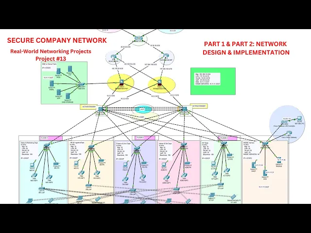
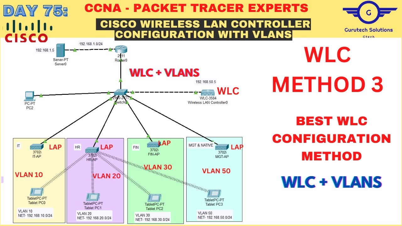

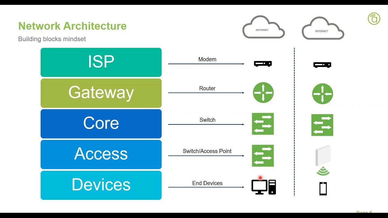
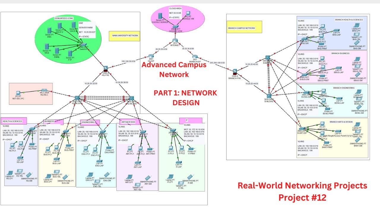






![Computer Networking Course - Network Engineering [CompTIA Network+ Exam Prep]](https://img.youtube.com/vi/qiQR5rTSshw/maxresdefault.jpg)