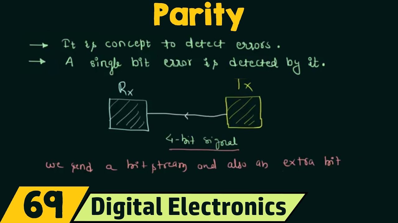
Hey friends, welcome to the YouTube channel ALL ABOUT ELECTRONICS. So, in this video, we will learn about the error detecting code, and particularly, we will learn about the parity bit and the parity checking for the error detection. So, when the data is transmitted between the two digital devices then due to the external noise or the interference, sometimes a few bits get corrupted in the data.
And because of that, at the receiver side, the one is received as zero and the zero is received as one. So, for example, the transmitter is sending 1010 or 10 in decimal, but at the receiver, if there is an error in one bit, then it might be received as 1000. Or in decimal, it will be received as 8.
So, because of this error in 1 bit, the entire data get changed. So, to detect such errors many times, some additional bits are also sent along with the data bits. And with the help of the additional bits, it is possible to detect the error in the received data.
So, the value of these additional bits depends on these data bits as well as the type of the error-detecting code, which is used during the transmission. So, with the help of these error detecting codes, it is possible to detect the error in the received data. So, there are many different methods for this error detection.
But the simplest one is to add the parity bit along with the data. So, there are two types of parity. That is odd parity and the even parity.
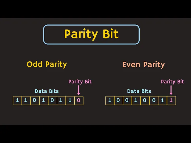
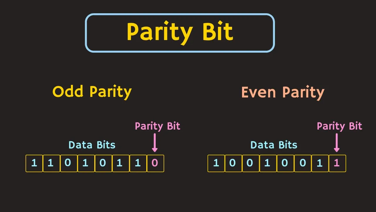
So, in case of this odd parity, including the parity bit, the total number of 1s in the code should be equal to odd. For example, let's say, there are 7 data bits and 1 parity bit. So, in case of the odd parity, the parity bit should be such that, the total number of 1s in the code should be equal to odd.
So, here as you can see, the total number of 1s in these data bits is equal to 4. That means this parity bit should be equal to 1, so that, the total number of 1s in this code remains odd. So, let's take another example.
So, in this case, a total number of 1s in these data bits is equal to 5. Therefore, this parity bit should be equal to 0, so that, the total number of 1s in the code remains odd. Similarly, in case of the even parity, the total number of 1s in the code should be equal to even.
For example, in this code, there is 5 number of 1s in these data bits. That means this parity bit should be equal to 1, so that, the total number of 1s in this code remains even. so, let's take another example.
So, in this case, as you can see, the total number of 1s in this data bits is equal to 4. That means this parity bit should be equal to 0, so that, the total number of 1s in the code remains even. On the other end, if we use the odd parity, then for the same data bits, this parity bit should be equal to 1.
So, that the total number of 1s in the code remains odd. So, in this way, for the error detection, the parity bit is appended along with the data bits, and the entire code will be sent from the transmitter side to the receiver side. So, now let's see, with the help of this parity bit how we can detect the error.
And for a time being, let's consider this odd parity. So, let's say, these are the data bits, and for the odd parity, this parity bit should be equal to 1. Now, when this code is transmitted to the receiver side, then let's say, because of the error, this 1 becomes 0.
So, now at the receiver, the parity checker circuit will check the parity of the received code. So, if there is no error, then the parity should be equal to odd right ! !
But here, because of the error, the total number of 1s in the received code will be even. Because, if you see over here, then the total number of 1s in the code is equal to 4. And since the total number of 1s in the received code is even so the parity checking circuit will detect the error.
Similarly, let's see the case of the even parity. So, let's say, these are the data bits, and for the even parity, this parity bit should be equal to zero. Now, when this code is transmitted from the transmitter to the receiver side, then let's say because of some error, this bit changes to 1.
So, now at the receiver, the parity checker circuit will check the parity of the received code. So, as you can see, here the total number of 1s in the received code is equal to 5. And since it is odd, that means there is some error in the received code.
So, in this way, with the help of the parity bit, we can detect the error in the received code. But we can not find the exact location of the error. Moreover, if there is more than 1 error in the received code, or to be precise if there is an even number of errors in code, then with the help of this parity bit, we can not detect the error.
So, let's say, there are two errors in the received code. So, once the code is received then the parity checker circuit at the receiver side will check the parity of the received code. So, in this case, the total number of 1s in the code is equal to 6.
And since it is even for this even parity, so the parity checker circuit will not generate any error. And it will consider this received code as a valid code. But actually, it is an invalid code.
Similarly, if there is 4 number of errors in the received code then after the parity check, the total number of 1s in the received code is equal to 4. And since it is even for the even parity, so the parity checker circuit once again will not generate any error. And it will consider this code as a valid code.
But actually, this is invalid code. So, as you can see, whenever there is an even number of errors in the received code, then with the help of parity, it can not be detected. But if there is an odd number of errors in the received code, then using the parity bit it is at least possible to detect that error.
So, let's say, for some transmitted code, there are three errors in the received code. So, after the parity check, the total number of 1s in the received code is equal to 5. And since it is an odd number, so the parity checker circuit will generate the error, which indicates that there is some error in the received code.
That means the parity bit can only detect the odd number of errors in the received code. Now, so far in our discussion, we took the example of even parity. But the same is also true for the odd parity.
So, in case of the odd parity also, if there is an even number of errors in the received code, then it will not get detected. So, let's say, this code is transmitted to the receiver side. But at the receiver, there are two errors in the received code.
So after the parity check, the total number of 1s in the received code is equal to 7. And since it is odd, so for the odd parity, this parity checker circuit will not generate any error. And it will consider this code as a valid code.
But actually, it is invalid code. That means we can't detect the even number of errors with this parity bit. But if there are 3 errors in the received code, then the total number of 1s in the received code is equal to 4.
And since it is even, so, for this odd parity, the parity checker circuit will generate the error. So, in short, the parity can only detect the odd number of errors in the received code. So, once the error is detected then the receiver sends the acknoledgedment to the transmitter about the error, and it asks for the retransmission of the same data.
So, in this way, with the help of the parity bit, it is possible to detect the errors. But as I said, we can't find the exact location of the error. Or in other words, it is not possible to correct the error.
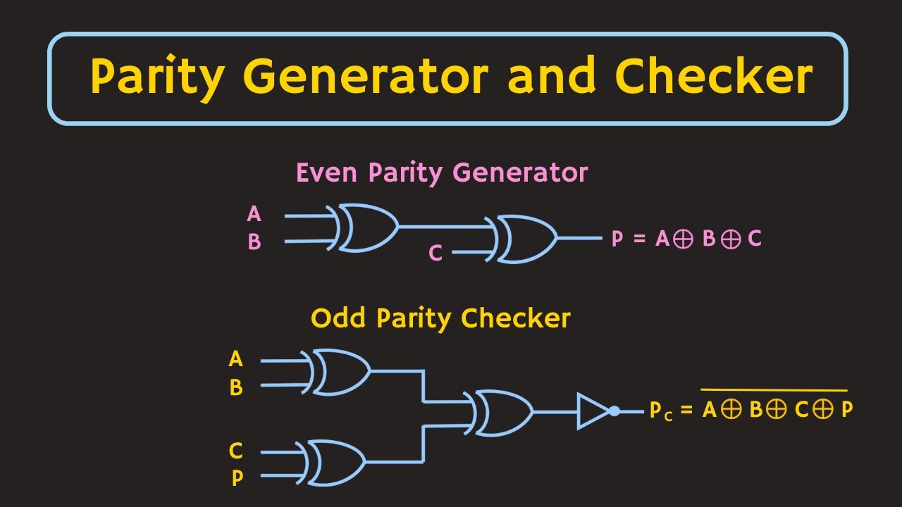
But there are some codes, using which it is also possible to even correct the errors. So, in the next video, we will learn about one of such error-correcting codes, and in the upcoming videos, we will also see the circuit of the parity generator as well as the parity checker. But I hope, in this video you understood about the parity bit, and using this parity bit, how it is possible to detect the error.
So, if you have any questions or suggestions, then do let me know here in the comments section below. If you like this video, hit the like button and subscribe to the channel for more such videos.