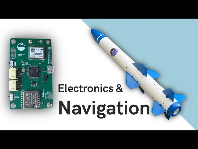
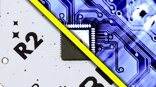
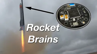
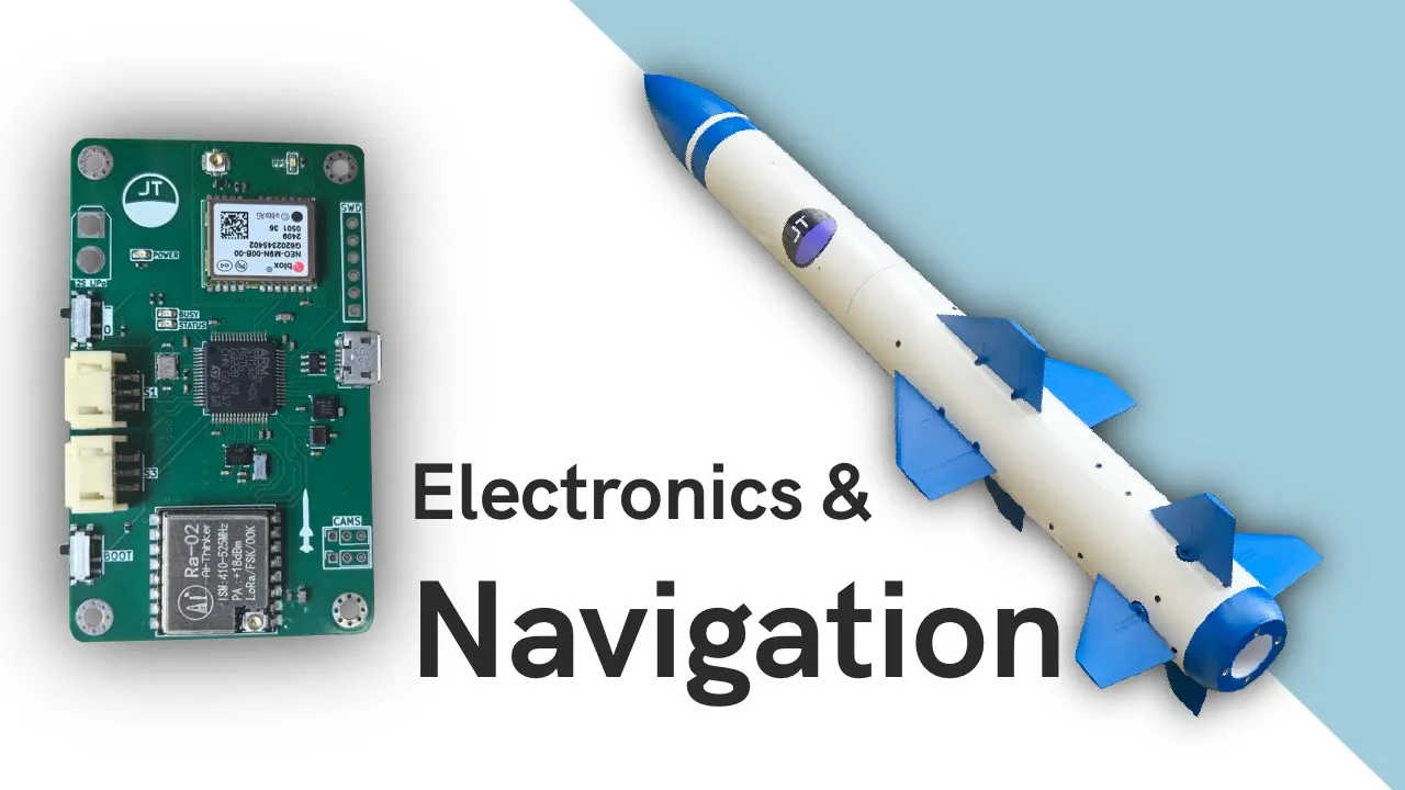
for the past few months I've been working on a model rocket designed to steer itself through the air using a set of control Fs in the last video I went over how I designed the vehicle and today I'll be going into detail on the electronics code and the navigation system to control a rocket like this I need a flight computer that can accurately estimate orientation and position and then use these estimates for stabilization and control I decided to design my own printed circuit board centered around the stm32 f45 microcontroller I've used this chip before and
there are plenty of timers and communication interfaces which are needed to talk to the other chips on this board this includes a magnetometer which is essentially a digital compass and a barometer which is used for estimating altitude this large package at the top is a GPS receiver with the UFL connector for an active antenna there's also a lower radio module placed at the bottom of the board this radio operates at 433 MHz and is a much longer range than the nrf24 I used on my previous rocket however this comes at the cost of a lower
bandwidth so I'm limiting the radio functionality to simple commands and responses as opposed to a continuous stream of telemetry flight data is all recorded locally on this flash memory IC this smaller chip below the MCU is an inertial measurement unit a small package that contains gyroscopes which measure angular velocity and accelerometers which measure linear acceleration this is perhaps the most important sensor on the board so I spent a while looking for a suitable one I settled on the ICM 426 88p from TDK and vense after a few things in the product description caught my eye
firstly the data resolution most affordable mems devices are limited to 16 bits per axis which means that for example angular rates can only be measured in multiples of 0.061 De per second this chip however can somehow provide 19 bits of Gyro data resulting in eight times the resolution my thinking was that this would be very useful for estimating orientation since the numerical integration of angular rates would be more precise the second exciting feature was the support for an external clock this again relates to the Precision of the numerical integration as a more accurate time interval
between measurements should boost orientation accuracy so the board itself is a four- layer design with inner ground and 3.3 volt planes it's powered by a 2s lipo with the help of a linear regulator to get my design built I used pcbway the sponsor of this video PCB way offers printed circuit board prototyping Services which are ideal for getting electronic designs professionally manufactured in small quantities I typically use their standard PCB option along with the turnkey assembly service which is where you provide a bill of materials and they'll Source all of the parts and assemble them
onto your boards for you they also offer high-end 3D printing and CNC Machining which I might be making use of later in this project if you want to make a flight computer like this or a few of some other designs you want to get manufactured visit pcb.com or click the link in the video description okay now we've covered the board itself let's move on to the code everything is written in C in the stm32 cube IDE I'm going to skip over all of the drivers and low-level firmware I wrote and instead I'm going to focus
on the navigation system as it's definitely the most interesting part and I'm always getting questions about it so the role of the navigation system is to fuse data from all the sensors on the board to produce estimates for orientation and position firstly let's go over the orientation filter a querian which is a weird 4D complex number is used to represent orientation querian are useful because they avoid issues like gimal loock are more computationally efficient than rotation matrices and allow smooth interpolation between rotations so that's how the orientation is stored but how's it actually estimated I
configure the IMU to take measurements about 8,000 times per second and write all the data into its internal fifo buffer then in my microcontroller 200 HZ update loop I transfer all the data which is usually about 40 to 50 packets for each packet transferred I call this procedure to adjust the curnan to reflect the small change in orientation that occurred in the 125 microsc since the last measurement this alone can provide an accurate orientation estimate over short time spans but suffers from drift due to small biases in the gyro data accumulating in the estimate another
issue is that the orientation Quan will only be with respect to its initial State and it won't be aligned to any particular reference frame this will be a problem when implementing the position filter to overcome these issues the accelerometer and magnetometer data are fused in this estimate this is done by first using the accelerometer data and simple trigonometry to calculate the Tilt this is represented by Oiler angles and describes which way is down while not being subject to drift over time this tilt is then used to align the magnetometer data so the heading can be
calculated then the Tilt and heading oil angles can be converted to a and a simple slurp can be done to produce a weighted average of the orientation guian and the Tilt heading guian the average is heavily weighted towards the gyroscopes so convergence can take a few seconds from when the computer is booted I found this approach to be very effective but it's worth noting that you will get best results with a calibrated magnetometer accelerometer and Gyros now that these additional sensors are Incorporated the Quan represents the orientation with respect to East North up and it
won't drift over time so this approach works great but there still is a problem when the system under goes acceleration the Tilt angles provided by the accelerometers will be incorrect I therefore only use the fusion approach when on the pan and not undergoing acceleration and once in the air the accelerometer and magnetometer readings are simply ignored so that's how I estimate orientation now onto position I'm using a Caron filter to combine acceleration readings with GPS and barometric altitude a Caron filter is an algorithm that predicts and estimates system States based on a model of the
system and observations so my Caron filter states are 3D position and velocity which is packaged into this six element Vector the carbon filter uses matrices in all of its computations so keeping the state Vector as small as possible was a priority as a result there is no state for acceleration and the accelerometer readings are actually fed into the filter during the predict step there are two update sub routines one for GPS and one for the barometer to actually fuse the GPS parametric altitude and acceleration data the reference frames need to be aligned to get the
acceleration readings in the east north up reference frame the raw data aligned with the body axis can simply be transformed by the orientation Quan this is another reason why having an accurate orientation estimate is so important small errors can misalign the reference frames which can harm the position estimate I then just implemented all of the maths in code which is made a lot easier by this Matrix handling Library I found I used the cmis DSP Library which is specifically optimized and written for arm cortex processes like mine once I'd fixed the bugs I went outside
to get GPS reception and began tuning the filter this can be quite a tricky process but I eventually got some decent results it's worth noting that this drift you see in the position estimate is basically unavoidable and is due to the noise and random walk in the GPS position you could fix this by incorporating GPS correction data from rtk or a differential setup or by increasing the GPS variance in the filter to trust it less but this will only work if your acceleration reading is highly calibrated anyway it works well enough for me how it
is I also want to point out that a Caron filter is not entirely necessary for estimating position and you can get quite good results from a more simple complimentary filter here's one I wrote as an experiment acceleration is used to extrapolate the estimate as before and the GPS and barometer data is used to stop the position from drifting using a weighted average since the velocity will also accumulate errors I hack together some code that uses the difference between the current and previous GPS barometer readings to correct errors in the velocity now I haven't tested this
approach in flight so I'm not too sure how it would perform in a dynamic environment but it is so computationally lightweight that I'm going to run it in parallel with the Caron filter in future flight tests and see how they perform so that's about it for this video it was quite a technical one but I hope you found it useful my next video coming up shortly will be about the Launchpad for this rocket is a pretty crazy design so make sure you subscribe so you don't miss it thanks again to PCB way and thank you
to my patreon members for your continued support finally thank you for watching and I'll see you in the next video