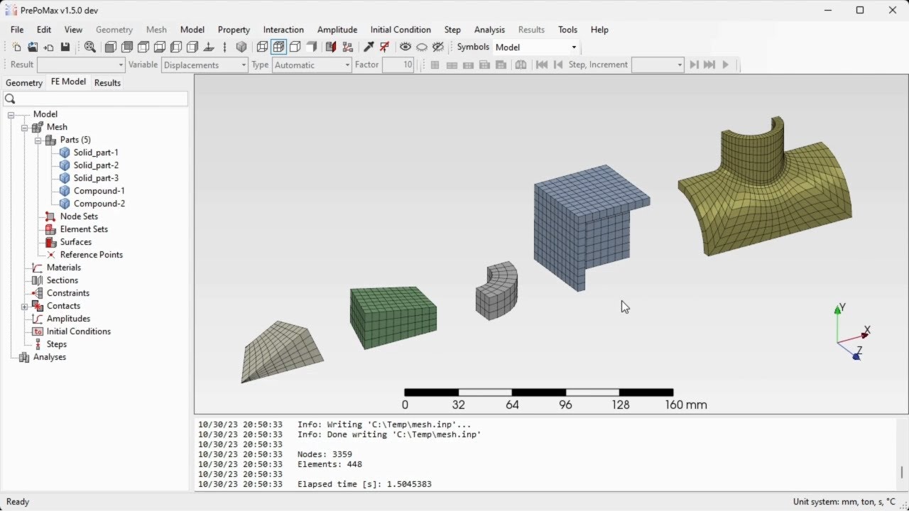
hello and welcome to my next tutorial about prepo mix this time i will show you how to analyze a thin world cup cylindrical pressure vessel mesh with shell elements i will create a new model first select the unit system and now i have to import the geometry i will use the step file format again here you can notice that they model only the mid surface of the pressure vessel and that's because of the way we define shell elements what's more the model represents only one eighth of the whole structure and that's due to the use
of symmetry i will show you how this model was prepared in freecad i will also open the sketch so you can recreate this geometry if you want here all the necessary dimensions and the sketch was revolved using 90 degrees let's go back to people max and now i will create a mesh i have to specify mesh parameters i will use 10 millimeters for maximum element size and i will choose quad dominated mesh because we can use quadrilateral elements for shells let's confirm this and generate the mesh the mesh is already generated so i can proceed
to the analysis setup let's start from material definition uh i will define steel material and i'll provide young's modulus and poisson's ratio using the values that we know from the previous tutorials those are the typical values and let's create a section now and what's different is that in previous tutorials we used only solid section well in this case we have to use shell section because we mesh this with shell elements and i in addition to the material specification i have to provide thickness and this will be 20 millimeters for this particular pressure vessel i don't
have to use offset so i just specify the thickness here and i have to select those two regions because they are separated for the definition of this section let's confirm this and now i can create a new analysis step and this will be static step with default settings we want to use any form of nunarti so this will be turned off and the rest will be set to default let's confirm this and define boundary conditions and loads when it comes to boundary conditions as i said we utilize symmetry so we have to apply symmetry boundary
conditions there are no predefined bc's like that so i have to define them manually using uh displacement rotation boundary condition with the constraint uh on proper degrees of freedom let's start from the symmetry in x direction i will call this sim x and let's pick this edge here and this one here for this constraint and i will constrain the translation in x direction as well as those two rotations here and now i can confirm this and create a new boundary condition of the same type this will be called same y and for symmetry in y
direction i will pick this edge right here and i have to constrain the translation in y direction as well as those two rotations uh right here and now instead of confirming this and going back to the model 3 i can just click ok new and this will let me create a new boundary condition without leaving this window let's define the last boundary condition this will be sim z and it will be applied to those two edges right here this one and this one and i will constrain the translation in this direction as well as those
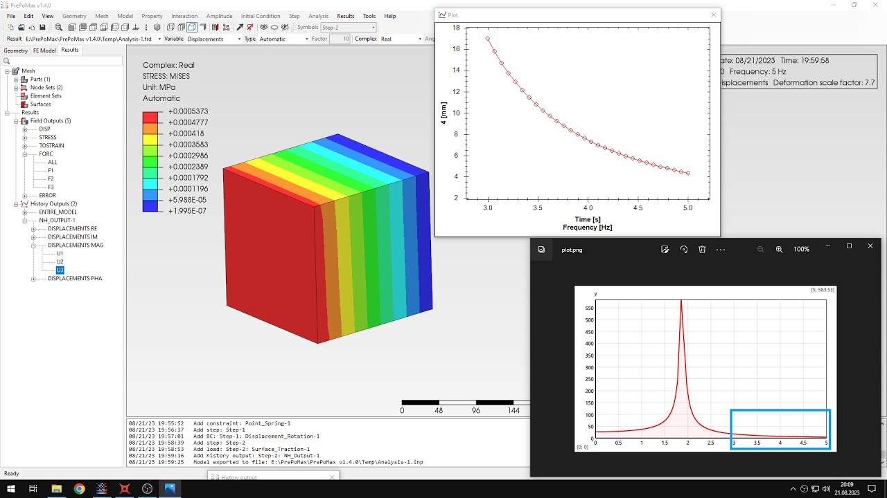
two rotations right here and because i should have mentioned that before the shell elements unlike solids have rotational degrees of freedom let's confirm this and now i can proceed to the load definition i will define pressure load and when it comes to the value here you can see and that we use five mega pascals here are the analytical results we'll go back to this later so let's define pressure five mega pascals acting on those two phases this will be internal pressure and now you can see and the whole model is prepared for the analysis and
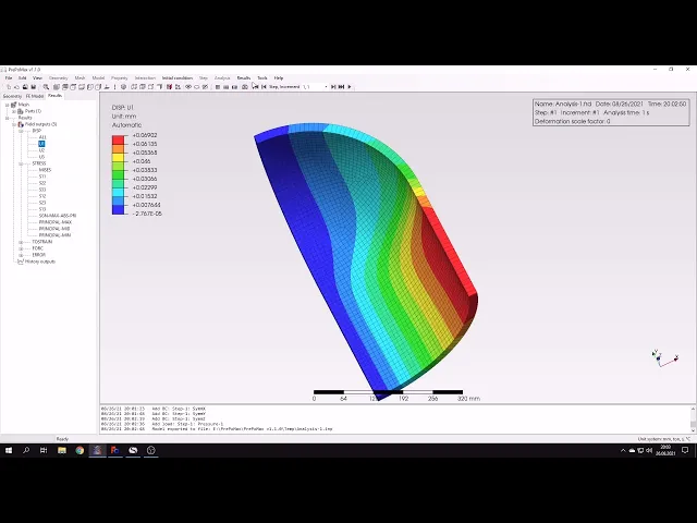
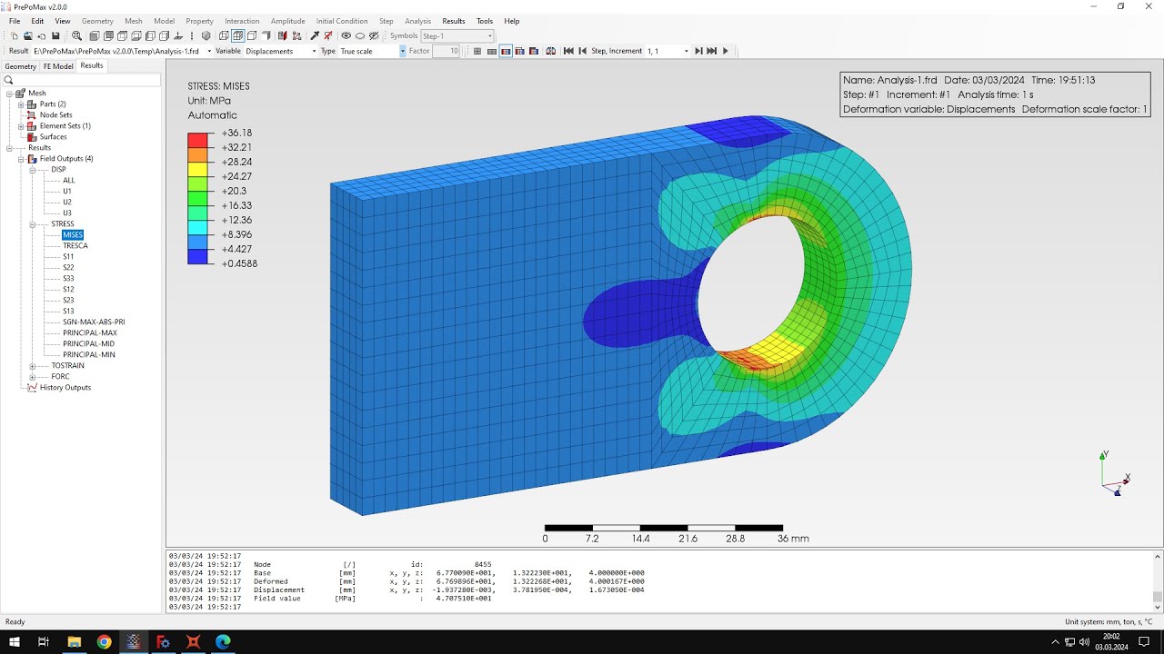
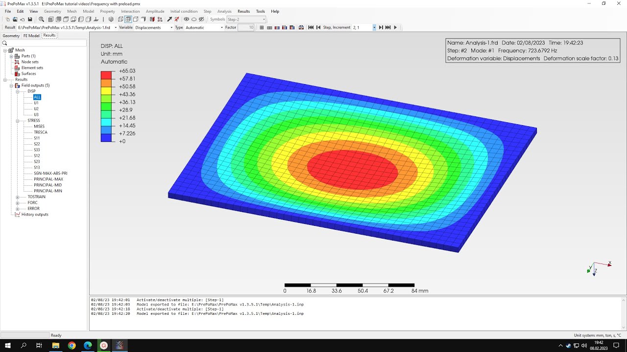
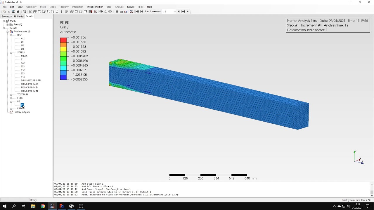
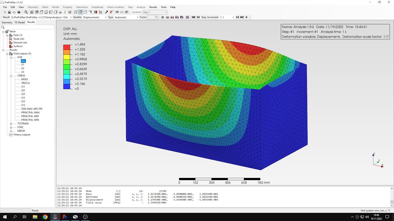
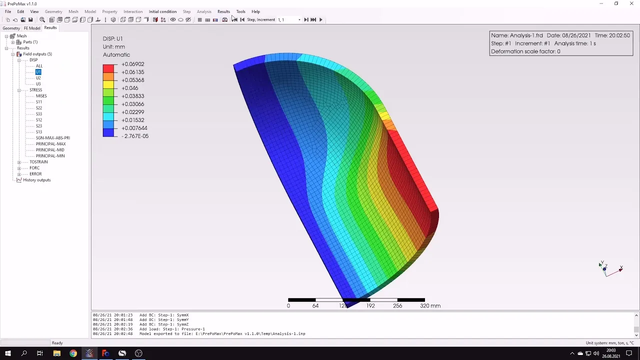
now i can submit this analysis um thanks to the use of shell elements and symmetry it shouldn't take too long to get the results in fact they should be available soon yes they are already available let's open them and here you can see the distribution of displacements and stresses you may also notice that shell elements were automatically expanded solids and this happens for both calculation visualization in calculus i can turn the deformation on because it's currently off i can use the default automatic setting and but but for now let's let's switch the let's switch this
back off here you can see the stress distribution let's compare this with analytical value here's the analytical value of fundamental stress in this pressure vessel and i will use the query tool and to check the stresses in various locations of this pressure vessel and let's check this also here here in in various places this is used to query um selected nodes we use this tool before in in previous tutorials and you can see that the agreement with analytical results is quite good but let's also take a look at displacement in the x direction i can
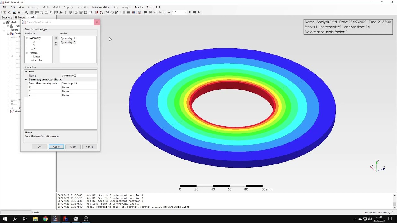
also query this using this tool let's check this here for several locations and i can compare this with analytical value it's since we confirmed the correctness of the results i just want to show you one more thing you can use the results transformation option and apply symmetry in all the available axis and this will make the results look like we have calculated a whole pressure vessel not just a piece of it and while in fact we are dynasty was performed using one eighth of the whole structure but for the visualization purpose we can apply transformation
to and to achieve certain effects that's it for for this purple max tutorial thank you very much for your attention as always feel free to answer any questions that suggest topics for future tutorials in the comments have a nice day and see you in the next video