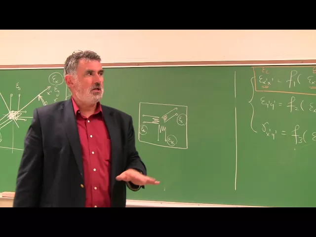
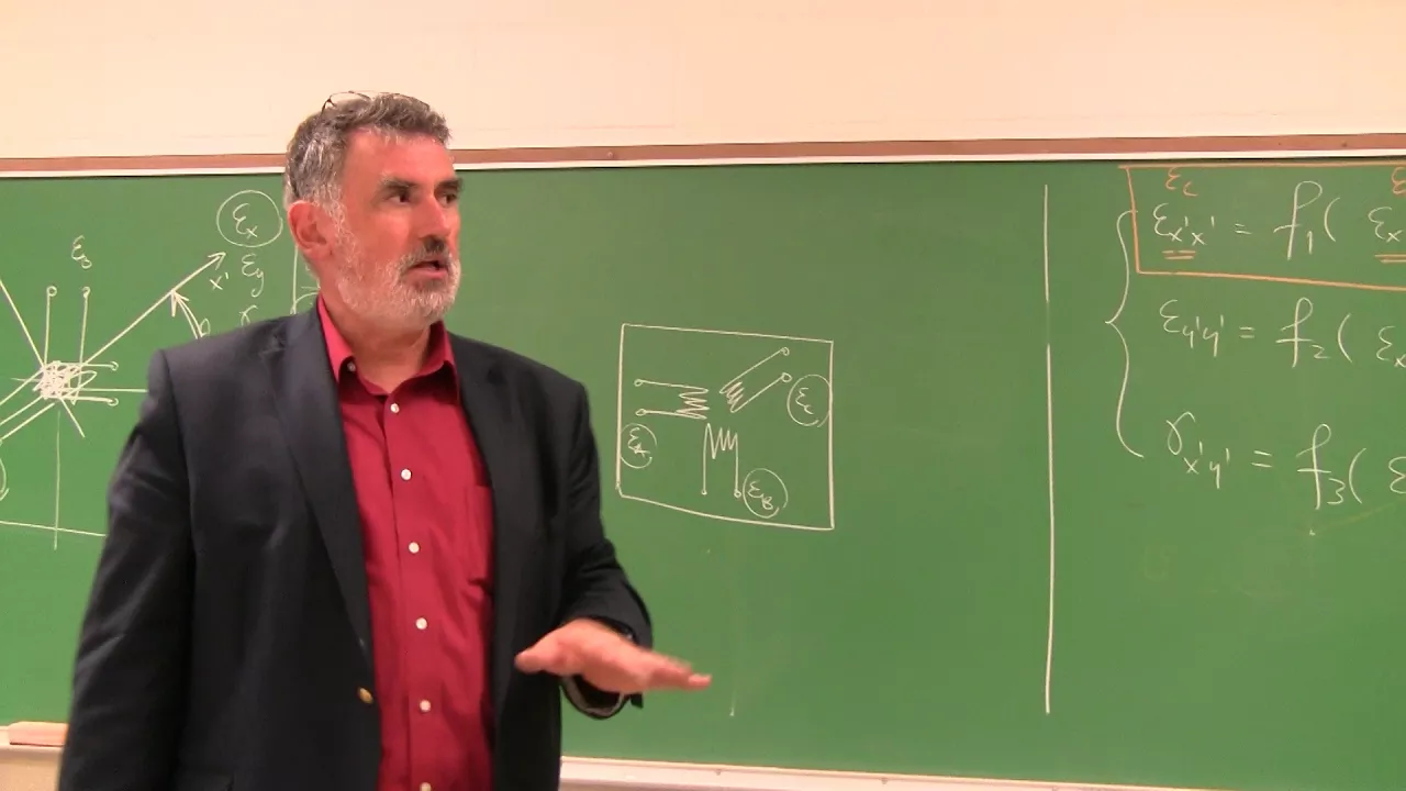
represent the same state of strength and you remember that the 23:12 you have established a number of relationships between these two components of strength and particularly there are a function of the each of the strains can be expressed as a function of the other strains and the annual feedback particularly is a function of two females so I'm gonna say the following I'm gonna provide you with the details I'm sending you to the text book I'm sending you to the chapter upon strain transformation in the text book where you can pick up all these relationships and
refresh your memory on strength transformation but epsilon X prime X prime these come can be expressed as a function of epsilon xx epsilon YY gamma XY and the angle P epsilon Y prime Y prime is another function of epsilon xx epsilon YY gamma XY and feedback and finally gamma X prime Y prime is equal to a function f 3 of epsilon xx epsilon YY gamma XY and people and you can write these relationships backwards as well in other words you can express epsilon xx epsilon YY and gamma XY as the function of X 1 X
X Prime and so on so that being the case that being the case what can you do here I'll let you think for a second about how this can be useful to our task at hand well let's go back to the picture here see we have the anvil Etha here that defines the orientation of this strain gauge the third strain gauge so if we consider this DX prime as an axis and we consider perpendicular to it the direction Y prime as an axis then what you discover here is that epsilon C represents nothing else but
epsilon X prime exponent in other words the normal strength that that's third strain gauge placed at an angle that's trained that width is measured epsilon C represents nothing else but the normal strain in the transforming the rotated coordinate system epsilon X prime X bar so what's left is now here's what to do let's go back to this first equation and look at the following epsilon xx is something that we know this is epsilon a epsilon YY is also something that we know we have measured this is epsilon T this angle theta we know it's and
then epsilon X prime X prime is epsilon C so this by itself now it represents one equation that can be solved for the unknown gamma XY that's how you think and that's where you obtained the measurement of your shear strain in at Point P so you perform the measurement with the first strain gauge you get Absalon XS you perform the measurement to the second strain gauge you get epsilon YY you perform the measurement with the third strain gauge and you get epsilon X prime X prime you know theta the orientation of the third gauge you
use this equation which comes from strain transformation and you can solve it for gamma XY and that's where you get your shear strength and by suddenly you have measured all three strains in the plane XY and the given point now you will need to go back to your textbook for 2312 and you will need to actually dig in find those relationships again they're not going to be a function of theta in fact they're going to be expressed with a function that's 2 theta and figure out how to solve and how to go from epsilon a
epsilon being an epsilon C which are the three strain gauge indications that you are going to be measuring to epsilon X epsilon Y gamma XY this is not something that you're going to do by hand this is something that you need to program in Excel then you're going to use an Excel spreadsheet to process your data to process your measurement of strain from each of the three strain gauges at the given location all right now as a practical matter what I have represented here is a situation where I am the putting at the same location
three strain gauges on top of each other that's a bad idea because the first rain gauge is connected to the materials glue to the material and shares the strain of the material the second one is glued to the first rain gauge and effective measures the strain on top of the first strain gauge and the second strain gauge the third strain gauge would be located on top of everything so all together that's not the bad and in fact the solution ends up having the follow having a particular backing paper on which you have one strain gauge
installed that's not one strain gauge installed as such and the third strain gauge installed as such so this would be epsilon a epsilon this is strain gauge a B and C all these three strain gauges are created on the same packing tape the same technology that allows you to create one strain gauge on a backing plate of a piece of packing material allows you to create three strain gauges this is called a strain gauge rosette so a strain gauge rosette is an assembly of three strain gauges created on the same packing tape at the same
time and the benefit is that from the placement the angles between the string three strain gauges are precisely controlled in other words the value of P by P R the value of theta here is controlled very very precisely by manufacturing all three strain gauges at the same time on the same backing plate as opposed to the case where you would glue one strain gauge glue another strain gauge into a third one in that case you could have small imperfections in measuring the angles and small imperfections in angle theta and as a consequence you would have
some errors that propagate in your measurement of angle so the benefit of having rosettes as opposed to individual strain gauges is first of all that all strain gauges have very closely controlled characteristics similar characteristics because they're all subject to the same manufacturing process second the angle theta is very precisely controlled now strain gauge rosettes come in a number of configurations depending upon how strain gauges are created in this case we would have 0 90 45 degrees but you can have any number there Quentin there is a quite quite the run wide range of configurations of
strain gauge rosettes for different purposes of measuring strength now we are going to be using the strain gauge rosette we're going to be using several strain gauge rosettes for which we're going to be measuring strain in the first the second and the third strain gauges to be able to fully determine the state of strain at the given location on the surface of a specific obviously you remember that any at any point excuse me in a material there are nine components of strain six which are defined because train is a symmetric tensor second-order tensor however we
cannot measure there is no technology to allow you to measure strength inside a piece of material we can only measure surface strength so in our experiments we are limited to measuring surface strains and specifically if you choose at the point on the surface of a part the reference system x and y you're going to be able to measure Sigma xx sorry epsilon xx epsilon YY and gamma XY now I'm assuming that the reference plane for that surface is X oh why it could very well be XO is that Y or Z and so on or
could it be just an arbitrary surface at any point on the surface of a part you measure the strains corresponding to that particular part that particular location in the plane corresponding to the face the plane of the face so those are the components that get measured so I think this now clarifies the second step which is how do you use strain gauges which are fundamentally normal strain measuring transducers to actually perform a full strain measurement at the point which includes the measurement of shear strain and you said that's an indirect measurement but it can be
accomplished quite easily as the scribe we're gonna stop here and they're gonna continue with the third part of these lock in a minute