(Music) Hi radioelectronics guys! In this video we are going to show you how modify a commercial FM radio receiver, whose working band covers originally 88 to 108 megahertz, in order to receive broadcasts from radius between 118 and 150 megahertz. This includes the air band, which is normally located between 118 and 136 megahertz, in which we will have the opportunity to hear the control tower of a nearby airport and to the aircraft that use it.
We can also hear the band radio amateurs which in Europe is between 144 and 146 megahertz and in America from 144 to 148 megahertz and of course all services included in the range of 136 to 150 megahertz. But before and to know exactly what we are going to do it is convenient to talk a little about the different types of receivers and the methods they use to get process high frequency signals. In addition to how to modify the receivers, and if you stay to watch this video until the end, you will learn many interesting things about radio and about electronics in general, With special emphasis on performance of the king of receivers; the superheterodyne.
(Music) To assimilate what I am going to explain, it is convenient at least that you have an idea of how a radio signal is formed, know what amplitude modulation means or frequency modulation and have basic knowledge about most elementary electronic components, like capacitors and coils. (Music) We started! The simplest receiver there is it is the so-called radio galena, also known as a crystal receiver.
I imagine that the vast majority of you you will have built one of these sometime. If you have not done it yet, I recommend that you put hands to work. It is a very rewarding experience.
A typical scheme of this apparatus is the one you can see in the image. Its operation is very simple and starting from it we will develop the exposition of the rest of the versions. But let's see this same scheme from a standpoint that will allow us to better understand its operation and also that of those who come later.
Let's take a look at the schematic blocks of an elemental receiver. As you can see, the antenna picks up the radio signals from different stations. In principle these signals are very weak and to reinforce them a little and to be able to handle them better, they first go through an amplifier that increases their respective amplitudes.
Once amplified the radio signals are applied to a circuit that selects only one of them; the one we are most interested in hearing at that time. This circuit is what we know as "tuner" or "frequency selector". When we have already selected the signal then it's time to "demodulate" it, that is, throw away the radio frequency that we can't hear and stay only with the low wave frequency that if we can listen.
The circuit in charge of doing this it is the so-called "detector" or "demodulator". (Music) At the exit of the detector we already have the sound, that we can hear by applying it to headphones. If we want to use a speaker, then it will be necessary make pass to demodulated signal first by an audio amplifier in order to obtain the necessary power.
Now let's see what these blocks are in the electrical diagram of the crystal receiver, or radio galena, which we present to you before. (Music) Look how the signal is captured by the antenna and is induced in the "resonant circuit" or "tank circuit" thanks to the magnetic coupling between the coils. Note that to get a correct impedance matching, the number of turns of the secondary is greater than those of the primary.
We could assimilate this as a species radio frequency amplifier, the first block we talked about, since the voltage induced in the secondary it will be greater than the one that exists in the primary. Tank circuit tunes and selects only one of the signals received by the antenna, that is, the one we want to hear. Here we have the block we have called "tuner" or "frequency selector".
The signal selected by the circuit tank is applied to a germanium diode in charge of letting only one half pass signal of the chosen station. Remember that a diode it only drives one way. Look how after this, the "audio" or "low frequency" signal "rides" over the middle of the carrier.
(Music) The next condenser does a very special job. We could say that it is in charge of "filling" the empty spaces that exist in the signal, thanks to the load that it stores in the peaks. (Music) In addition, it earthes the remains of radio frequency that may have been sneaked, leaving only the audio signal on its terminals.
The diode, together with the capacitor, they form what we have called "detector" or "demodulator" on the block diagram. Finally, the audio signal obtained is applied to the headset through which we can hear it. Galena radius can be improved with the addition of active components, like transistors for example.
These components can used in different ways; like amplifiers, like mixers, converters, etc . . .
Let's see a simple example of this analyzing the scheme of a radio receiver with superior characteristics to radio galena. Look at the block diagram that we present to you in the image. If we take part of the signal that we have previously tuned and we introduce it again at the entrance of the radio frequency amplifier section, this "feedback" signal will be added to the one that enters through the antenna, with this we will reinforce the amplification and we will obtain at the entrance a signal of greater spaciousness and better features than the original.
The device that works by this technique is known as "reaction receiver" or "regenerative receiver", and for years it was the delight of radio amateur for its great sensitivity, although it suffers from a certain lack of stability and its selectivity is not the best. (Music) In the electrical scheme that we put you as an example of such a receiver you can see how the amplified signal in the collector of transistor "T1" is reintroduced at the entrance, that is, to the base of the transistor, via auxiliary winding "L1", which induces in "L2" part of the signal amplified by the transistor. To get a sensitivity and moderately good selectivity the so-called "tuned radio frequency" receiver was used.
It can be said that this type of receiver was the first that was commercially offered to the general public, although the time it lasted in the market was really very short. It had several selective amplifier steps, usually two, tuned at the frequency you wanted to receive, so three "tank circuits" were needed, which had to resonate at exactly the same frequency at any position on the tuning dial. This was achieved in the entire band of medium waves thanks to the use of so-called variable capacitors "in tandem" of "three modules" or "sections".
By moving the axis of the aforementioned variable capacitor the plates of the three sections are moved at the same time, allowing the three tank circuits modify their frequency in unison. However, the tuned radio frequency receiver, at that time made with thermionic valves, it suffered from several drawbacks. In high frequencies appeared sporadic oscillations that made reception difficult or even canceled altogether, so this system could not be used in short waves with good results, although circuits with designs appeared specials that tried to alleviate the problem.
Also, to keep all three circuits resonant on exactly the same frequency throughout the entire band it was not easy to achieve due to the tolerances in the manufacture of electronic components. This problem increased with the aging of the components, so the receiver lost sensitivity over time. (Music) Finally, the American engineer Edwin Howard Armstrong found the solution.
This man was also the one who had previously invented the "regenerative receiver" and later also the so-called "super-regenerative receiver". The new reception system was called "superheterodyne" and it is the one that is used universally today in the majority of receiving equipment of any kind and of a medium-high quality. Precisely the FM receiver that we will modify to be able to hear VHF broadcasts is of this type, so let's dig a little into its basic operation.
We will try to know what we have to change in its circuitry to achieve our goal with the best possible results. The principle on which this receiver is based is the so-called "frequency mixing". What is this about?
. . .
you ask. Don't worry, I'll explain it to you right now. (Music) The frequencies mixing is a phenomenon that occurs when we add two signals of different frequencies.
For example, suppose we have a 900 kilohertz signal and another of 800 kilohertz. We take both and put them in a "mixer" circuit. So at the exit of this circuit and after a process of "detection" and "filtering" we obtain a signal of 100 kilohertz, that is, the one that results from subtracting the one with a lower frequency from the one with a higher frequency.
Some confuse this process with the modulation of a carrier by means of an audio signal, since in both cases the signal needs to be detected to obtain the final result. However, one thing has nothing to do with the other. Someday we will talk about it.
Also, and this is important, if one of the two signals used in the shake is modulated in amplitude or frequency, the difference signal obtained after it will preserve the amplitude or frequency modulation of the original signal. This is something very advantageous that is taken advantage of in the superheterodyne receiver for transform the signals received by the antenna, in another signal of fixed frequency and lower than the original, preserving the initial audio information. This signal resulting from the mix is known as "Intermediate Frequency" or "IF", and the transformation process is called "frequency conversion".
(Music) The intermediate frequency signal obtained from the mix podemos amplificarla y procesarla con mucha más facilidad y con menos problemaswe can amplify and process it much more easily and with less problems than the high frequency signal received by the antenna. It is clear that in a superheterodyne receiver one of the signals to use to mix is the one we receive from the station. The other necessary signal that we will add to this we will have to produce ourselves by a device called a "local oscillator", included in the receiver circuitry.
We present a block diagram in which you can appreciate what the "frequency converter" of a typical superheterodyne like. Stick with this designation which is important . .
. . .
. "frequency converter". This includes all the steps you see in the image, that is, the RF amplifier, the mixer, the local oscillator and the filter intermediate frequency output.
As you can see, in superheterodyne receivers, it is necessary to use a variable tandem capacitor similar to that used in tuned radio frequency receivers, but only two sections. One of these sections is used in the tank circuit that selects the signal that enters through the antenna. The other section is used in the tuned circuit which produces the signal from the receiver's local oscillator.
Likewise, as was the case with tuned radio frequency receivers, the two resonant circuits to which the aforementioned tandem capacitor belongs, they must have a synchronized movement. However, while the tuned radio frequency receiver all tank circuits had to be set to exactly the same frequency, in the superheterodyne they must have different frequencies. With this we will achieve that between the two frequencies to which tuned circuits resonate, there is always a difference equal to the intermediate frequency of the radio receiver, whatever the position of the variable capacitor sections.
What we are going to achieve is that, with whatever signal we tune in, at the output of the converter filter always we have a signal of fixed frequency and lower frequency than that received by the antenna and equal to the one we have chosen as the intermediate frequency. To better understand this process we are going to graphically see the values that would have the frequencies of each of the mentioned parts of a basic superheterodyne FM receiver. (Music) The value of the intermediate frequency used by these receivers it is 10.
7 megahertz. Look at the coordinate graph in the image. If we represent the axis displacement of the tandem capacitors by a vertical line, we see how the two frequencies stay equally far from each other throughout the tour.
There is always a difference of 10. 7 megahertz between them. That is the frequency that is obtained as a result of mixing the signal of a station with which the oscillator of our receiver has at that moment.
We insist on indicating the name that receives this difference signal. It's called "Intermediate Frequency" or "IF". (Music) Once the intermediate frequency is obtained, it is amplified as necessary without the problems they had the selective "all band" amplifiers of the tuned radio frequency receiver.
A complete block diagram of the superheterodyne receiver is what you can see in the image. It is clear that quality and reliability over time of an amplifier designed for a single frequency, the "IF" of the supereterodyne, it may be much larger than one amplifier may have designed for much higher frequencies and with a coverage that covers an entire band of a width of 20 or 30 megahertz, as occurs using tuned radio frequency. The superheterodyne system is used today in the vast majority of receivers of a certain quality.
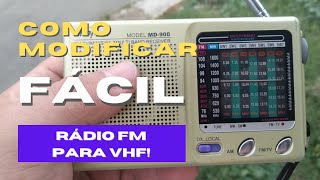
The one that we are going to convert into a VHF receiver it is a model of the Sanyo brand, already discontinued. However you can use another, of any brand, as long as it is of the superheterodyne type with analog tuning in which you have access to the two tuned circuits that it incorporates. Also, for the reasons that I will discuss later, it would be interesting if it had a generous power audio amplifier accompanied by a good speaker.
Before going any further, I want you to be clear about a couple of important points. The first is that only you will be responsible for the damages that may suffer the receiver when handling it. All the actions that you carry out will be done at your own risk.
I will show you two ways to do this modification. Both allow you to have your receiver back in its original conditions just putting things back the way they were. However, one of them is much easier to implement than the other.
The decision to choose one of them is yours alone. Lastly, whatever you do, do it carefully and neatly. A job well done needs calm, leaving the nerves and the rush aside.
(Music) The changes that must necessarily be made to the FM receiver to be able to receive the VHF there are basically two and both must be done in the converter. You will see this more clearly if I show it to you on the block diagram. The first change is to modify the frequency of the local oscillator.
We have to get it to start at 128. 7 megahertz and if possible it will reach 160. 7 megahertz.
We need an IF of 10. 7 megahertz with antenna signals from 118 megahertz onwards. For that reason our local oscillator it must start operating at 128.
7 megahertz, that is, 10. 7 megahertz higher than the lowest frequency we want to receive, that in our case it is, I repeat, 118 megahertz. (Music) The second change is to modify the tuning of the antenna input tank circuit to match the new frequency range to be received, that is, from 118 megahertz onwards.
This means that the antenna signal input instead of starting tuning from 88 megahertz from the change it will do it from 118 megahertz. With a little luck this tank circuit it will be able to tune frequencies up to 150 megahertz. (Music) These are the two modifications that must be made to our receiver and they can be carried out in two different ways.
The first is more professional than the second. However, the second is much easier to perform than the first and also less committed. You choose which of them you want to implement in your receiver.
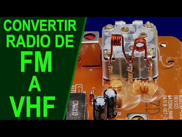
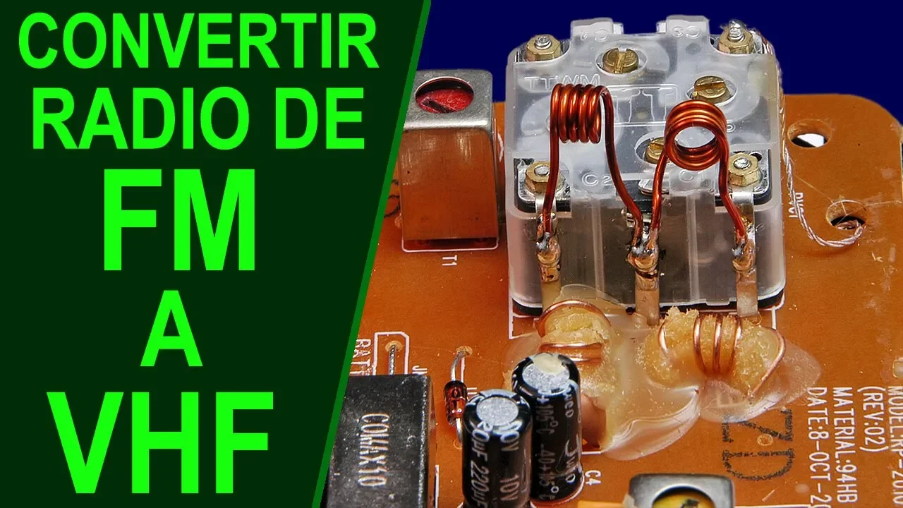
Let's take a look inside the radio equipment that we'll use as a guinea pig. These are the coils that we have to modify to make the change. One of them belongs to the antenna input amplifier step and the other to the local oscillator of the receiver.
The first option is to change them directly by others that make tank circuits resonate on the desired frequencies. Without a doubt, this is the option that has more elegance and more professionalism. However it is also the most risky and most difficult to carry out.
Effectively. To avoid frequency shifts and sporadic oscillations, as they are circuits that handle very high frequencies, manufacturers resort to applying of a binding substance such as wax and wrap the coils with it with the idea of avoiding vibrations that modify the frequency and to provide more stability to the circuit. Therefore, this first way of making the modification can become very cumbersome.
especially in certain receivers in which when assembling the receiver they have been very generous with the wax. I insist; Doing it this way is a decision that only you must make. If you choose it, I recommend that to start you change the coils for others with the half of the turns that the original coils have and from there you start experimenting.
The section of enameled copper wire you use it can be between 0. 6 and 0. 8 millimeters.
(Music) Why do we have to reduce the turns of these coils? The answer is that, in a resonant circuit the higher the inductance of its coil the frequency at which it resonates will be lower. Conversely, the lower your inductance, the higher your resonant frequency.
This is the reason why we must remove some turns from the two coils. The objective is to lower its impedance so that the tank circuits to which they are connected resonate at higher frequencies. This is precisely what we are pursuing.
Once the change is made, the receiver will be adjusted in the way that I will indicate later. (Music) The second option is much easier to perform and also if we want to go back it will be much easier to leave the receiver as it was at the beginning. It is about reducing the inductances of the coils mentioned above placing other additional coils in parallel.
This is something similar to what happens when we connect two resistors in parallel. The new value obtained will always be less than any of the original values. Effectively, if we connect another coil to a coil in parallel, its inductance will be reduced.
The effect will be the same as if we change the original coil for another with fewer turns. This operation is much easier to perform in practice than have to change the original coils, partly for the reasons already discussed and also, because we will not have to disassemble the receiver printed circuit board. To know the location where we would have to weld the new coils just think that the original coils are connected in parallel with their corresponding variable capacitors.
Therefore, if we solder the new coils to the terminals of the mentioned variable capacitors, actually we will be placing them just in parallel with the original coils, and in this way we will have our objective accomplished. (Music) To achieve fine tuning in the higher frequencies, both on the tuning variable capacitor and the local oscillator, have connected in parallel with them small adjustable capacitors called "trimmers", of low capacity. The trimmers are used only during the receiver calibration and tuning process and they are not accessible by the user.
They improve the functioning of the receiver when tuning signals in the upper part of the band and they get a correct sweep of it, keeping the difference between the received signal and that of the local oscillator constant. Due to their low capacity, they have very little effect at low frequencies. when the variable capacitor of its section is closed and the capacity of the latter is maximum and therefore much larger than that of the trimmer itself.
(Music) The inner diameter of the added coils you will have to try it out until you get the best results. A good option will be to start with 5 mm but you can experiment with measurements between approximately 4 and 6 mm. As in the previous case the section of enameled copper wire to use it should be between 0.
6 and 0. 8 mm. Take a good look at the position in which we have mounted the coils.
You must be careful to place them perpendicular to each other so that their magnetic fields influence each other as little as possible and there are no interactions with each other. As we have already hinted, this option has, among others, the advantage of not having to disassemble absolutely anything from our receiver except for the rear cover, or front cover in other cases and therefore we will run a lower risk of causing you harm. If after making the modification you want to leave your receiver as it was at the beginning you will only have to desolder the new coils and the matter is finished.
Whatever system you use, after the modification you will have to adjust your receiver to get it to work properly in the new frequency range in which the receiver will have to work. Before starting we want to emphasize the fact that you should not be discouraged if in a first calibration attempt your equipment does not work as expected The most common is that this happens. But .
. . don't give up!
You have to be aware that to get good results you must dedicate time and experimentation to the subject. Nothing of value is achieved by easy means. Now let's move on to calibrating and adjusting the receiver.
(Music) Undoubtedly the best way to adjust our equipment according to the new features we want it to have it is with the collaboration of a radio frequency generator, which incidentally, not everyone has it. But don't worry because I'll show you a way to do it, more or less acceptably, without the need to have one of these instruments. However, before we begin to explain how to make this adjustment, I want you to be clear that there are technical differences in the processing of radio signals that we want to hear.
For example, in the air band amplitude modulation is used, that is, AM, and not FM. The radio amateurs working between 144 and 146 megahertz or up to 148 in the American continent, they do use frequency modulation in most cases, but with a narrow channeling of 12. 5 kilohertz and maximum deviation of 2.
5 kilohertz, or channelization of 25 kilohertz and maximum deviation of 5 kilohertz. Most services and companies that work between 136 and 150 megahertz they use by official regulations a channeling of 12. 5 kilohertz.
However, each commercial station in the 88-108 megahertz band, which is what the manufacturer has designed our receiver for, consumes a bandwidth of 200 kilohertz with a modulation level of 75 kilohertz. In addition, the demodulator of our equipment is designed to process FM signals, and not AM. All these differences will make the performance of our receiver in the new frequencies it's going to be lower than we'd like.
For this reason we would be interested in doing this experiment with a team that has a good loudspeaker and a audio amplifier of a certain quality and medium power. At least this will help to alleviate the above deficiencies since in most cases the detected audio signals will not have a large amplitude. OK!
. . .
Next we will explain how to make a standard fit. Ideally, do it with a radio frequency generator. However, as we have already mentioned, We will also tell you a way to do it when you don't have it.
(Music) First we have to calibrate the local oscillator of our receiver in order to receive a 118 megahertz signal in the lower part of the tuning scale, which is the beginning of the air band. For this we start up our receiver and we completely close the variable tuning capacitor, what will face the fixed plates with the moving ones. This will make the two tank circuits, the antenna input circuit and the local oscillator circuit, resonate at their lowest frequency.
We proceed to produce a 118 megahertz signal with the radio frequency generator, applying it to the antenna input of the receiver. Later we will tell you how you can do the same when you do not have the radio frequency generator. At this time it is convenient that the radio frequency produced by the generator is of a medium-high level and also that it is frequency modulated with some stable audio signal, so that we can receive it easily, since what interests us at first is to adjust the local oscillator at its correct frequency.
Now we will have to modify the separation between the turns of the oscillator coil until you hear the modulation of the generator signal. If in the end we want to be able to tune frequencies as high as possible it will be convenient to keep the trimmer of the variable capacitor of the local oscillator completely open, that is, adjusted to its lowest capacity. Once this is done, we will reduce the generator's radio frequency output level, making it as weak as we can but in a way that allows us to continue hearing its modulation.
Next, we have to retouch the coil of the antenna input step until the received signal is maximum. The aim is to achieve the highest possible sensitivity of the receiver at low frequencies. At the moment we do not touch the trimmer corresponding to this section of the condenser at all.
These settings will be repeated two or three times until you get the best results in the lower part of the new frequency band. (Music) If you don't have a generator You can use the method that a user of our blog told us called Norberto, from Córdoba (Argentina). Thank you very much, Norberto, for the idea!
. I explain how it is. It is about using another FM receiver different from the modified one tuned at 107.
3 megahertz. At that point on the tuning dial your local oscillator will be producing a signal with the frequency of 118 megahertz that we need. If we now bring the two receivers close enough and place them next to each other, we could possibly use the local oscillator signal from the first receiver as a reference to adjust the one we want to modify.
You get it . . .
right? It is logical that with this method the adjustment will not be as comfortable as doing it with a generator, but as a well-known spanish saying goes . .
. . .
. "The man who has nothing else, with his wife has to go to bed. ".
(Music) After setting the lower part of the new frequency range now touch the setting at the top. Most variable capacitors used in FM receivers have a coefficient of approximately 1. 25 so if we have adjusted the low part to be able to receive the 118 megahertz it is easy that from above we can receive signals of up to 148 megahertz.
Logically, if we want our receiver to go higher still, we will have to sacrifice the lower part a bit. You can't have everything in life, buddy! To adjust the high part of the band we have to fully open the variable capacitor and tune in a signal on the order of 146 to 148 megahertz.
Once we are receiving the aforementioned signal we will adjust the receiver's antenna input trimmer until reaching the maximum level without touching the coil at this point. It is now convenient to return to the lower part of the tuning scale, about 118 megahertz and retouch the input coil for maximum receiver sensitivity at this frequency. It would be wise to run the above steps two or three times to get the best results.
(Music) And with this we conclude the adjustment of the receiver. I hope you liked this video. We will return soon with more interesting information.
Do not stop visiting us. Until then . .
. greetings, friends!