Welcome all of you, we are in week 7 and I see that, many of you working very hard on the assignments and watching videos regularly. So, that is a very good thing and I am quite happy that, there is a lot of momentum and you are able to catch up with many of the assignments that are given a lot of announcements that have been put out last week. So, please go and read the announcements and ensure that, if you have not done registration for the exam, please go ahead and register for the exam.
Also, there have been announcements about the registration process itself and what is going to be in the exam. So, in summary for 50 percent of the final mark that you are going to get after certification, for the 50 percent, we will take best three assignments out of these several assignments that are given. So, even if you are lost out on the first few assignments, you have time to catch up and do the other assignments.
The other thing is with respect to the certification exam, we also announced the policy that many of the questions in the final exam will come from the assignments itself. So, it will not be the exactly the same questions, but the model of the final exam will be very similar to the kind of questions that are there in the assignments. So, in some sense, the assignments are supposed to get you ready for both the field and exposure to the field and as an immediate thing, it is also getting you ready for the exam.
In that sense, it is necessary for you to do as many assignments as you can, so that you are more comfortable, when you take the test. So, in this week, we are going to do something slightly in a very different way. So, what we are going to do is, we are going to take a specific problem, which is written up as an algorithm and we are going to see, how this algorithm can be implemented in hardware.
So, the problem, we are going to take up is, design of what is called the GCD machine. So, GCD stands for Greatest Common Divisor. What we are going to do is, we are going to take the algorithm and write it down step by step, understand what it does and see how we can translate that into hardware and we will also see, how to take that hardware and translate that into Verilog.
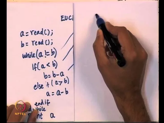
So, we have a quiet of few things at hand, but let us start with the GCD algorithm itself. So, GCD algorithm is attributed, this particular version of GCD algorithm that I am going to use is called Euclid’s algorithm. So, Euclid’s GCD algorithm is roughly like this, so I am going to write it on left side.
So, let us say there are two numbers and I want to find the GCD of that, so I need to go and read the numbers from the user. So, imagine this as a template for, may be a program written in C or C plus plus or it does not matter. So, I am not going to write syntactically correct code, as long as you understand what the meaning of whatever I am writing is, that is enough.
So, Euclid’s algorithm is essentially this, you go and read the numbers and we have a loop, which is running as a while loop. While, a is not equal to b, so if a and b are not the same, so this one works for, if a and b are both positive. So, if a and b are not the same, then Euclid’s algorithm is as follows.
If a is less than b, then subtract a from b, else, so this else will be true, only if a is actually greater than b. So, we have started with the check, while a is not equal to b. So, we already know that, if I have to execute this if condition, then a should not be equal to b So, what are the three possibilities, given two numbers a can be equal to b, a can be less than b or a can be greater than b.
So, while a is not equal to b, which means either a is less than b or a is greater than b So, if a is less than b, subtract a from b, otherwise subtract b from a and so this is end of the if statement and this is end of the while loop. At the end, this while loop will stop or it will terminate, only when a equals to b and at that point, a is actually a or b, either one is actually the GCD. So, this is the crux of Euclid’s algorithm.
So, let me go over it again, you read the two numbers and if a and b are already the same, they are already the greatest common divisors of each other. So, if I give you number like, what is the GCD of 10 and 10, so 10 is the GCD of 10 and 10 So, then if a is equal to b; that is the GCD itself. Otherwise, you keep running a loop till a becomes b and the transformation that we do is, if a is less than b, subtract a from b, else we know that a is actually greater than b, in that case subtract b from a.
So, let we do a few examples, so I will take one small example first. So, let us say I want to find out the GCD of 42 and let us say 16, I want to find the GCD of 42 and 16. So, a is initially 42 and b is initially 16, so I want to find that the GCD of this.
So, since a is greater than b, so a is not equal to b, so the while loop is, this condition is true, so is a less than b, no; a is actually greater than b. So, what I am going to do is, I am going to take 42, subtract 16 from it and put it again in a, this is for a and this is for b. So, 42 minus 16 is 26, now I have 26 comma 16.
So, I run through this condition once more, a still not equal to b, so I do 26 minus 16, so that is 10. So, now, a becomes 10 and b becomes 16, at this point b is greater than a, so we need to subtract a from b, so I subtracted. So, this is 10 and 16 minus 10 is 6, then I have 10 and 6, so 10 is greater than 6, so I subtract 1 from the other, then I have 4 comma 6, then 4 and 6, 6 is greater than 4, so I will subtract 4 from 6.
So, I have 2 comma 4 and 4 and 2, I will subtract. Now, at this point a is equal to b, so GCD of 42 and 16 is 2. So, this is easy, because 42 is 40 plus 2, so it is an even number and it is actually in turn, in this case happens to be the smallest even number 2.
So, let me take another example, let us say, I want to find out that the GCD of 60 and 45, so a is 60 and b is 45, let us say. So, again let us do this, so 60 minus 45 is 15 and on the other side, you have 45 itself, then 45 is greater than 15, so I subtract that, so I get 15 and 30. So, now, 15 and 30 again 30 is greater than 15, so now, it is 15, at this point both a and b are equal and we have GCD is 15.
So, this is what I want to do, so I want to repeatedly subtract, so that I get to this GCD, at this point, I can stop and print a. So, this is the overall crux of the algorithm and let us see, how to translate this in terms of hardware. So, what I am going to do is, I am going to show the algorithm and to think in terms of hardware, we need to do a few things.
So, let us start with this particular set up, so I am going to leave the algorithm as it was before. So, this is the algorithm that, I had and let us see, how to do all of these things. So, if you want to think in terms of hardware, there is a equal to read and b equal to read, some where we need to get inputs from the user, so let us not worry about that.
The first thing I want to think about is, how to take this algorithm and there is, there seems to be a loop that is running and I need some control of the loop. But, I also have various things that I have to do here. So, let us see, what are the different things that I need to do, so there is some reading from the user, that I am going to ignore for now.
So, if a and b are put in registers, somewhere if I have control over a and b putting in the registers, I will use them. Now, look at these things, if a is not equal to b. So, this seems to indicate that, I need to be able to compare a and b.
So, a compare with b, I need some hardware, which will do that, because I want to compare a and b. So, if I want to compare a and b, I can look at each and every bit position and see if the bit positions are equal or I can do it in several ways. So, I need to compare, then if a is less than b, again this is actually comparison.
So, this is not just bitwise comparison, we need to do arithmetic comparison. So, it looks like, we need another comparison. So, we need a comparator, a comparator is a piece of hardware, it is a circuit which can take two numbers a and b and compare a and b and tell us, whether a is less than b, a is equal to b or a is greater than b.
So, if a is less than b, there seems to be need for comparator. So, the else is also going come from the comparator. So, if you want to be more careful, we can say that, else if a is greater than b, the moment I say that, again this needs a comparator, the comparator is going to be a circuit, which will compare a and b.
Then, I look at this b equals b minus a and a equals a minus b, so this seems to indicate that, I need to be able to subtract one from the other, so I need a subtractor. So, far what I have realized is, I will need some place to store a and b, so for a, I am going to have a register, for b, I am going to have a register. So, if I store them in registers, remember registers are a bunch of flip flop, which can take parallel in, which can give parallel out.
So, I have two registers a and b and it looks like, there are several comparison operations that are happening. While a is not equal to b, a less than b, a greater than b, there are three kinds of relationship between two numbers and I will need a comparator for that. The comparator will tell me, whether it is equal, greater than or less than, given two numbers Finally, this one seems to indicate that, I will need to be able to subtract one from the other, so we also need, what is called a subtractor.
So, this we did not look at arithmetic circuits in the course so far. So, what we are going to do in Verilog is, do a high level description, but we can talk about the actually circuitry that goes into the comparator and subtractor in the next weeks class. So, let us say, we are here so far.
So, this is actually fairly easy to understand, it is not complicated. So, given a piece of algorithm, all I have figured out is for the basic arithmetic operations, I have marked down, what kind of hardware is required. So, as of now I do not know, how many hardware units I need for each one of them.
So, we will come to that in a little while. So, far I know that, I need a subtractor, I need a comparator and I need two registers, one for a and one for b. So, that I know at least, I need two registers a and b, because a and b are supposed to be two different numbers.
Now, let us take one step forward. So, again I am going to keep the algorithm as it is and let us take one step forward. If I go and look at a and b, it looks like, I need to get something from the external world So, I want a and let us see, where it is coming from, a can come from the external world.
So, I am going to call that input as in 1. So, I am since we are thinking in terms of hardware, so I need to bring in pins from the external world, I call those set of pins in 1 and b is also getting something from the external world. So, I am not connecting it yet for a particular reason, so I will show that in a little while.
So, there are two inputs coming from the external world in 1 and in 2 and I have two registers a and b. So, I have two registers a and b, so I am going to call this register a and this register b Now, let us go and look at what else is happening, so if I go and look at this statement, b equal to b minus a. So, b is on the left side of this statement and b is the left side of this statement.
So, for two statements, we have b on the left side, so if you think in terms of hardware what it means is, b can take one of 2 values. So, b can either read from the external world or b can take a value from something else. So, this b minus a is supposed to come from a subtractor, so if I have a circuit which can take two numbers and if you can subtract and give me the results.
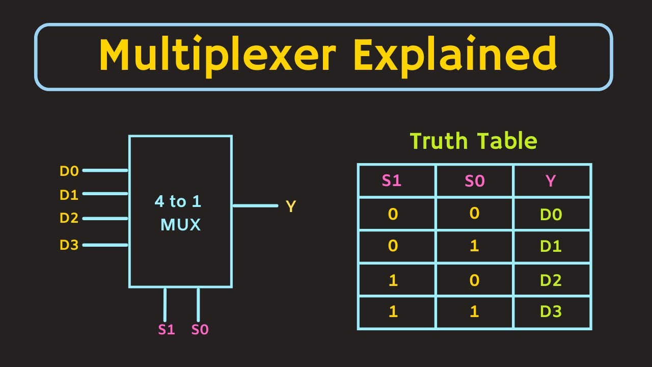
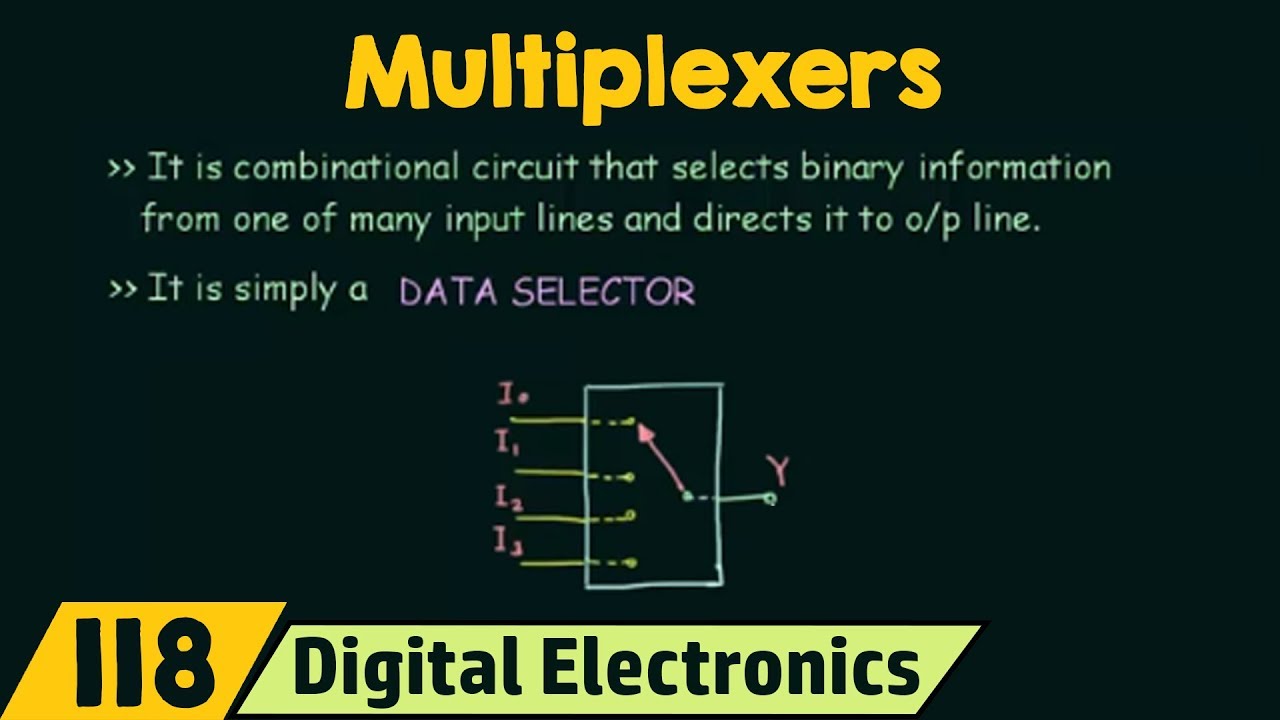
So, this result could also feed to the register b. So, either b is getting it from the external world or it is going to get it from a subtractor. So, whenever you have a if then else kind of conditions, so either it is coming from here or it is coming from here, from one of these places, so immediately what should strike to you is, we need a multiplexer there.
Because, this is going to take one of 2 values, either coming from the external world or something which is coming from locally. So, what I need is in some sense, I will need a mux and one of the inputs could come from the external world and the other one will had a figure out, where it should comes from. Similarly, for a, the input could come either from the external world or it could come from this operation a equals a minus b.
So, all I have done is, I looked at a and b, they are on the left side in four different locations. So, b is on the left side in two different places, a is on the left side in two different places. So, if I have as many places as a is on the left side, I will need that bigger multiplexer.
So, if I say a on the left side 4 times, I will need a 4 to 1 multiplexer, if I see a on the left side three times, I will still have a 4 to 1 multiplexer, because I cannot design a 3 to 1 multiplexer. In this case, a is either here either receiving external input or it is coming from this result of a minus b. So, if I put a subtractor here and let us say, this subtractor is going to give me a minus b.
So, I have to design the circuit, I have to do a lot of things to get the whole think working. But, if I have a circuit which can produce a minus b then either a or a minus b should be chosen, so that it goes to a. And similarly, if I put another subtractor, which can give me b minus a, then b can either take the value b minus a or it can take something from the external world.
So, we are taking one more step, in this step what we have done is, we are figured out that, it is not only the subtractors and comparators that are required, we also need and register and we also need some multiplexer. Now, let us see what else is needed, so for the subtractor, let us say, there are 2 inputs and you need to subtract one from the other. At some level, you need to take this line a, and connected to this and you need to take b, which is the output of this register and connected to this.
So, if this subtractor subtract whatever values are there on this input and subtract the right side one from the left side one, then if you supply a to the left side and b to the side, you will get a minus b. Similarly, the same subtracted design I can use only that, I will supply b to the left side and a to the side and that will give me b minus a. So, far what we have is, we have rudimentary setup, we have a rudimentary setup for not only what values are supposed to be kept where.
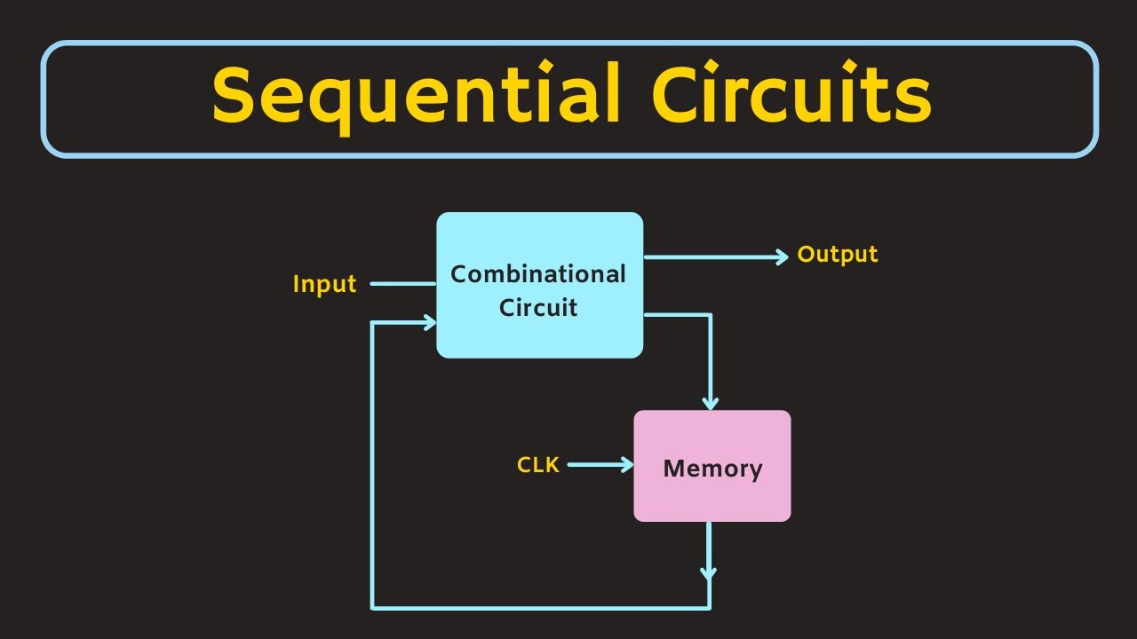
So, we have two registers a and b, which can either can take the value from the external world or it can take values from something local. So, you can see that, it is starting to resemble sequential circuit. So, there seems to be register and there seems to be a path that is coming through some combinational logic back to the register.
Similarly, something that goes through here, coming through some logic and coming back to the register. So, only other thing that we do not have is, there seems to be this need for a comparator, it suppose to take a and b, take a and b and you are going to need a comparator and this comparator is supposed to give three single bit lines. So, we are going to have this left side bit on if a is greater than b, the middle bit on if a is equal to b and the right most bit on, if a is less than b.
So, let us assume that, there is a black box called a comparator, which can do that. So, there will be 3 output lines and one of these output lines will definitely be on, because if we are given two numbers a and b, one of these should definitely be on. So, we seem to have various rudimentary things in place, there are few things that are still missing out.
So, I said a and b are registers and if a and b are registers, then I need some kind of clock and what not that coming in. So, that is bit understandable, so I need registers and registers need clock, it may need a reset signal and what not, so that is there. There is something else that is missing, which is what the muxes select lines.
So, these muxes have select inputs, we need to figure out, what this select lines are and this is not something that is coming from the external world. So, as a circuit, we need to be able to take the external inputs and these muxes select lines are not going to come with the external world. This in 1 and in 2 are inputs that are coming from the external world and somehow, if I am going to make a chip, then I need to ensure that, there is some correct sequencing that is going to happen.
So, these muxes need some select lines and so I will call these lines a underscore load for loading a and b underscore load for loading b. So, if a underscore load is 1, I am going to load from the external world, if it is 0 I am going take it from the subtract. Similarly, if b underscore load is 1, I am going to take it from the external world and if it is 0, I am going take it from the subtract.
So, the thing is, how do you get a load and b load and there are 3 output lines a greater than b, a equal to b and a less than b, somehow, we need to stitch all of this together, so that this circuit can be put in motion. So, right now what we have is, we have a circuit which is completely combinational, so we have various elements, but what we do not have is, in some sense the kind of marching instructions that have to be given. So, that we can move data from one place to the other, when to start evaluating this, when to stop evaluating this and so on, we do not have any of those.
So, we will see, how to do all of that in the next lecture. So, what we have done so far is, we have looked at the basic algorithm and which is on the left side here and we have come up with some kind of hardware diagram, which is on the right side. So, I am going to try and connect these two and come up with the complete description as a picture and we will take that picture and start writing verilog for that.
So, I will stop this video lecture here and in the next video lecture, we will see the notion of data path and the controller.


![Hands-On Power BI Tutorial 📊 Beginner to Pro [Full Course] 2023 Edition⚡](https://img.youtube.com/vi/77jIzgvCIYY/maxresdefault.jpg)


![Hands-On Power BI Tutorial 📊Beginner to Pro [Full Course] ⚡](https://img.youtube.com/vi/5X5LWcLtkzg/maxresdefault.jpg)