In both motors and transformers, when there is the possibility of operating at different voltage levels, it is very common for there to be a need to associate these coils in series or in parallel. It turns out that this association cannot be done anyway, I have to take into account the polarity of the coil. The polarity of the coil strictly depends on two things: the direction of the current and the winding direction.
To give an example: remembering the right-hand rule , if the current flows in this direction, the field rotates like this. If we have a loop, same scheme: current in this direction, field like this in the loop like this. Conventionally, the field goes from the south pole to the north, so this is the polarity of the loop, the same scheme with a coil.
In the coil we will have several turns. I have a coil with four turns, but I could cut it in half and make two coils with two turns each. If I wanted to return to the previous condition, to have something equivalent to a four-spike coil, I must associate these two coils in series.
But do I associate it with this terminal connected to that terminal or with this terminal connected to that terminal? We will have to follow the example of polarity. If the current had entered this terminal, the flow would go in that direction, that is, south here going north.
In this coil here I have, if the current is entering this terminal, the same scheme: south here going to the north. For additive association, that is, for this to be equivalent to adding the number of turns of one coil to the other, I have to have both coils, with their flux, pointing in the same direction, that is, the current has to enter here and you have to enter here too. This way, I connect this terminal to this terminal, the current entering here, is in series, will flow through these turns, will exit through this terminal, enter through this terminal and flow through the other turns, which is equivalent to having just a coil with four turns .
But, if instead of connecting them in series I connect them in parallel, I have the current entering these two terminals and I have the current leaving these two terminals. For current to be entering the same terminal, what we would have if they were in series, but now we have a current being divided between the two coils, which is equivalent to having a single two-turn coil with twice the section Circular. What if I reverse the direction of the association?
We have just seen that associating two coils in series, maintaining the same polarity direction, is equivalent to having another coil with the same number of turns as the sum of the two turns that were associated. So imagine: I have N1 and N2, I associate them while maintaining the same polarity and I will have the equivalent of another coil with the number of turns equal to N1 + N2. Now, if I associate inverted, the analogous is also true.
My result is equivalent to me having a coil with the number of turns equivalent to subtracting N1 from N2. To make our lives easier, the polarity mark was invented, which is a way of informing how we should make associations without having to take into account the current direction or winding direction. Let's take, as an example, an isolated transformer from 110V to 330V.
This transformer has a 110 Volt coil on the primary and three 110 Volt coils on the secondary. The polarity mark is represented by a dot at the top or bottom of each coil. These secondary coils will all be connected in series.
The polarity mark can also be interpreted as the positive sign of the induced voltage, through it we know the correct direction of association of the coils. If our primary we have 110 Volts, the polarity mark has to coincide with the positive pole. Remembering that this is an alternating current system, so this positive pole is simply an instantaneous value, as if we took a photo of the system at the moment the sinusoid was in its positive half cycle.
Considering that in this example all the coils are the same, the voltage induced in each of the coils will be 110 Volts. In this way, with the positive polarities coinciding with the point of each of the coils, we have an association of voltage sources and our voltage of 330V will then be generated at the secondary terminals of the transformer. Now let's see what would happen if one of the coils was accidentally inverted.
Let's keep the point in the correct location at the entrance. In the first coil we have the point in this location, here we also have the point and the last coil is inverted, that is, its point is downwards. We have 110 Volt inductors, here too and here too.
However, as this coil is inverted, the positive terminal downwards always coincides with the point. This way, the secondary voltage becomes 110V + 110V - 110V, that is, we have 110 Volts in the secondary. It is possible to evaluate this same problem using the number of turns instead of the induced voltage, so if each of these coils, which are the same, has N turns.
It would be as if this transformer here were equivalent to a transformer with N turns on the primary and, N+N+N, 3N turns on the secondary. In this situation here, it would be the equivalent of having a transformer with N turns on the primary and also N turns on the secondary. Following the transformer rule, if I have the same number of turns in the primary and secondary, the voltage in the primary will be equal to the voltage in the secondary.
Here I have three times as many turns on the secondary, 110V input and 330V output, 3 times more. But how am I going to assign polarity marks to the coils of a real transformer? The polarity mark is obtained by comparing two coils, let's take an example: two coils wound in the same direction, on the same leg of a transformer, they must have the polarity mark in the same position.
It doesn't matter if it is at the beginning or end of each of the coils, both will have to have the polarity mark at the same point. Polarity mark is different from polarity. When we talk about polarity, we are talking about North and South, when we use the concept of polarity mark it is precisely to avoid the need to think about north-south, because this is an alternating current machine.
So, when operating the machine, the coils are alternating from North to South at the mains frequency. So there is no reason for us to analyze it in relation to polarity. But what does the polarity mark do?
She always makes a comparison between the two coils. It will tell us: if one coil has north pointing in that direction, the other coil will also have north pointing in the same direction. How am I going to assign this brand?
I told you, now, that in our example we are wrapping a wire around a leg of a transformer. I can see the direction in which I am winding the thread, but on the real machine I can't see it because, in the vast majority of cases, it will be closed, it will be sealed. Or I could have the primary wound on top of the secondary and I can't see how the coils underneath are wound.
So I will need to do the polarity mark test so, through this test, I can make a comparison between a reference coil and the other coil. And then evaluate whether the two are adding or subtracting. Starting with the easiest situation, where I can see the direction of winding.
The assignment of the polarity mark will be a comparison between: this coil and this coil. So you have to choose one of the two as a reference, I'll choose this one, for example. If I power it with a sinusoidal voltage source.
If you placed a voltage V1 at its terminals, instantly, in the positive half-cycle, we would have a current entering here, so our flux is going from the bottom of the coil to the top, that is, we have a north here and north here. How will induction behave in this second coil? In the same way, he wants to enter here so that the flow can be maintained in this direction, from South to North.
Then the voltage induced at the terminals of this second coil will also have this instantaneous polarity, V2. This way, if I take my reference coil and assign it to polarity mark for it at this point here I have to assign the polarity mark for the second coil also at this point here. The positive, polarity mark.
Positive, polarity mark. But, as in a real transformer, I won't always have access to the winding diagram, the direction in which the wire is being wound, I can't do this type of analysis. So we have to develop a testing method.
Same scheme: I want to evaluate polarity mark by comparing these two coils. I feed one of them with a sinusoidal voltage source. But, in the laboratory, if I want to use this methodology, analyzing the positive or negative half-cycle of the voltage at the coil terminals, I would have to have an oscilloscope measuring these two terminals and these two terminals, which makes our procedure a little more difficult.
So what do we do? We associate our reference coil with the second coil. We associate them in series and then we measure the RMS value of the voltage at the other two terminals.
Place a voltmeter here. And I measure the voltage value. Here I have, for example, my V1, on these two terminals, I will have a V2.
This is equivalent to associating two voltage sources. I have V1 and V2. If this association was additive, the measured V will be equal to V1 + V2, if it is subtractive, it will be equal to the difference between V1 and V2.
But then how do we know whether an association is additive or subjective based on this test? At first, I might think that, if the measured voltage of the association of the two coils is greater than the voltage I applied to one of the coils, I would have an additive association. Everything leads us to believe that V is equal to V1 plus V2.
Right? But this is not always true because, if the second coil has many more turns than the reference coil, the voltage of V2 will be much higher than V1. So, in both additive and subtractive cases, the measured voltage V will be greater than V1.
Of course this is because V measures an RMS value so it will disregard a negative sign. Here is just a reference. This forces us to carry out a second test, now inverting the two terminals of the second coil, that is, we will have two tests and, necessarily, one of the two will be an auditory association and the other will be a subjective association.
Here, in the same way, I have my reference food, but now the association reverses the signs. In the same way, I will have an association of voltage sources and now I will be able to say what the polarity mark of my coils is. How do I do that?
I will have a measurement, here, which I will call Va and a second measurement, here, which I will call Vb. One of them is additive and the other is subtractive. Obviously, the higher value will be additive.
Let's assume that Va is greater than Vb, in this situation the configuration that measured Va represents the additive connection. And the configuration that measured the Vb, consequently, subtractive. As we saw, in the additive configuration we have this association of voltage sources and in a subtractive association we have this association.
So, if on our reference coil we place the polarity mark at this point, our reference is at V1, we have positive here and negative here. The point of our reference coil is connected to the non-point of our second coil, so the point is connected to the non-point. So we have the coil point at this location.
And the analysis can be done in the same way in the subtractive sense. The point of our reference coil is connected to the point of the secondary coil, that is, the point is connected to the point. The result of assigning the polarity mark must be the same, after all, we are talking about a table or coil with which the same tests were carried out.
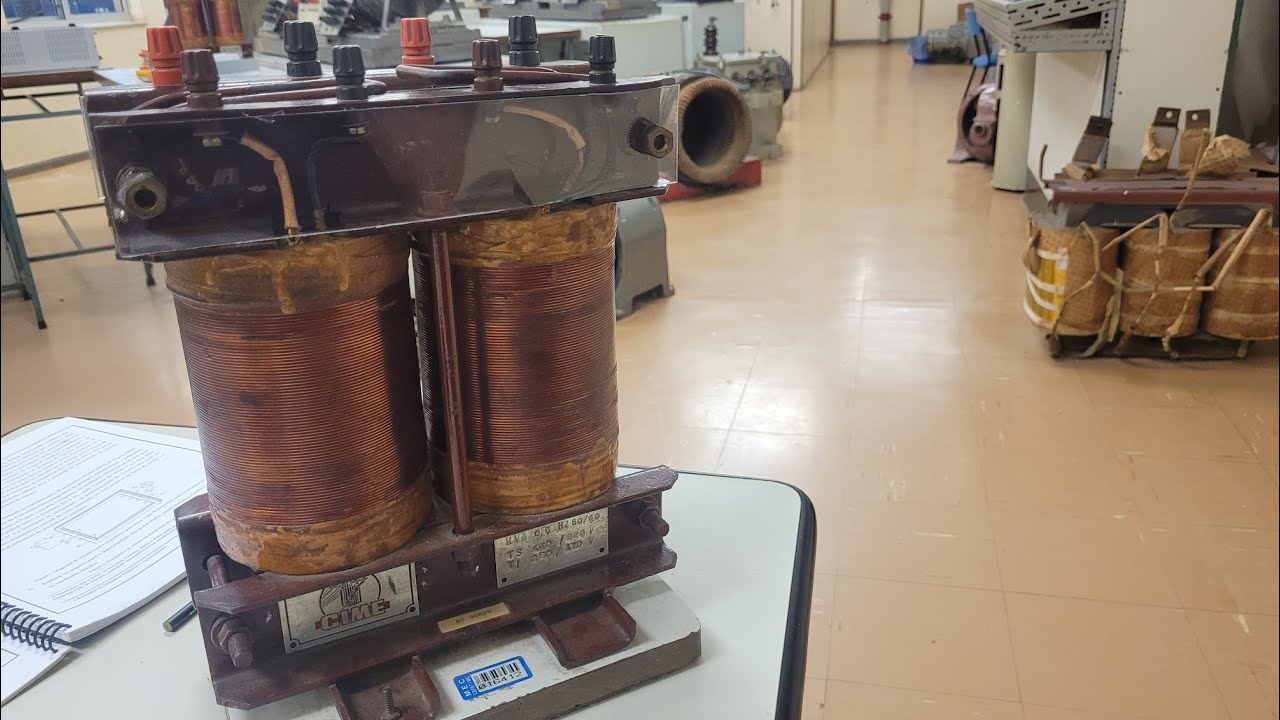
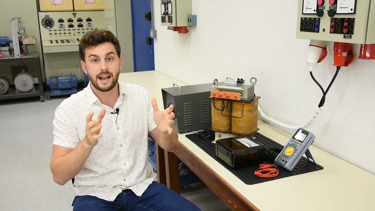
Let's do the test on this guy here to try to assign polarity marks to the two coils of this magnetic circuit. Here we are going to do two tests: in the first of them, we are going to supply the reference coil with a voltage of 30V. Let's associate this coil with the other coil and measure the voltage with a voltmeter.
In the second test it is the same thing as the first test but with the terminals of the second coil inverted. Here we have the two terminals of one of the coils and we have the two terminals of the second coil. We're going to use this coil here as the reference coil.
So here we have two terminals and we will plug them into our source. Remembering that, here, we have a variable autotransformer and it allows us to make a gradual power supply. Now we will associate our reference coil with the coil that we want to assign the polarity mark to.
Here I will do two tests: one associating at this point and measuring the potential difference of the association, that is, potential difference between this point and this point or I invert it, which is why I will use alligator terminals to allow this connection to be made quickly . This guy here will use it to measure the voltage that we applied to the reference coil and I will use the multimeter to measure the association voltage. Use the 30 volt scale, only add 30 volts, there is no need to add more than that.
Let's organize here. Let's bring our multimeter closer, here I'm going to place the reference terminal of our primary coil as a reference on the multimeter, here I'm also going to use a claw terminal to connect this guy and we measure the voltage. As I turn the cursor on our varivolt, I will start to put voltage on my reference coil and our multimeter here will measure the association of the reference coil with the coil that we want to mark the polarity of.
So we have here, basically, 108 volts. Now we are going to invert the association terminals. Now we practically have 168 volts.
So in the measurements: the first test gave us 108V and the second test gave us 168V, that is, higher voltage is the configuration where we have an additive association. And here, we have subtractive association. So let's put the polarity mark on our reference coil, we put the quality mark here and let's make our analogy with source association.
So in the subtractive I will have non point/point, point/non point and in the additive I will have and non point/point, non point/point. It has to give the same result in both analyses. I follow here no point/point, point/no point.
Here it will be not dot/dot, not dot/dot. So that was the polarity mark test method. It is important to always remember to pay attention to the machine's construction limits, voltage limit, current limit and always pay close attention.
We feed a coil, a single coil, it is our reference, then we associate the coil with a second coil, the one we want to mark the polarity and we measure the voltage of the association. Never the other way around. I will never power two associated coils.
This may cause some accidents. Beauty? Thank you and see you next time.