hello and welcome to my second tutorial about prepomex this time i will show you how to perform a torsion analysis in the software as an example i will use an elliptical bar subjected to torque just like before the first thing we have to do is to create a new model and select a unit system in this case i will use millimeters just like before and now since the new model is created i can import the geometry and also like in previous case i prepared the geometry in freecad and exported it in universal fire format for
for import to prepare max this is the step file here here and now since the geometry is imported i can create a mesh so let's go to the mesh tab meshing parameters and i will define a maximum element size of 15 millimeters now i will hit the preview button to see how the mesh will look like after it's generated and then i will confirm this let's create a mesh now it shouldn't take too long as you can see the mesh is now created and the software automatically switched to the second tab where we can prepare
the whole analysis this case i will start by creating a reference point for rigid body constraint and this is necessary because nodes of solid elements don't have rotational degrees of freedom and that's what i mentioned in the previous tutorial and because of that it's not possible to apply torque or enforce rotation directly to those elements however we can easily handle this by applying a torque using rigid body constraint and the other two most common applications of this constraint are modeling rigid parts and applying remote loads but in this case i will use it to apply
torque to this elliptical bar so let's create a reference point first we have to provide coordinates for this point and this will be located here and the default selection is the start of the of the coordinate system so i will just add the distance here to make this point appear at the other end okay so now the point is created and i can define the rigid body constraint this is available here and there are two types of constraints currently available rigid body and tie in this case i will use rigid body and the reference point
is already selected so i just have to select the region to which this constraint will be applied i will choose the face here and now i can confirm and the rigid body constraint is already created okay let's rotate the parts to the other side and now we can proceed to the remaining definitions now i will define the material just like before let's use elastic material properties this will be still again so i can rename it of course it's not necessary but it's a good practice so i will confirm this and now let's create a section
a solid section applied to this part right here so i will choose the part and confirm the section is already applied as you can see we have the constraint also defined so what we have to do now is to create the analysis step and this will be static step just like in the previous tutorial so i will use the the default selections here and now we have to create boundary conditions and loads which are necessary to simulate this let's start from boundary conditions in this case this will be just fixed boundary condition and the descent
here so i want to use the displacement rotation one even though i could use it and simply constrain the the three translations here this would be the same but it would be faster to just select this face and apply fixed boundary condition which will fix all the available degrees of freedom for this model okay let's do this and now we have the boundary condition defined let's rotate the model again to see the other end and i will define the load now in this case before we use pressure in this case i will use moment to
apply uh torque to this reference point so in this region type selection i will choose the reference point name and this will be automatically selected the only available reference point we have here and now i have to define the torque the conditions for for this analysis are shown here again i will also show this sheet later on because here are the analytical results but for now let's focus on the input data and so here we have the dimensions of this model material properties and torque necessary and to achieve the desired results okay so let's um
input the value here this will be in new times newton's time millimeters so i will provide the value in the correct unit okay let's confirm this and now this symbol here shows how the torque will be applied to the part now everything is defined we could submit the analysis and check the results but there's one more thing that i would like to do and i would like to show you since we already have the rigidbody constraint here we use it to apply the torque we can also use it for another purpose we can define history
output which is basically output for selected part of the model selected nodes elements or contact pairs this will be discussed later on and this history output is in form of x y plots you can you will see or actually tabulated data so we can request node output and select the if as a region type we can select the reference point and it will be highlighted here and as a variable to output you leave the default selection which is you that stands for displacements let's confirm this and then you will see how we can use this
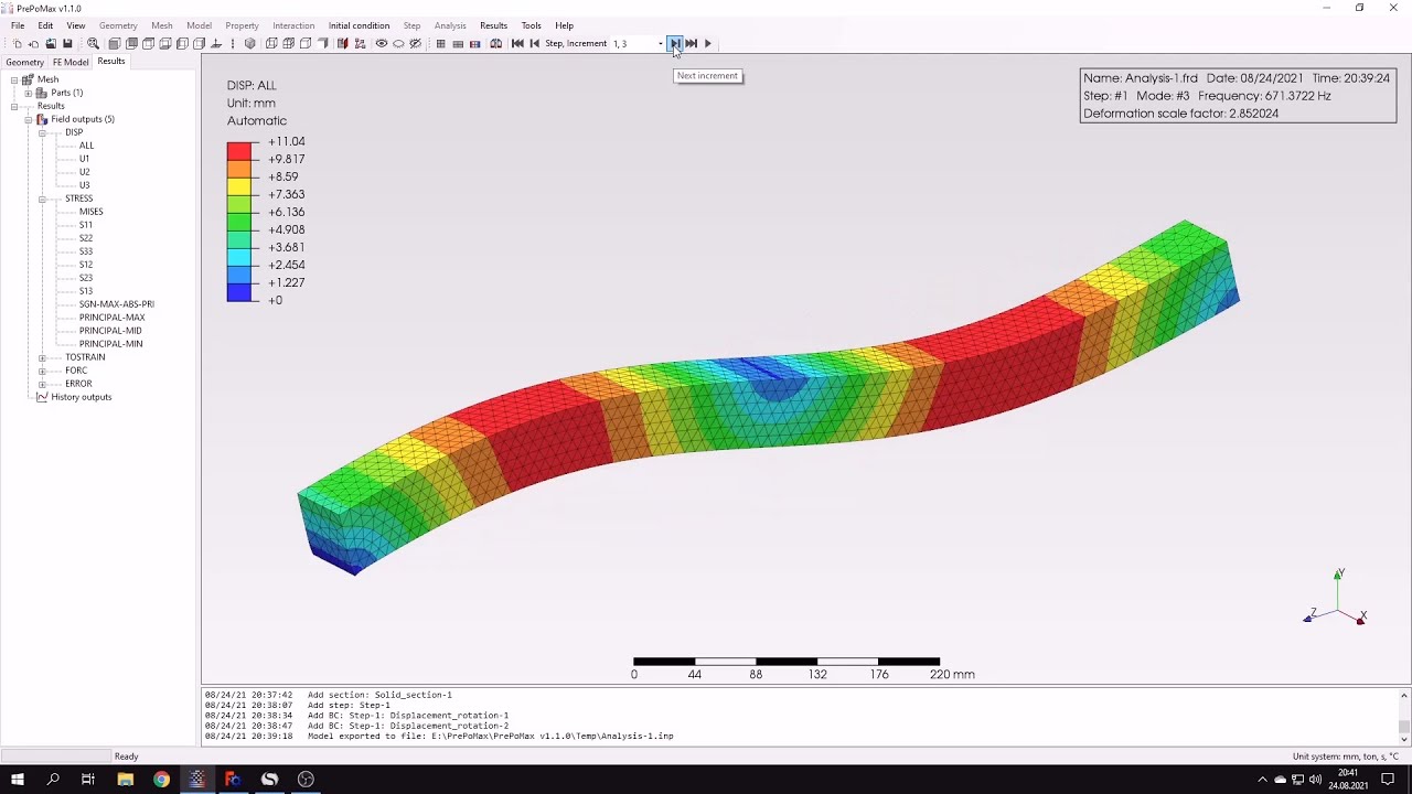
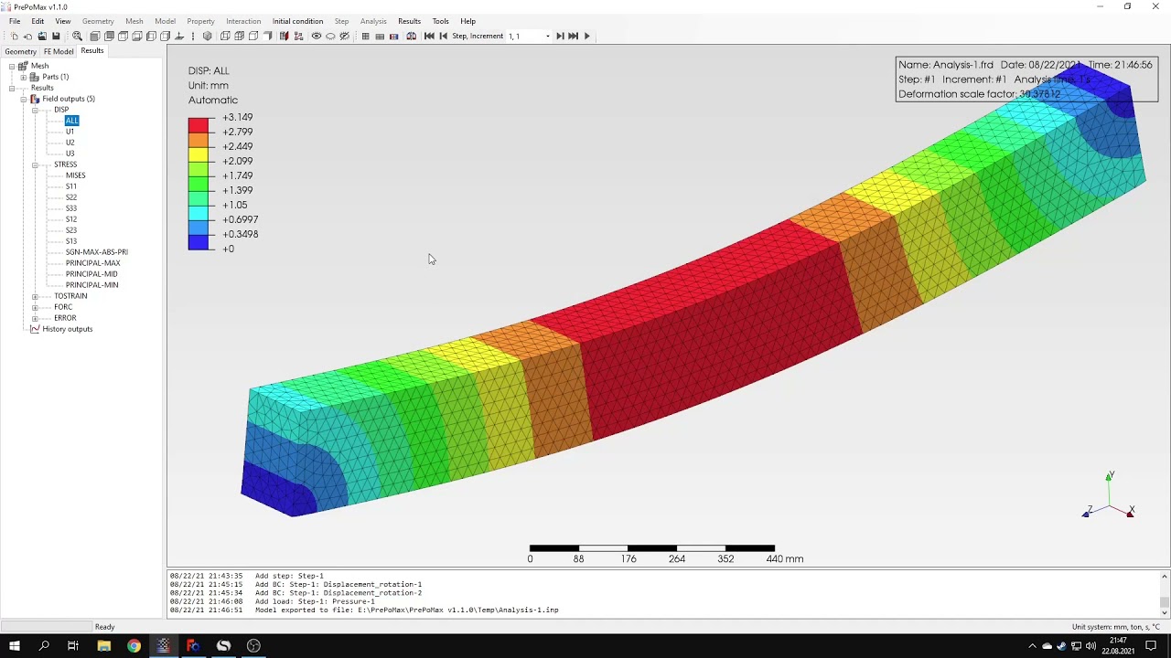
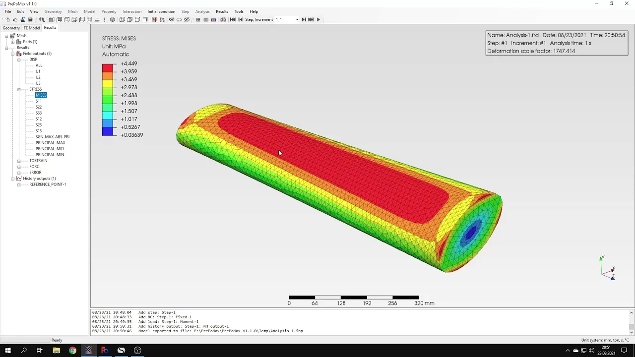
history output to obtain the angle of twist for this for this model everything is defined so i can submit the analysis now it shouldn't take too long because the mesh is not very fine of course in your case you can use finer mesh if you have a powerful computer and if you don't mind waiting a bit it's not a problem to use finer mesh you will get better results of course so it's already accomplished the analysis so we can proceed to results and here you can see the deform shape of the model and now let's
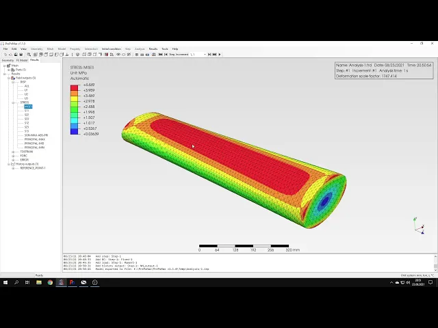
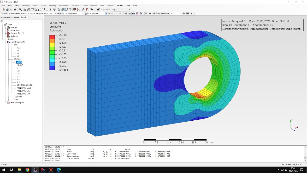
focus on the results let's verify them using analytical values so let's start from the stresses we could use default message traces but analytical solution is for shear stress just the one component of the stress tensor so let's go directly to the shear stress we can rotate the model and it looks better this way of course we could also turn off this this deformation deform shape it's not a problem to go to post processing and switch this to either true scale or completely off uh if you don't want to to see that it's deformed like that
or you can provide your own scale anyway here's the result of the shear stress and you can compare it with the value here is pretty close of course with finer mesh we could get even better uh convergence of the result but it's not necessary here i just want to show you that and the results are pretty good even with not so fine mesh okay so we verified the stresses and now i would also like to verify the rotation and angle with angle of twist it can be done directly because as i've mentioned that direct results
here of displacement you only have translational ones because of the limitation of solid elements that don't have rotational degrees of freedom but you can use the reference point which has the rotational degrees of freedom to output the angle of twist and when you when you extend this tab you will see that there are translation degrees of freedom as well as rotational ones we are interested in the rotational degrees of freedom in particular in this one because it's a z-axis so if you if we click this we'll get a single value for just the end of
the analysis and here's the value of the angle of twist and we can compare it with the analytical value which is shown here again you can notice very good agreement of the results it's almost perfect of course with some small small difference but it's typical for finite element analysis and their mesh dependence it causes stuff like that but for comparison with analytical values it's a really good really good agreement okay that's it for this second tutorial it was quite fast much faster than the previous one because in the previous one i also had to give
you some insight into the software and tell you something about prepomex in general how it works and and how it can be used and here i just wanted to show you one of the most common types of analysis and actually one of the most misleading types of analysis because people often wonder how they can perform such analysis in in fva software and due to those limitations of of no boundary of solid elements nodes they don't know how to apply torque which is very common issue and actually in some of the open source codes it's not
possible to do this to applying rotation and torsion to to model this like that but in prepayments and calculus it's not a problem you can easily model this using rigid body constraint which is very handy anyway and that's it for this second repo max tutorial thank you very much for your attention in the next videos i will show you the other features of this software feel free to ask any questions and suggest topics for future tutorials in the comments and also have a nice day and see you in the next video