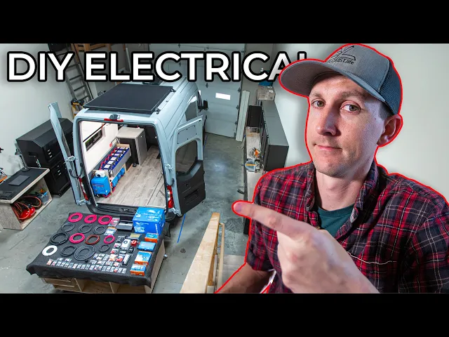
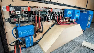
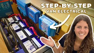
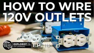
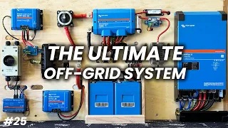
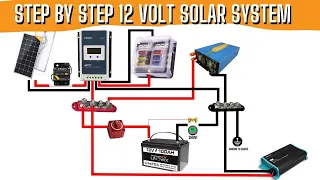
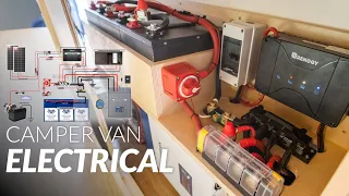
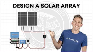
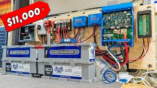
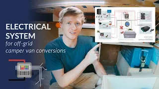
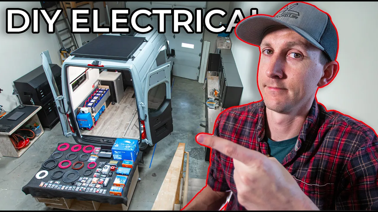
Hey everybody it's Nate from explorers. life I teach people how to build DIY campers and in this video I'm going to show you start to finish how I installed this complete DIY electrical system in this Mercedes Sprinter camper van this video is going to cover building the wood frame wiring the battery Bank the lyns distributor the chassis ground the multiplus inverter charger the 120 volt AC distribution panel the 12volt DC Distribution panel Shore power solar charging and alternator charging and if at any point in time you want to jump straight to one of those sections
I put timestamps in the video timeline below so you can do just that now two things before we get started first there are a ton of other resources that accompany this video like wiring diagrams parts list plans 3D models and all kinds of other fun stuff that you'll probably want to check out and those are in the Video description now secondly this video is also kicking off the brand new explorers. lifee store which features the wiring kits that you'll see in this video now if you've been around for a while you've seen our parts list
and they were admittedly excessively long and when pushing all of you guys to Amazon we had no control over quality or them keeping items in stock so Steph has been hard at work sourcing the parts and components required so that we could Bring all of this inhouse and make sourcing all of this stuff way less painful for all of us now enough with the sales pitch let's get started every project should start with a the plan so the first step we did was to figure out exactly how much space we had to work with we
had a space that was about 5 ft long by 2 ft high with a wheel well right in the middle and we wanted to make sure that this enclosure was as narrow as feasible now you'll notice I Had a level in there now I wasn't using it as a level necessarily using a level in a van doesn't really work because the floor we're working off of is often unlevel and the van is pretty much guaranteed to be unlevel and the unlevel of the van will change as more weight gets added to the van I was
only using the level as a straight edge here next we took our measurements upstairs to my office and started modeling out all the details in SketchUp I had a pretty good Idea of what I wanted this to look like but recently I've really enjoyed making these projects digitally so that I have a plan when it comes time to fasten the boards together with a complete plan in SketchUp now I know what size to cut the boards how they'll attach together and I can double check all my measurements ahead of time and Export a cut list
for the project so I can cut my plywood efficiently with minimal waste next it was time to start cutting plywood so I Laid my piece of 2in foam board insulation on top of my workbench to act as a support for the board while using my circular saw now if you've never used a piece of foam board like this to support your sheet Goods while breaking it down into smaller pieces you should really consider trying it because it really makes the process super easy now for this project I'm using a 5tx 5T piece of 3/4 in
Baltic birch plywood using my cut cut list I exported from The SketchUp file I used my cordless circular saw with a straight edge guide to make all my initial cuts and then once I had the plywood broken down into smaller more manageable pieces it was time to get the table saw set up for some more accurate Cuts now I cut everything pretty much a qu inch too big so that I could run it through the table saw to make the cuts just a bit more accurate which is totally optional but it's just something that I'm
practicing With as I'm trying to get a bit better at woodworking next I took the boards over to the miter saw to cut them to length my boards were a bit too wide to cut them all the way through in one pass of the miter saw so I had to set up a stop block make the first cut and then flip the board over to finish the cut now a sliding miter saw would have fixed this problem but alas I don't have one so this is how you tackle this issue if you're like me and
you just have a Standard miter saw and lastly I finished up a few of the smallest boards over on my Crosscut sled on the table saw next up was running my sander over all of the boards s the boards were already pretty smooth so a quick pass with some 280 grit sandpaper was sufficient for this project for now now that the boards were all cut apart it was time to put them back together using the 3D model from the SketchUp file I used tight Bond wood glue on all the edges with a few 1 and
A/4 in brad nails with my nail gun to line everything up and then finish the joint off with screws with the help of my Craig pocket hole jig once the structure was complete I wanted to go ahead and Mark where everything was going to go and pre-drill the pilot hole most of the components use either number 10 or number 14 screws so I laid out all the components and made my way around the enclosure with an E8 inch bit and a 532 inch bit drilling my pilot holes as Well as some of the bigger holes
where the wires would need to go through the cabinet in a few strategic places I wanted to clean up the wire holes with some grommets so I grabbed the measurements for those and being impatient and not really wanting to wait a few days for shipping I decided to just 3D print them so a few minutes on SketchUp later I had a 3D file and then I let the 3D printer do some work printing the grommets while I went back Downstairs to work on the next step now although the edges of the Baltic Birch were actually
really pretty in my opinion sometimes it does make it look unfinished when it's left like that so Steph decided for me that we should finish off the edges with some Edge banding now if you've never heard of edge banding it's simply a really thin piece of wood or veneer that has heat activated glue on the back of it to install the edge banding we literally Just iron The Edge banding into place the iron melts the glue where it then seeps into the wood and the verer and then when it cools it sets up nice and
sturdy The Edge banding is a bit wider than the plywood and they make an edge banding cutter but I don't have one yet and so I just use a wood file to take the edges down a few quick Strokes with some with the sanding sponge and we were good to go and the edge banding was all finished up and we put Edge banding on All the exposed edges the top Edge is getting a lid so we left that without the edge banding on purpose next it was time to finish off the woodwork so I gave
one final sanding to knock down some of the scuffs and splinters it had after drilling the pilot holes from earlier and then starting putting the finish on for this project I'm using Minwax paste finishing wax which pretty much just get smeared on and then rubbed in with a rag it's a little orange at First but once it soaks in and dries it's pretty much completely clear and doesn't really change the color of the wood at all Leslie is planning on using Baltic Birch countertops for this fan so this enclosure would match the countertops when somebody
opens the bench seat where this enclosure will live once the full buildout is complete next up is making the battery tray and tie downs where the batteries will sit I cut four pieces of 1 in by 1 in aluminum Angle that would fit on all four sides of the battery bank I used the miter saw for this piece with a 2x4 on top just to hold the angle in place nice and tight aluminum is a soft metal so it's fine to cut with a standard wood blade just go slow be careful and wear eye prediction
and keep your hands clear once the metal was cut I drilled some holes with a counter syn bit so the tops of the screws would sit nice and flush with the aluminum rails once installed the piece Of angle that was going to sit at the back of the battery Bank was also going to hold down one side of the can buckle lashing straps that I'm using to secure the batteries in place from the top so after wrangling the loose straps I secured the angle in place with some number 10 by 3/4 in wood screws with
a screw through each of the strap I put the batteries in place to get some accurate measurements screwing the rails to the enclosure as I went and then once I had a good measurement for how long the battery bank would physically be I fastened the end Rail and then secured the two strap tie downs just outside of the last rail for our battery straps then giving it a quick test and a teaser into the next chapter I put all of the batteries into place and cinched the straps down to make sure everything fit as I
wanted to and blessed it with a that's not going anywhere now remember the grommets I printed earlier now was Time to go ahead and put those into place a bit of superglue on the back of each one put into the hole and it was good to go now the flange on this particular gret is much larger than the rest and the only reason that I did that is because whenever I was drilling that hole my hole saw tried to eat my hand and it chewed up the wood in the process now I didn't want to
waste time and maybe more importantly wood uh so I simply decided to make The Grommet trim Just a bit bigger to cover up that happy little accident and that's pretty much it here's a look at it before I get it in place into the van I'm really happy with how it turned out and I think it's going to make a great structure to hold all the electrical components that I'll be installing in this van going forward the glute and pocket holes hidden on the back side make this structure incredibly strong and we have no problem
with standing the abuse of traveling down Rough roads and I'm especially happy with the straps and the battery tray as I've historically left the straps and stuff until the very end which ended up being a bit of an afterthought building this into the initial design gives us a good plan for battery security from the very start next I move the enclosure into the van and slid it into place and I'm really happy with how it turned out excited to start some of the actual electrical work on the enclosure slid The lid into place and secured
the top with counter sunk wood screws that can be easily removed for access to the batteries in the main system fuse as needed now that the enclosure is built it's time to move on to the next step in the process which is wiring the battery bank and that's coming up next now that the frame is built it's time to move on to wiring the battery Bank the parts used in this section of the build come from the Explorer life battery Bank Wiring kit which includes everything you need to connect up to six batteries together using
four out wire it includes 5T of red 4 out wire 5T of black 4 out wire 20 4 out X 5/16 inch wire lugs 10 pieces of black 1in heat shrink and 10 pieces of red 1in heat shrink I measured and cut 7in long pieces of wire from each 5ft section which is five pieces of each color and this is a good length of wire to go from one 100 amp battleborn B to the next when they're positioned side By side now there's a bit of extra wire in the exploris life battery Bank wiring kit
for you if you're using different batteries or if you just need a bit more length for a different configuration next I use those same Cutters to strip back 7/8 of an inch of insulation from each end of the wire and then I clamped my crimper to the table and I started crimping the 4 outx 516 inch wire lugs onto the ends of the wire and now that the lugs were crimped to each end of the Wire nice and secure it's time to finish off the wire with some adhesive line heat shrink this heat shrink has
a layer of heat activated glue that melts when it's heated up and seals off the connection from any kind of moisture as well as adding a bit of additional strain relief to the lug now that the wires are all cut stripped crimped and heat shrink together it's time to move the batteries into place and wire them into a battery bank I move the batteries Into place in the battery tray of the enclosure and tighten down the strap to hold them nice and secure then I vacuumed out the dust and dirt that had accumulated near all
the battery terminals of the batteries Then I wiped all the battery terminals down with a bit of alcohol which cleans off any grease dirt grime anything like that that ends up on the terminals and gives a better electrical connection and then I did the same thing With the wire lugs this is also a good time to verify that there's no burs or rough spots on the lugs and knock them down with a bit of sandpaper if needed these particular lugs were all good to go so a wipe down with some of the alcohol on a
rag was all they needed and finally I bolted everything together with the bolts included with the battleborn batteries they include a stainless steel bolt with a nlock nut so it should never come loose I worked my Way down the line on both the positive and the negative terminals putting the lugs bolts washers and nuts in place I only hand tightened everything initially and then came back with my impact driver and a wrench to Snug everything up lastly I made a pass with my torque wrench to get everything up to proper spec every battery manufacturer has
its own recommendations on torque specs but for battleborne it's 11 foot-pounds now it's important to notice how I Oriented the lugs onto the battery terminals when a battery terminal gets two wire lugs on it the lug should go on the same side of the battery terminal this is so that each battery can simply add power to the wires instead of having the full brunt of the power of the entire Bank flowing through a battery terminal wiring it like this makes it less likely for heat to build up on a battery terminal as the biggest bulk
of the power is flowing through the lugs And wires and not through the battery terminals now there are different ways to wire battery Banks but this method is the one that I find to be the easiest and uses the least amount of Parts this method is one of the four correct ways to wire a battery Bank according to the victron wiring unlimited book now that the batteries have been wired into a battery bank it's time to move on down the line and wire the battery Bank to the lyx distributor and that's coming up Next now
that the battery bank is wired it's time to connect that to the victron links distributor here's a list of the components used in this section of the build the victon link distributor and the Explorers Life lyx distributor wearing kit which includes the victron BMV 712 battery monitor wire wire lugs heat shrink an ANL fuse and fuse holder links adapters a master battery disconnect Shunt and switch spacers a butt splice connector and some assorted screws and Hardware the first step is going to be mounting the shunt so I grabb the victron BMV 712 12 battery monitor
box I thoroughly read through the instruction manual so I fully understood how this thing worked and then I grabbed the shunt I also grabbed the shunt spacers and screws from the exploris life links distributor wearing kit I already had the shunt positioning pre-laid out like I showed in the enclosure build part of this series so mounting the shunt was simply a matter of screwing the shunt to the wall with the spacers in between now this was just temporarily mounted for the sake of taking a measurement for now I took a measurement for the negative wire
that will go from the shunt to the battery bank now wires exiting the battery Bank should be on opposite ends of the battery bank so I stretched this wire to the furthest battery in the bank Made my mark and then moved over to the workbench to cut strip crimp and heat shrink a 4X 5/16 inch wire lug onto the end that would attach to the battery bank and a 4X 38 in wire lug onto the end that would attach to the shin next was moving on to the positive wire that goes from the battery Bank
to the lyx distributor now before the positive wire gets to the lynx distributor it has to go through the main system fuse as well as the main battery cutof switch so I started measuring cutting crimping and heat shrinking lugs onto the 4 wire the battery and fuse connections get a 4 x 516 inch wire lug and the battery shut off switch gets a 4X 38 in lug now now if you got a sharp eye you'll notice that I'm installing a battery switch rated to 300 amps continuous and a 400 ampl fuse now this is fine
because abyc standards allow us to use a fuse size that's up to 150% of the Max rated ampacity of the wire and the switch Falls into the same category 150% of 300 amps for the switch is 450 amps so our 300 amp continuous switch is within abyc parameters for a 4 amp fuse the switch is sized based on the actual load that we anticipate pushing through it the multiplus 3K that we'll be installing in this system will pull no more than 250 amps through this switch and that is running pedal to the metal and the
thing to the floor which will rarely happen that gives us an additional 50 amps for 12volt DC appliances which we will never do under continuous Usage Now if you plan to run your 3,000 watt inverter at Max Capacity continuously and use more than 50 amp DC power continuously all at the same time you're probably going to want a bigger switch with a higher rated current but in all honesty you're probably going to want a bigger system than this anyway if your electrical demands are that high now you'll also notice that I made the linear distance
From each end of both of these wire runs identical taking the fuse switch and shun links into account now this is important so that the battery Bank drains and charges evenly since each wire will have as close to identical resistance as we can possibly get or at least how that's how it's going to work on paper now let's put all this stuff together I wiped all the wire lugs down with some alcohol on a rag to clean them off and started mounting components and Making connections negative wire to shunt links adapter to shunt and shunt
to wall remembering to put the shunt spacers between the shunt and the wall also notice the direction of the shunt here there's a battery side of the shunt in a loads and Chargers side of the shunt so the direction this is installed does indeed matter and then the positive wire to the switch the links adapter to the switch and the switch to the wall now there are spacers for the battery Switch in the Explorers life links distributor wearing kit that go between the switch and the wall the input versus output markings on the back of
the switch they don't matter in fact the input versus output will actually change depending on if the batteries are charging or if they're discharging next I lined up the links distributor and screwed it to the wall then I fastened both the links adapters from the switch and the shun to the lynx distributor in A bolt washer lyx adapter lyx distributor washer lock washer nut kind of fashion then I connected the wire from the switch to the fuse holder and then I screwed the fuse holder to the wall and then I connected the wire from the
fuse holder to the battery Bank looping the excess down between the battery and the enclosure now I would have loved to have cleaned up that Loop and made it shorter but like I mentioned earlier keeping the positive and Negative wires the same length means that there had to be excess wire somewhere which was unavoidable but it's electrically correct so I'm obviously fine with it and then after that I connected the negative wire from the shunt to the battery bank and I saved this to the end just so the wire was out of the way while
I was trying to mount the fuse holder and such and then I moved onto the power wire to connect to the shunt this little power wire Powers The little computer board on the side of the shunt for the BMV 712 that also sends power to the display gauge I connected this wire to the furthest stud on the right of the link distributor and this means that power to the BMV 712 will be disconnected when the main system switch is turned off now if you want the BMV 712 to stay on all of the time you
would want to connect this wire somewhere on the battery side of the switch now this is personal preference There's really no wrong answer here I like to be able to turn off the whole entire system with no loads running for the sake of system storage and that's why I personally like it like this now the power wire that's included with the BMV 712 is way too long for our purposes so we added a butt splice connector to the Explorer SLI links Distributor wiring kit so that we could just cut the wire down to make a
more appropriate length and to do that I just cut the Wire after the fuse stripped each end of the wire back a bit crimped each side of the splice connector and then melted the adhes of lined heat shrink and then plug the feral into the B1 terminal on the shunt the data cable for the BMV 712 was already run through the walls so I just grabbed one in and connected it to the shun then I moved up to the gauge where I drilled a hole with my 2 and E in hole saw and mounted the
gauge into the hole the other end of the data cable that we Just plugged into the shunt goes into the back of the gauge like so lastly I bolted the main fuse in place and turned on the master switch and we have power now it was time to open up the victron Connect app update the firmware and change the parameters to match our system which I'll leave a cheat sheet to that um in a blog post that accompanies this video you can find a link to that blog post in the video description below this video
and then finally I put some Zip ties and cable clamps on the cables for some cable management and put the covers for the various components back into place now that this step in the project is all finished up it's time to move on to the next step which is connecting the chassis ground from the body of the van to the linkx distributor and that's coming up next now that the battery bank is wired to the linkx distributor it's time to wire the chassis ground for this section of the Install I'm using the explores life chassis
ground wiring kit which includes some wire wire lugs heat shrink a bolt a nut washers a lock washer and a serrated washer now I'm actually going to show you two ways to make this connection because the van that I'm actually working on here has a pretty specific best way to connect the chassis ground but it's not particularly common so I don't know how useful that will be so I'm going to cover the more common way With a benchtop demonstration here now pretend this piece of metal is a body support rib typically I would drill a
hole into any of the body support ribs or any other solidly attached piece of metal with a 5/16 inch drill bit and then I would put a washer onto a bolt and then I would put that Through the Wire lug and then I would put the serrated washer on the bolt and then I would put the bolt through the body support rib and then on the other side I'd put a washer a lock washer and a nut and then tighten all of that up the serrated washer would cut through any paint into the metal giving
us a good grounding connection now depending on which code or standard you're looking at this serrated washer is either adequate or inadequate for making the grounding connection so the other alternative would be to scrape the paint down to bare metal and apply the wire lug directly to the metal with no Serrated washer so do with that information what you will you now have options for if you're trying to mirror this install now the walls of this van are already installed and I didn't want to take them down just to get to a body support rib
but there was a plus nut right there so I'm using that now fortunately it was inset into the hole a bit which meant that I had to modify a wire lug to fit now normally I don't like bending wire lugs but since it's Just for a chassis ground wire and not an actual power wire I'm fine with it a bench vice and a stout screwdriver and we had a wire lug that would indeed fit I crimped that lug onto a 4 out wire and secured it in place with a washer a lock washer and a
bolt and then I slid the frame back into place and bent the wire up and around and connected it to the front of the links adapter where it connects to the negative bus bar of the linkx distributor now this wire has to Be so thick because abyc says that the chassis ground wire can be no smaller than one size smaller than the biggest wire in the system and since we're using 4 out wire for our other connections that means that this wire could be no smaller than 3 o but for the sake of consolidating wire
sizes and lugs we opted for 4 here this large of wire is so that if there's a direct short with the chassis there's a return loop back to the battery Bank rated to the full Ampacity of the current carrying conductors in the system so that the circuit could complete and the main fuse would blow thus protecting the system now that this step in the project is all finished up it's time to move on to the next step which is connecting the victron multiplus inverter charger to the links distributor and that's coming up next now that
we've wired the chassis ground it's time to wire the victron multiplus inverter charger to the Victron links distributor here's a list of the bits and pieces used in this part of the install the vicron multiplus 3K inverter charger and the Explorer life 3K multiplus wearing kit which includes 4 red wire 4 black wire wire lugs heat shrink a 400 amp Mega fuse the ve bus smart dongle an RJ45 UTP data cable and some mounting screws and Hardware the first thing to do was to mount the multiplus inverter charger which comes with a backer plate for
hanging I used Five wood screws from the Explorers life multiplus wiring kit to mount this hanger plate to my frame and then I hung the multi Plus on the hanger plate and then after that I secured the bottom of the multi plusus with two pan head screws into the bottom of the multi plusus next I turned off the master battery switch and removed the cover of the multiplus and the lyx distributor and then I got busy cutting stripping crimping and heat shrinking the big four Out wires that would go from the lyx distributor to the
multiplus there was a positive wire a negative wire and an equipment ground wire all of which got four by 516 in wire lugs I wiped down all the electrical lugs with some alcohol to clean them off so that they make some good electrical connections and then I took the nuts washers and lock washers off of the victron links distributor and pulled off these little separator flaps Just to get them out of the way they simply snap in and out of place next I'm making my multiplus equipment ground connection this one goes to the center stud
of the negative bus bar bar in the victron links distributor the other side goes to the little equipment ground stud on the bottom of the multi plusus inverter charger with the order going multi plusus serated washer wire lug washer lock washer and nut and then tighten it All up next was the negative connection going to the multi plusus I put that on the far left stud of the negative bus bar inside of the victron links distributor and tighten down the hardware and then I cleaned off my 400 amp fuse and put it into place on
the positive bus bar then I put the positive wire lug in place and then tighten down the washer lock washer and nut on both the top and bottoms of the mega fuse to their proper torque and after that I Connected the positive wire to the positive terminal on the multiplus and then I fought with the negative wire for a minute and finally got into in position and tightened down hindsight being 2020 I think it would have been easier to wire the multiplus side of these wires first but it doesn't really matter electrically do with that
information what you will next I'm going to wire the ve bus smart dongle so that we can Bluetooth into the multiplus and Turn the unit on and off from our phone and set the proper Shore power input current limits using a tiny screwdriver I connected the red wire feral to the battery positive terminal and the black wire feral to the battery negative terminal of the ve bus smart dongle and then I connected the positive wire lug to the positive terminal of the victron multip plus and then connected the negative wire lug to the negative Terminal
of the multi plusus then I plugged one side of the RJ45 UTP cable into the ve bus smart dongle and then I cleaned off a smot underneath the multi plusus with some alcohol pulled off the double-sided tape cover and then stuck the ve bus smart dongle into place just right underneath the multipl and then I ran that RJ45 UTP cable up into the multiplus and plugged it into one of the ve bus ports on the far left side and it doesn't really matter which one you use They'll both work just fine now with all cables
in their proper places with positive wires connected to positive Terminals and negative wires connected to negative terminals I could turn on the main battery switch which would delivered 12vt DC power to the multi plus and then I could turn the multi plus switch up to on and then I could hear the multi plusus click on and then use my multimeter to see that I did indeed have about 120 volts between the Hot and neutral AC output number one Terminals and then I could open up my victron Connect app click on the vbus smart device which
is the multiplus update the firmware as necessary and then see that we are connected and that the inverter is indeed inverting 12vt DC power to 120 volt AC power as intended nice we can use the app to then turn the multiplus off and then back on as well as set our input current limit now the input current limit is Simply telling the multiplus what amperage of shore power that you're connected to so that the multiplus knows not to pull any more power than that preset amount so that you'll never accidentally trip the shore power breaker
and the multiplus will pull any overages from the battery Bank this is called power assist and I'm going to explain that more in depth in an upcoming how this system works section of this installation series now if you Actually need to program your multi plusus you want to use the victron MK3 USB dungle and then run a wired USB connection to a laptop or an Android phone through an on the- go cable to the vebs connection on the multiplus and then open The victron Connect app changing the settings in The victon Connect app for the
multiplus is reserved for victon trained professionals only so there is a password for this section and the Password for trained professionals is zzz but if you aren't a trained professional you can't use that password you just can't do with that information what you will but since I'm a trained victron professional I can show you that this gets you into the extensive victron multiplus programming options now we aren't going to dive into this in this video because this multiplus was purchased from battleborn and when you purchase batteries and a multiplus from Battleborn it gets pre-programmed for
you so you don't have to mess with any of this stuff so since all of this is pre-programmed for us we are good to go and now we're all wrapped up the multiplus is now connected to the links distributor and the vbus smart dongle is connected to to the multiplus now it's time to make it so that we can use some of this power by connecting the multipl plusus to the 120 volt AC distribution panel and that's the next step in this Series so stay tuned now that we wired the victron multiplus inverter charger to
the links distributor it's time to wire the multipl plus to the 120 volt distribution panel here is a list of the components used in this section of the build the 120 volt AC distribution panel and the explores life 120 volt AC distribution panel wiring kit which includes six gauge Triplex wire six gauge insulated ferals a 50 amp main breaker a wire gland and the screws to Mount the panel now before I got started I checked to verify that my battery disconnect switch was off and I also checked with my voltage sensor that I had no
120 volt power coming out of my multiplus and it was safe to work on the first thing to do was to prep the 63 wire I stripped 4 in of the outer sheath off and then I put some 1in black heat shrink around the cut to clean up the edge and add a bit of extra protection and then I took the wire Gland from the multi plusus and slid the wire gland into place with the help of a drop or two of Dawn soap and tighten down the gland and yes this entry gland is too
small for 63 wire victron knows how big of a pain this is and has it penciled in in the next revision of the multi plusus to fix this but until then this is our solution next up I put three wires into my table Vise with the white wire in the middle now this is helpful because it Holds the wires flat across for easy measuring since we're trying to put these wires from a round sheath into wire terminals that are flat across inside of the multiplus then I measured out and stripped back about 5/8 of an
inch from each wire and then I crimped a six gauge insulated feral onto each one next with ample amounts of wiggling and a modest amount of cussing I use my needle-nose pliers to help guide the three wires into place black white white And green to the line neutral and ground terminals respectively once they were fully seated I tightened up the screw terminals to their proper torque specifications and then tightened up the wire gland on the bottom of the multiplus tighten it with your fingers the best you can and then a flathead screwdriver helps get it
just a bit tighter just be careful don't stab yourself actually for liability reasons I don't recommend you doing this just This is just what I did next I secured the wire up and out of the way along the upper back corner of the box now after that was time to open up the AC distribution box and cut away the hole for the wire gland and fasten the wire gland into place and this one is one we specifically chose for the explores life 120 volt AC distribution wiring kit so we could make 100% sure that it
fit I stri back the sheathing on the 63 wire and put it into place inside of the wire Gland next I fed the five 120 volt Branch circuits into the distri tion box and then I screwed the box to the wall next it was time to wire up all of the wires inside of the 120 volt AC distribution box so I started with stripping back the insulation on each of the triplex wires I took a picture of these circuits before I cut off the sheathing so that I could remember which was which when it came
time to label the circuits on the panel the first thing Here was snapping the breakers into place there's a little notch on the bottom of the breaker that just sits on the lip in the middle of the panel and then tilts up into place with the positive bus bar going into the slot on the back of the breaker this breaker box has two sides we're only using one side in this application with the tandem Breakers I'm using we can actually get eight different circuits on this one side which should be plenty for any Camper van
the other side is reserved for campers with 50 amp sh power service with two hot legs incoming or for powering circuits from the multiplus AC out 2 which is for circuits only powered when sh power is connected now I put a few use case scenarios for the two sides of this distribution panel on the product page for this distribution panel to help clear this up after that I simply started working my way down the circuits putting a feral on each one and Then inserting the green wires into the ground bus bar at the back and
the white ones into the neutral bus bar at the front I recommend doing all the green ones first and then doing the white ones it just helps keep things organized and finally the black wires go up into their respective Breakers the six gauge goes into the 50 amp main breaker in and the power goes out to all of The 100 20 volt Branch circuits through each of the 20 amp tandem Breakers and the 12 gauge Triplex wires that was already run in this van and here's how a look at the panel looks all wired up
now I can screw the lid to the panel and then print off some labels with my label maker and put those into their respective slots on the front of the panel next I can turn all the breakers on turn the main battery switch on and then turn the multiplus on and we have power that's always a good feeling now that we have power to all of our volt Branch circuits throughout the 120 volt distribution panel let's keep going with this theme of 120 volt power and connect our shore power and that's coming up in the
next section of this series so stay tuned now that we've wired the 120 volt distribution panel it's time to wire for sh power all of the components in this section of the build are part of the explores life 30 amp Shore power wiring kit which includes 10 gauge Triplex wire 10 gauge insulated Ferals a 30 amp sh power Inlet and a 30 amp sh power cord the first thing to do was to wire the tin gauge Triplex wire to the back of the shore power Inlet I loosened the strain relief bar and then fed the
tin gauge Triplex wire up through the back then I stripped off about 3 in of the outer sheathing of the wire and then strip back about 5/8 of an inch off of each wire and inserted those into their respective slots on the back of the shore power Inlet they are Colorcoded so the black wire goes to the black terminal green wire to the green terminal and white wire to the white terminal now I didn't use ferals on these connections because the insulated ferals like I like to use inside of enclosures they just wouldn't fit into
the bottom of the terminal here so I opted for Bare wire the terminals are far enough apart that the chances of stray wires going from one side to the other causing a short is pretty much Slim to none remember ferals are a tool and not a requirement if they're hindering more than they're helping they don't have to be used next I slid the back of the inlet up the wire and tighten the strain relief bar in place now I'm going to do a tabletop demonstration here of how to install the sh power Inlet because the
shore power Inlet on this van was pre-installed so pretend this piece of sheet metal is the side of the van I taped off the side of The van directly where I was drilling to keep any stray metal shavings away and then I drilled through the metal with my hole saw and then I used my deburing tool to remove any shrapnel that was left over and then I slid my short power Inlet in place and drove some self-tapping screws into place now I wasn't really securing the inlet with the self-tapping screws as I don't feel like
that's strong enough um so I was only using these screws to pre-drill the Holes for some bolts that I'll install in just a second I pulled the inlet out and made one more pass with my deuring tool and then I masked off the back side with some tape and then to keep the raw edges from rusting I went over it with a quick shot of spray paint to coat the exposed metal and then I reinstalled the sh power Inlet using number six stingless steel machine screws washers and lock washers to hold the inlet firmly in
Place now the inlet comes with a gasket pre-installed but if you're worried about water intrusion feel free to use a small 8in bead of be tape around the outside of the Inlet to seal everything up nice and tight now moving to the other end of the wire now the wire that's actually being connected to the permanent Shore power connection that's already on the van I stripped back about 3 in of the outer sheathing of the tin gauge Triplex wire And then I strip back about a half inch from each of the 10 gauge wires inside
and then I crimped a feral onto each wire and then I used a pair of needle-nose pliers to guide each wire into their respective spots black white and green for line neutral and ground and then I tightened up these Terminals and the wire gland and that pretty much wraps up this project now to make sure all was good to go I turned The battery switch on plug the system into one of my Outlets here in my shop open up the victron Connect app turn the multi plusus on and saw the multiplus start charging and I
also saw a charge through my BMV 72 12 this means that sh power is charging my batteries and if I connected 120 volt load inside the van the shore power would start powering that load and whatever was left over would go on to charge the batteries now that we can Power our 120 volt loads directly from sh power and charge our 12volt DC battery Bank from 120 volt sh power it's time to move on to the next part of this series which is wiring up our 12volt fuse block and that's coming up next now that
we've wired for Shore power it's time to wire the links distributor to the 12vt distribution panel here's a list of the components used in this section of the build the 12vt distribution panel and the explor life 12vt distribution panel wiring kit which includes six gauge wire wire lugs heat shrink ferals a 100 amp fuse and the screws to mount the panel to the wall the first step was to measure cut strip crimp and heat shrink the wires that go from the link to distributor to the 12vt distribution panel both the positive and negative wires have
a six Gauge by 5/16 in wire log on one side and a feral on the other side next up was connecting the positive And negative wires to the positive and negative bus bars inside of the victron links distributor I wipe down each wire lug with a bit of alcohol to clean the connector to make a better electrical connection and then I put the negative wire on the negative bus bar bar in the victron links distributor and replace the washer lock washer and nut and then I tightened it to the recommended torque and then I placed
the 100 amp fuse into place along with the Positive Wire and then tighten the hardware up to the recommended torque then I stretched those two wires over to the 12volt fuse block and started wiring the 12volt branch circuits I stripped back about 8 in of the outer sheath of each of the wires and then connected the negative wires to the negative bus bar on the back of the DC distribution panel and then the positive wires go to the positive terminals now each positive wire gets Its own terminal but the negative wires can share spots on
the bus bar if needed now if you need to help on what sizes of wires and fuses to use for all your 12volt branch circuits I have a 12volt branch circuit guide book that might be helpful and I'll leave a link to that in the video description below I chose not to use ferals for these Branch circuits because I felt like it added a bit too much bulk remember ferals are a tool and not a requirement if they're hindering More than they're helping they don't have to be used lastly I connected the positive and negative
wires from the links distributor to their respective spots in the 12vt fuse block negative wire to the negative bus bar and the positive wire to the positive terminal at the bottom once that was all wired together I put the blade fuses into their appropriate spots in the front of the 12v distribution panel and then I got to Work printing off some labels for the circuits with my label maker and then finished it all up by screwing the panel to the wall next was time to test the circuits so I turned on the main battery switch
and then I pushed the button for the lights and the lights came on awesome now we have powered all of our 12volt DC circuits the next step of this process is to install the entire solar charging leg of the system and this is going to be a good one so stay tuned It's coming up next now that we have wired the 12vt distribution panel it's time to wire the system for solar charging here is a list of the main components used in this section of the build the 400 W salaria solar panel the victron smart
solar mppt 130 solar charge controller and the exploris life mppt 130 wiring kit which includes wire ferals wire lugs heat shrink and a fuse and we also use the explorest life solar array wiring kit which includes wire mc4 Connectors a solar isolator with wire glands a roof inry gland a wire grommet ferals and heat shrink the first step was to measure cut strip crimp and heat shrink the lugs and ferals onto the wires that connect the charge controller output and the equipment ground there's a 516 inch wire lug and a feral on the power wires
and two wire lugs on the equipment ground wires a/ Quin wire lug on one side and a 5/16 in wire lug on the other next I'm going to secure the/ Quin wire lug to the equipment ground stud on the side of the charge controller with the serrated washer between the lug and the controller and then the washer lock washer and screw on top then I'm going to fasten the charge controller to the wall with my 44x 3/4 in pan head screws after that I cleaned off the lugs and ferals with some alcohol to make make
a better electrical connection and then connected the negative wire to the Negative bus bar inside of the links distributor and then I put my mega fuse in place and then I place the positive wire on the fuse and tighten the nuts to the victron recommended torque and after that I connected the positive and negative ferals to the positive and negative battery terminals on the bottom of the smart solar charge controller and tighten those down and after a bit of wire management it was time to to move on to the other End of the equipment ground
wire the charge controller equipment ground wire just needs to be connected somewhere where it has a clear path back to the negative bus bar in the links distributor since all the spots on the links distributor are taken I find it best to connect it to the equipment ground stud on the multi plusus I removed the nut washer and lock washer put the wire lug in place and then replaced the washer lock washer and nut And then tightened it all down now that the charge controller was connected to the links distributor now is a good time
to go ahead and program it I turned on the battery disconnect switch open my victron Connect app clicked on my charge controller and then went through all the settings and changed them to the recommended parameters for these battleborne batteries now I'll leave a cheat sheet for the settings in the blog post that accompanies this video now That the settings were set I can turn the battery disconnect back off and now it's time to move on to wiring the solar isolator I used a flathead screwdriver to remove the bottom two plugs on the isolator and then
I inserted the wire glands into those holes now the glands are a bit tight getting started but they do indeed fit a bit of persistence pays off here now there are four of these wire glands included with the explores life solar wiring kit because the Isolator can actually handle two separate solar arrays at the same time but if you're only using one solar array you'll just have an extra two wire glands left over with that all assembled I fasten the isolator to the wall and next up is connecting the wires that come from the roof
and go out to the PV side of the charge controller each of these terminals on this isolator just goes straight through so if you line up the positive and the positive and the Negative and the negative the power will just pass straight through properly now I didn't use ferals on these connections because the insulated ferals that I like to use inside of enclosures wouldn't fit under the bottom of the terminal so I opted for be wire here now the terminals are far enough apart that the chances of stray wires going from one side to the
other causing a short is slim to none remember ferals are a tool and not a requirement if They're hindering more than they're helping they don't have to be used now that the isolator was all wired up I put the cover on the isolator and then connected the PV wires running from the isolator to the PV side of the charge controller red wire to the positive terminal and black wire to the negative terminal and after a liberal application of zip ties for some wire management it was time to move up to the roof and install the
roof inand I chose a good Spot for the roof inter gland and then drilled a tiny hole to Mark where it was going to go I used the smallest drill bit I had so that I didn't make a bunch of metal shavings the few metal shavings that it did make were vacuumed up immediately but using only a 1/16 in drill bit there wasn't much material removed and then I taped a box to the bottom of the ceiling to catch any metal that falls down while I make my bigger hole from up on top of the
Roof then I thoroughly cleaned off the area around where the roof in gland was going to be installed and marked out exactly where I wanted the wire grommet and roof inure gland to go next I cut a hole in a box and then I taped it down around where I was drilling the hole for the wire grommet to catch all the metal shavings that I was about to make I started the hole with a standard 516 inch drill bit and then I used a Step bit to drill it out further to 1 in across and
then I vacuumed up the metal shavings out of the box and then I use my deburing tool to remove the sharp edges and sharp burs from the hole and then I did the same thing from the underside and then decided it would be a fantastic idea to test for additional burs with my finger and promptly sliced it open after tending to that I taped the bottom of the hole up And came back up top for one more cleaning and then a quick squirt of paint to keep the raw edges from rusting and it was time
to install the cable grommet now sorry for the lack of camera Focus here but I carefully poked a hole into the cable grommet with a pair of scissors and then squeeze the cable grommet into place in the hole I just drilled now this grommet will keep the solar wires from getting cut on the metal that is as I found out the hard Way really sharp next I put some 3M double-sided VHB tape on the back of the roof Ure gland trimmed off the excess on the outside and fed the wires up through the hole and
through the roof inand and push the roof in gland down into place on the rooftop next I taped off about 3/4 of an inch around the outside of the roof in gland and used some coflex sealant all around the outside of the edges of the Roof entry gland up on the flange of the roof entry gland and out to the tapeline now I wanted to try to smooth out the sealant a little bit so I used a trick that Stephanie found out in a house remodel we did last year I sprayed the wet sealant and
my fingers with a bit of water with a drop or two of Dawn soap in it and then I worked my way around just smoothing the sealant out the soapy water keeps the sealant from sticking to my fingers so it just lays down nicely Now since the sealant is obviously hydrophobic the water doesn't soak down into the sealant now it works well for COA and after letting it dry overnight it seems like it worked just as well here but if you're trying to mirror this project use your own discretion as this is probably against manufacturers
recommendations peeling up the tape pretty pretty much immediately after gives me a nice clean line now don't be shy with this stuff it's hidden from View underneath the solar panel once installed and it's really really important to make sure that this gets full coverage so you don't end up with a roof leak finishing off the roof duties for an now mint crimping on an mc4 connector onto the wires coming out of the roof that go down to the solar isolator the solar array wiring was pretty straightforward since we only had one panel here so it
was only one set of mc4 connectors that needed to be crimped Next up was mounting the solar panel brackets to the solar panel we laid the solar panel face down on the worktable on a moving blanket to keep the solar panel from scratching my workbench and then we Mark the front and the back on the back of the solar panel because I'm easily confused and then I measured out where all the brackets should be mounted and drilled the holes into the frame of the solar panel now when I drill the holes for these brackets I
put a piece Of 1x4 just scrap piece I had laying around uh right behind the solar panel frame because the aluminum frame likes to grab the bit and pull it through pretty aggressively if you're not paying attention so going slow is key and also having a piece of wood to act as a buffer so you don't drill through the glass of your solar panel is also a good safety net lastly I bolted the mounting brackets to the solar panel with the supplied Hardware now I'll leave a link To these specific brackets in the video description
below because they are a pretty good solution for mounting solar panels to these OEM Sprinter roof rails when you're not using using a roof rack or anything like that next up was me standing around for 10 minutes or so trying to figure out how I was going to get the panel on the roof but ultimately just decided to try to lift it overhead by myself and success so knowing that I could get the panel overhead I had Steph Come down for a nice game of Charades we tilted the panel up on edge I climbed onto
my work table hoisted the panel overhead and then we just slid the panel forward on the roof rails being careful not to let the mounting feet touch the paint having Stephanie on a ladder off to the side to guide the feet on the rails was pretty helpful here next up was connecting the solar panel wires to the wires that we just installed through the Roof entry gland and securing the solar panel wires to the frame of the solar panel with zip ties and after the wire was cleaned up nice and neat I made my way
around the solar panel attaching the solar panel mounting feet to the roof rail mounting plates with the included hardware and that's it now I could turn the battery switch to on and then the solar array isolated switch to on then I can pull the van out into the Sun and I could check out The victron Connect app click on the charge controller side of things and then see that I am indeed charging now if you don't see a charge here there could be something wrong sure but more often than not it simply means that your
batteries are full and if your batteries are full your solar panels won't charge until the batteries drain a little bit so that's all there is to it now we have a solar charging source for our house battery Bank in this camper van and now it's Time to add the final charging source to the system which is charging from the alternator and that's coming up next now that we have wired for solar charging it's time to wire for alternator charging here is a list of the components used in this section of the build the victron Orion
1223 DC todc charger and the explorest life Orion DC todc charger wiring kit which includes wire lugs heat shrink ferals fuses and some Hardware to screw the Orion to the Box first I'm going to make sure that my solar disconnect switch is off and my battery disconnect switch is off and then I'm going to get the Orion out of the box and screw it to the wall next I'm going to tape this little green remote Bridge that's in the box to the front of the Orion so I won't forget to put it in place later
because this Orion will not function without it next I'm going to measure cut strip crimp and heat shrink the lugs and ferals into the Positive and negative wires that goes from the Orion to the linkx distributor and I'm going to wipe down all my connections with some alcohol to clean them off to make a good electrical connection C and then I'm going to put the wire lug for the negative wire onto the negative bus of the links distributor and tighten it down and then I'm going to slide the mega fuse into place and then the
positive wire on the fuse and then tighten both of those Nets Down next I can connect the wires to the Orion the wires we just hooked to the links distributor get connected to the Orion output positive and negative red and black respectively and the red and black wires going to the front of the van under the driver seat go to the positive and negative input terminals on the Orion put those in place and tighten those down and now after a few cable clamps and it's time to move up to the front Underneath the steering wheel
I remove the door to the battery negative connection that is behind the dash so that our seat belt light doesn't give us problems when we remove the seat this door just snaps out of place pulling it towards me and then tilting it forward uh toward the front of the van seemed to work the best here then I push the button on the top of the battery negative clippy thing here and then pulled it off of the chassis ground stud And just set it to the side next I remove the wire that connects to the driver's
seat by squeezing the tabs on each side and after that I remove the four bolts that hold the driver's seat to the pedestal and pulled the seat out of the van and set it aside next next was time to make access to the fuse holder and ground stud in the bottom of the seat pedestal now this looks pretty intimidating but it's not Too bad for someone with average Mechanical Aptitude I'm also not going to pretend like I know what all this stuff is called and that's fine we don't need to know what it's called we
just need it out of the way so I unclipped this box and moved it to the side and then I undid the two nuts at the top right and top left so I could get all of this fancy computer stuff up and out of the way and there is where I'm connecting The negative wire so I undid that nut put my wire log for the negative wire going back to the Rion on top and then retighten the nut now the negative connection is done I unscrewed the two screws on either side of this relay Rail
and moved it to the side and then I moved to the side of the pedestal to unscrew all six screws holding the fuse blocks to the side of the pedestal and then I pulled those up and out of The way and secured all of that Madness with a strap from there I unbolted the four power wires connecting to the fuse holder that I'm trying to access once I had those wires free I could squeeze the retention tabs on the fuse holder to slide the fuse holder away from me and then up and out of the
bottom of the seat next I took the fuse holder over to my workbench and used a pair of prying tools to work my way Around the outside of the the fuse block working the clips free and I think I only broke one clip which is a record for me so I'll drink to that later once the lid is loose and clear I needed to remove the nuts holding the bus bar down so I can add a fuse for my Orion charging circuit once the bus bar was free I simply dropped my new 60 amp midi
fuse into place replace the bus bar and then tighten the nuts that I just took off and then I added an extra 6 mm St Top Nut to the fuse that I just added and then pop the cover back in place I brought the fuse holder back over to the seat pedestal and put it back in place the same way that I just found it and then I put my six gauge wire going to the Orion onto the fuse that I just added and then I added a 6 mm stop nut to the top of
that stud to secure the lug to the fuse now the Orion is all connected to the OEM start battery Charging circuit now I simply put everything back in place literally in the reverse order as it came out positive wires to the fuse holder fuse block on the side relay bar on the top nuts for computer moo and replace the juice box put the seat back into place bolt it down reattach the cable to the seat reconnect the battery ground cable and Smack the trap door back back into place and now I can go back to
the back and turn the master battery switch on which allows us to then connect to the victron Orion via The victron Connect app and change the settings to the proper parameters for these batteries which I'll leave a link to a cheat sheet for those in the video description below lastly I can put the remote wire bridge in place and then I can turn the engine On and then after about 2 to 3 minutes of the engine running we can see that the Orion is charging but if we want to see the charging rate we should
check in on the BMV section of the victron Connect app and we should see somewhere around 30 amp positive charge here now this was actually the last step in this electrical install and we're finished but now everything is installed we're going to take a step back and recap our various charging sources how they work Together and discuss the flow of power throughout the system and that's coming up next so stay tuned now that we've completed the install it's time to go over the system to understand the flow of power now I'm going to come off
script for this video cuz we're going to slow things down just a little bit I want to come across going too quickly whenever I'm trying to explain all this stuff so we're going to talk about six things in this video we got first one is Going to be power storage the next three are going to be the ways we charge the system which is alternator uh short power and then solar and then the last two things that we're going to talk about in this video is how we use power so 120 volt AC power and
12v DC power so let's start with battery storage or power storage which is the battery bank so we have six 100 amp battleborne lithium batteries here and these are all 12vt batteries and they're wired in Parallel into a 600 amp hour battery bank so these 12vt batteries when wired in parallel the voltages stay the same and while the amperages get added together so we've got a 12volt battery Bank Power is coming and oh and this is how power is being stored so no matter what method is uh is charging the batteries all the power is
getting stored here so from the battery bank that's how that's this is where we want to talk about the Different ways that we can uh we can charge the batteries and we're going to start off with solar charging because I think it's the most straightforward so up on the roof up top we have a 400 W solar panel and those two wires that are coming from the solar solar panel are coming down to the solar isolator now that solar panel up there um it's going to be operating at about 40 volts or so and if
you put 40 volts to this battery bank it's going to do what it's going to Damage it it's going to be a bad time so we have to have something in line that takes those 40 volts that might be fluctuating depending on if clouds are covering the solar panels or you know it's it's early in the morning and the Sun is barely up or a bird poops on the panel like whatever that case is you know that voltage can fluctuate it could be high as 40 maybe 50 volts so we need something in line that's
going to take that high and and variable voltage and Convert it down to the 12 volts that it takes to charge the battery bank so wires come down through the roof through the isolator to the victron multi I'm sorry to the victron smart solar charge controller and this is what's responsible from taking taking that high voltage and converting it down to the 12 Vols we need to charge the battery bank now when I say 12 volts to charge the battery bank that's a nominal 12 volts these batteries actually want to charge Um at a Max
voltage of 14.4 so if I say it's charging at 12 volts just know that it may not necessarily be charging at 12 volts it's going to be charging it probably closer to 14.4 volts so that's the that's the solar charging leg of this system the the second way we get to charge this system is from alternator charging so we've got our alternator up front it's being spun by the engine that's pushing this thing down the road and that's usually charging at About 14 let's call it 14.2 uh in this particular vehicle now if you've got
an older vehicle that's uh you know the alternator's kind of tired and stuff like that it may be um it may not be putting out even that much voltage it may be let's call it 13.7 or something like that and so if these batteries need to be charging at 14.4 volts we need something that's going to take that 13.8 volts 14.2 volts and boost it up to a level that's more Appropriate to charge these up because if we're just charging this with 138 volts uh these are not going to get charged all the way to
full they may get some charge uh but they're not going to charge to 100% so that is what the Arion does is it takes that power uh it takes the voltage from the alternator that's up front and it converts that to whatever voltage that these batteries need which we preset that in the victron Connect app back when we installed this And that's pretty much what the purpose of this thing is something else about this particular Orion is it's rated for 30 amps that means it's going to pump out 30 amps into this battery bank now
a alternator is a mechanical device that essentially has a finite lifetime an alternator can only put out so many amps over the course of its life and the faster we use those amps the sooner it's going to burn out the harder we push that alternator the faster it's going to Burn out we're going to have to replace it so the safest way to charge from the alternator is to not charge from the alternator anywhere any anything you ask more of your alternator than you know zero you're wearing it out anytime you're using your alternator you're
wearing it out so by using the Ryan that has a maximum of 30 amp output that means that this is basically only going to ask for 30 amps from the alternator so this uh sprinter's got I believe a 220 amp alternator in it so this is somebody can do some quick math on that for me but it's a very low percentage of the maximum rated output of that alternator so uh that alternator is going to have no problem supplying 30 amps to uh to this Orion to this battery bank so that pretty much completes the
uh the alternator charging side of things so the last way that we can charge this system is through the victron multiplus inverter charger now The victron multiplus is a inverter and a charger Allin one so the charger function of it it takes the 120 volt power from the wall outlet or Shore power at a campground and it takes that 120 volt AC power and converts it into 12v DC power to charge the battery bank so wire goes from sh power into the multiplus inverted charger charger function converts the 120 volt 120 volt AC into 12vt
DC and sends it through these two wires links distributor links Distributor the battery bank so those are the three ways that we can charge the uh those are the three ways we can charge this system so let's talk about the two ways that we can use power so the most uh the easiest way is 12vt power it's also the most efficient way because we're not having to do any kind of conversions so these batteries 12 volts through these two wires through the lyx distributor and from the lyx distributor it's coming out into the 12vt uh
the 12vt fuse block right here so from the 12volt fuse block it's going to all the stuff that's around this camper these lights here uh USB Outlets that's going to be annoying USB Outlets water pump refrigerators 12vt um drawing a blank on the other stuff but I think most people grasp the concept of what the 12volt loads around the uh of what around the the camper van are so that's the most straightforward way to use power is 12vt power from the Battery Bank links distributor links distributor to the 12vt fuse block so the other way
we can use power is 120 volt AC power now the 120 volt AC power is going to be stuff like your standard household appliances you know blenders coffee makers um most computers are plugging into 120 volt Outlet so even though they're a DC device anything that is your standard household outlet that you would find in your bedroom or your Kitchen your living room anything like that that's 120 volt uh Power so the victron multipl plusus is what's responsible for doing that so we have 12vt power coming from the battery Bank out through the V victron
links distributor and then victron links distributor to the multi plus and that's these wires are at 12 volts and then this is taking the 12vt DC power it's converting that to 120 volt AC power and it's sending that to our breaker box Right here pretty much just the same as in your house you have the breaker box in the wall you have power coming into that breaker box and then from that breaker box you've got Breakers and then from those Breakers those are going to your living room your kitchen your dining room all that kind
of stuff so we have five different circuits on here and I would say that's fairly typical for a well set up um electrical system into in a camper van um but you can get away With you know um outlets on one side and outlets on the other side for two circuits but typically I'll be seeing uh driver side Outlets uh passenger side Outlets a hot water heater which that's something we have here um that will be hooked up later um an air conditioner so 120 volt air conditioner like rooftop air conditioner um what else usually
um I'll see a specific outlet for um like a dedicated load so like a heavy load so Coffee maker or induction cooktop or something like that so I'm typically seeing five uh five different uh circuits now you can have multiple different uh outlets on one circuit so best way I like to describe that is think about in your bedroom all of the outlets around your bedroom are on one circuit usually and pretty much 99% of houses but you've got you know whatever six or seven different Outlets um and that just means that you can pull
20 Amps from all of those Outlets combined given it's a 20 amp C circuit which is pretty common so you can't pull you know all 20 amps from one uh one Outlet that's going to overload the outlet but you know you may have 5 amps on your bedside table and another 5 amps on the other bedside table and then you've got a TV running which is you know 2 3 amps kind of thing so you can have different Outlets all in the same circuit but you guys probably Know that specifically in a kitchen if you
plug in your blender here and your coffee maker here and your George Foreman Grill here and uh it's going to pop the breaker for your kitchen and it's going to you're going to go out to the garage and turn that breaker back on now let's continue on talking about AC power real quick and I want to explain what power assist is I mentioned it in the video where we were wiring up it was either the multi plusus or the 120 volt Uh Branch circuits I don't remember which one but what multi plus uh what the
multi plusus can do is called power assist and what power assist is is let's say um it's early morning and you're cooking breakfast in in South Texas and it's already 105° outside so you're running your air conditioner uh you're making some coffee and you're also running your induction cook top for some bacon and eggs right so you've got those three heavy loads air conditioner is at 15 amps for easy figuring um you're plug and you're plugged into Shore power at this point point so air conditioner at 15 amps um your coffee maker at 15 amps
and your induction cooktop at 15 amps so what happens if you have those 45 amps connected to just straight up shore power you know 30 amp Shore power which is what this this camper set up for you know it's going to trip the breaker out on the power pedestal you're going to lose all power you're going to have to Go outside and reset it but what the P what power assist does from the multiplus is you can tell the multiplus from The victron Connect app you can say hey multiplus like we're connected to a 30
amp sh power and I want you to pull no more than 30 amps of power from that Shore power pedestal so we don't trip that breaker anything else needs to come from the battery battery bank and so with the multi plus will do is it knows that now and it will be monitoring the Power that's coming out of it and it'll pull will pull 30 amps from Shore power and then whatever else uh you need so that would theoretically pull you know 15 amps for your air conditioner 15 amps for the coffee maker but then
when you need to fire up the induction cook top for those bacon and eggs then this is going to be like whoa I can't do that from the shore power pedestal we're just going to pull that from the battery bank and so it can add power from the battery Bank inverted to 120 volt DC power I'm sorry to 120 volt AC AC power to the um to the to the breaker box back here to power power the air conditioner the coffee maker and bacon and eggs and this is really important because I do not want
to make people choose between air conditioning coffee and bacon and eggs that's just an unfair thing that I have to make people choose for so I don't want to do it so I really like the power assist function of the multiplus now Hopefully that kind of summarizes what we've been doing for the last basically 10 episodes um you know we talked about the storage in the battery Bank we talked about how we charge so um sh power uh alternator power um solar we talked about how we can use 120 volt appliances and 12vt appliances so
I think that pretty well covers that so we're going to wrap this video up thanks for watching and that wraps up this tutorial thanks for sticking around I Hope you found this video helpful and if you did it'd be awesome if you would share it with somebody or a group who you think could use it hit the like button and leave any questions you've got or new things you learned in the comment section below subscribe if you want to see more DIY camp for building tutorials and I will'll see you in the next video