I want to walk you through all the steps required for designing a race car suspension now that we have defined Springs and throw bars and bump stops we'll design together the damping characteristics that we want in our GT3 car hello everyone this is Bruno before we start let's do a quick recap of what we've done so far in the series if you remember well we are creating together a case study which is a GT3 front suspension design we started by designing the outer picker points inboard picker points and all actuation pickup points now we are done with kinematics and we can focus on the next step of the process which is designing dampers so for this case studied it's important to know that the values that we are using are only examples they are not recommendations besides that there are obviously many parameters that we are not taking into account since this is just an exercise as you can see for each step of the process we documented the whole thing and you can get access to all of these notebooks in the video description alright now that we have the stiffness completed then we can move on to determining the damping characteristics and damper curves that you would like to have in a race car so first we Define what is the ride and platform behavior that we expect from our car do we want it to have a better ride over curbs right over bumps and mechanical grip or do we expect it to have a really good platform control from that decision we can determine the damping ratio that we would like to run in our system and from that we can calculate the Denver curves so what are the objectives that we have when defining damping well the first one is to maximize mechanical grip if we want to optimize grip we need to reduce the amount of load variation basically how much the car is jumping over bumps and over curbs for that we minimize load variation and we need to find an appropriate damping to achieve that second aspect you consider when defining damping is platform control so how are we controlling the movement of our suspension in braking or our car in braking role and so on we could have two goals with this number one is to minimize aerodynamics variation so that the error balance is a little bit more constant not changing with every Drve input or every change of behavior of the car and the second thing is also to improve driver fuel sometimes it needs to feel a stiffer car that transfer loads faster that does not move as much that does not oscillate as much so these are all the different parameters that we have to consider when defining damping so we're gonna have to find a compromise between them depending on the type of car that we're working with okay but how do we quantify damping there are two main metrics that we have to discuss the first one is critical damping critical damping is basically a property of the system so based on the stiffness of the system and the mass of the system we can understand what is the critical damping if we are using this critical damping in our system we get the curving black you see that you have no oscillation you do not have any overshoot but it also does not take as long to get back to the steady state value after an initial displacement that we can see here the second and even more important parameter is what is the damping ratio that we want to run the damper ratio is nothing more than the damping that we're really running on the car as measured at the wheel compared to the system critical damping so if you're running a damping which is a lot higher than the critical damping of the system this number will be above one as we can see here we have a lot of damping so it takes a lot of time for the system to go back to its initial position after an initial displacement or we can be running a damping at the wheel that is lower than the criticals than the critical damping which we'll see as numbers such as 020608 and we can see in blue for example when we have very little damping compared to the critical damping the system oscillates a lot and it takes a lot of time to settle down while if we use a damping ratio of let's say 0. 8 in green we go back to the study value very quickly and we do not oscillate as much so from this experiment can you see that 0. 8 seems like a very good place to be with a race car it does not take a lot of time to go back to the initial position actually it's even better than a critical damping of one it's faster you go back faster to your initial position and you do not overshoot your or you have very small overshoot so if for example if you look at the integral of each of these curves a damping ratio of about 0.
7 or 0. 8 will minimize that all right so this gives you an intuitive appreciation for why a damping ratio of about 0. 7 0.
8 could be good for a race car since in this case we're minimizing the oscillation of the car or the load variation on the tires in summary 0. 0 damping ratio you have too much oscillation if you go higher one you have no overshoot but it takes a little longer for you to settle while 0. 7 0.
8 seems to be a good compromise so what happened whenever I heard this very theoretical explanations from different vehicle Dynamics book I never believed in them I need a proof a real proof not only an intuitive example so when you go and you do Post rig simulations or post rig testing then you get convinced that indeed for many if not most race cars a good starting point would be between 0. 7 and 0. 8 damping ratio y because in this range you seem to find the ideal compromise between our two objectives you are trying to minimize load variation at the same time as minimize platform control because of these reasons for this initial design before we run post rig simulations I will Target a damping ratio of 0.
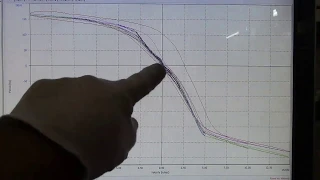
8 for the Baseline setup for the adjustments so when we go softest or stiffest on the damping I'm gonna also try to achieve a range between 0. 5 and 1. 2 damping ratio because then this I make sure that the engineers running this car can have a really wide range of possibilities for depending conditions temperature tracks curbs driver characteristics I want them to have enough freedom and then lastly for this first iteration I'll assume that the bump and rebound Behavior will be symmetrical so I'm just saying that I want the same damping ratio in bumping rebound we can change that later all of these were focused on the low speed characteristics of the damping so if we look at the damper curve we have the low speed region then we have the knee point and then we have the high speed region typically we could try to design the low speed to include all of the speeds when the car is rolling patching going up and down slowly and for high speed it could be when the the suspension is oscillating over bumps and over curbs so for this design we are going to Define after looking at for example data from a previous generation I would say that the knee point that I want for this damper is around 50 millimeters per second over here while I would like a scaling factor of 0.
3 of damping for high speed so if I have a given inclination which is the damping coefficient for low speed I can Define what is the scaling factor that I want for high speed in this case I'm using 0. 3 these are arbitrary numbers and with experience and working with these cards you can understand where is a good place to start with now that we understand the theory behind defining the damping ratio that we want for our system let's dive into the calculations themselves so first we Define write and platform Behavior we've discussed that the next step is to calculate the critical damping at the wheel then we need to define a Target damping ratio if we know the critical damping and the ratio of this critical damping we would like to have we can calculate the damping directly at the wheel now we are again at the syst at the system level and we need to convert from system level to component level which would be the damper how do we do that again we will use motion ratio and then we can end up with the damper curves that we need to send to our damper designer so for these calculations even though we have suspended Mass Springs and entire carcass and the entire stiffness in order to use the simple equations I want to use in this exercise we have to disregard the tires so all of the frequencies and the MP ratios we are discussing are only on the suspension if you want to go a little bit more complicated include tires then you cannot use linear equations you would need to for example run post trick simulations you can do that as a Next Step so first we calculate critical damping I already gave you the equation we just apply the stiffness and mesh of the system in order to come up with this number so we have a critical damping ratio of 13 Newton Second per millimeter let's now calculate the real damping that we want at the wheel well we know that the damping ratio we want is 0. 8 and we know that the damper ratio will also Define what is the real damping we have on the wheel we just follow this equation we manipulate it a little bit and if we want to use a 0.
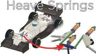
8 of the critical damping which is 13 we come up with a damping coefficient at the wheel of 10 Newtons second per millimeter this is at the system level in order to to convert from system level to to component level we have to use the motion ratio so the equation is very similar as we've used for Springs so by manipulating this equation over here we can convert from damping at the wheel at the system shoot the damping at the damper and we come up with a number of 18. why do we do that why do we calculate first on the system level before going to the component level well because for vehicle Dynamics what matters is what the car is saying it is what the Dynamics of the car is saying this is why we look at system levels this is why we see it as measured at the wheels and not as the component but in order to design a component we need to know the curve of the component and here we have it we have 18 Newton Second per millimeter a few other analysis that could be done after this in terms of damping would be to calculate damping ratio also in row and pitch for you to understand where you are and compare different adjustments you could calculate the transient lateral load transfer distribution or the roll stiffness distribution in train in transient with the damper so when you are cornering now the dampers are also influencing your load transfer the dampers are influencing the car balance so you can run that metric as well next you could perform pulse rig simulations because with simulations you can start connecting rear damping versus front to damping at the same time you can start looking at both axles at the same time and you can find best compromises so even though your initial number was 0. 8 when you run post rig simulations you can see that maybe a combination of 0.
9 on the front and 0. 6 on the rear will minimize different metrics such as load variation such as ride height variation and so on this is why this type of simulation is so powerful and lastly either using pulse rig simulation or pulse rig testing or testing the character track you can play with different bump and rebound bias this means that you could have a different damping ratio in bump rebound and this will affect the dynamic of the vehicle now that we are done with the theoretical calculations and manual equations I can show you another tool that I use so for example in this tool I can set all of the vehicle parameters I can also Define what motion ratios I have what view rates I have and what is the damping ratio that I want remember 0. 8 and a scaling factor of 0.
3 for the high speed and a knee point of 50 millimeters and let's say that I want a range of adjustment between 0. 5 damping ratio to 1.