hello and welcome to my next tutorial about prepomics this time i'll show you how to perform an axis metric analysis of a toroidal pressure vessel let's create a new model first and we have to choose a model space in the previous tutorials we covered plane stress and plane strain analysis and this time we'll discuss the access metric analysis so let's choose this type of model space and now i'll input the geometry um that's the the one here as you can see the geometry is divided into two parts so that's the result of partitioning in free
cad but it's not a problem i can just create a compound part from this and now i will specify the meshing parameters for this part i will use a maximum element size of one half meters and i will mesh this part to be able to define the actual analysis setup let's define the material first i will specify the typical properties for steel you don't know these properties from previous tutorials and you may notice that there are some some additional options for materials that were introduced in this version because i used in the new version and
released a few days ago and let's create a section this would be just a regular solid section using the material defined before since it's an axis metric analysis we don't have to define the thickness so just a regular solid section without any additional settings and now i will define you can see that amplitudes are also a new uh feature in the in this release and let's create a new step another new thing sleepwear step is something new and but we'll use just a regular static step this time and now let's define boundary conditions and clouds
something that we did in our previous tutorials when it comes to boundary conditions i will just fix these two edges in y direction and that's it for the boundary conditions and now i'll specify pressure and that will act on these two internal edges and the value of this pressure is 2 mega pascals i should also add that when it comes to axis metric analysis the models should be defined in xy plane as you can see this is done here and but also and they should use the y-axis as as as an axis of symmetry so
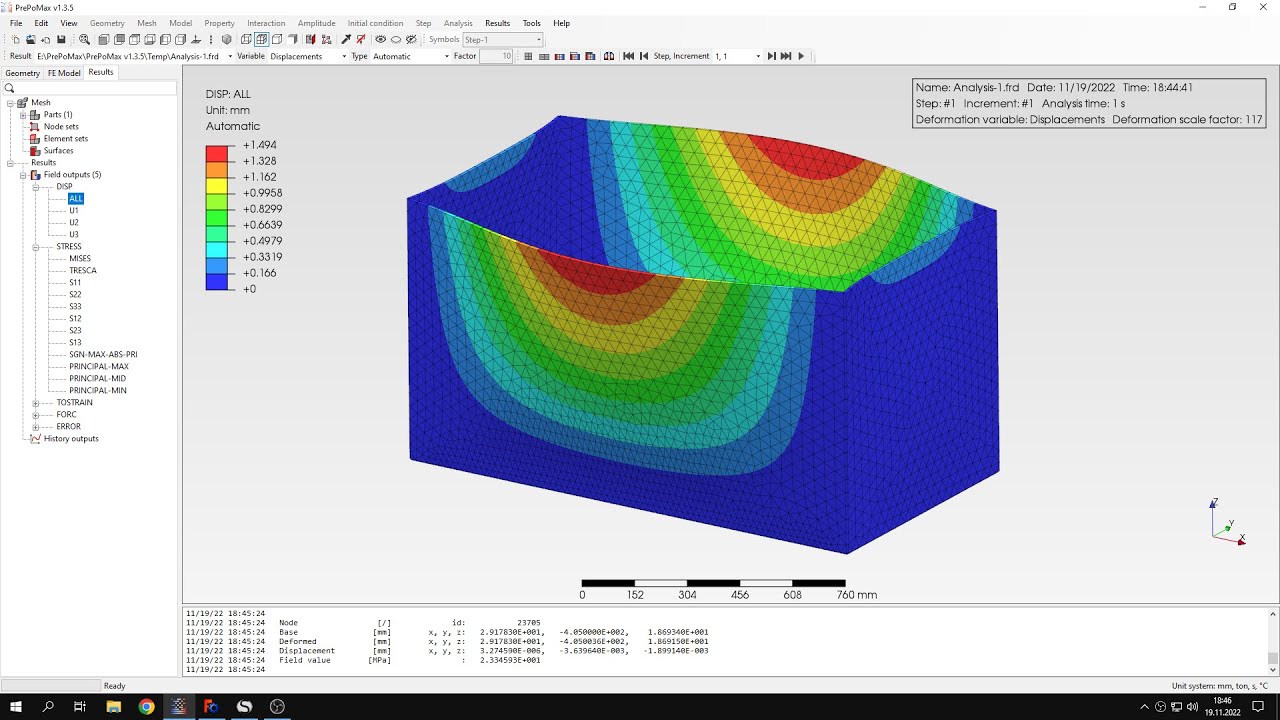
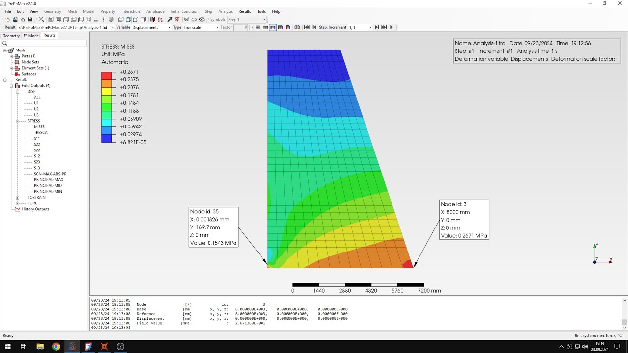
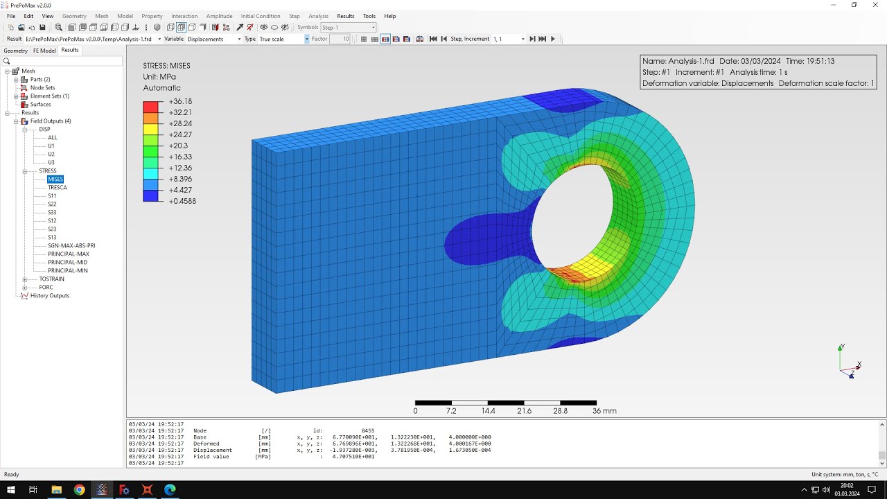
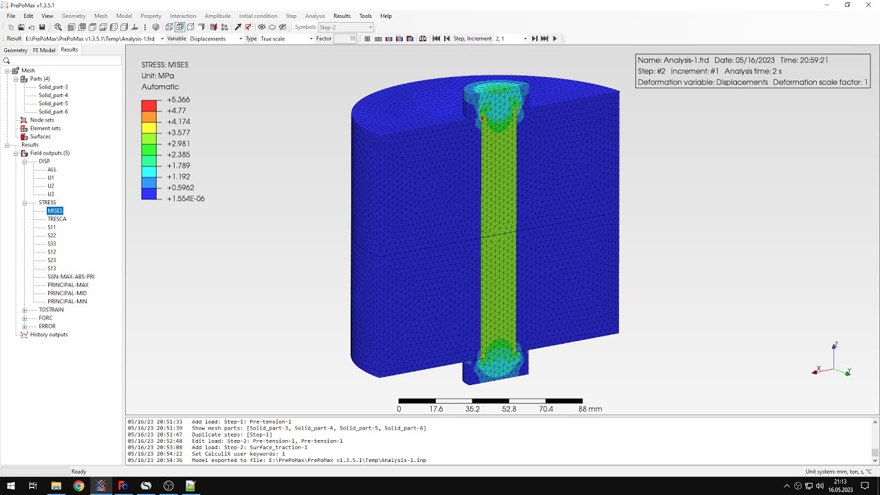
that's the requirement for axis metric analysis and what we should do now is switch to 3d outputs we will use we'll need this later on and that's it when it comes to the definition of the analysis so we can run this as you can see we already have the results it really was fast and now let's compare the results to the identical solution so let's check the analytical solution first of all let's verify the stresses so here's the information stress that we expect it was calculated for the radius denoted as r1 r1 is right here
and so let's check this in preparamex let's switch to full misses stress and use the query tool and to verify the stress around this location and you can see the values of the stress they are quite quite close to what we expect from the optical solution a bit higher but but still a pretty good result and it's around this this location the values are similar and now let's check the displacements as you can see i also calculated the value of the expansion of the radius of this toroidal pressure vessel and so let's switch to displacements
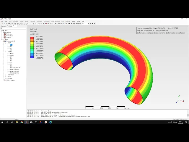
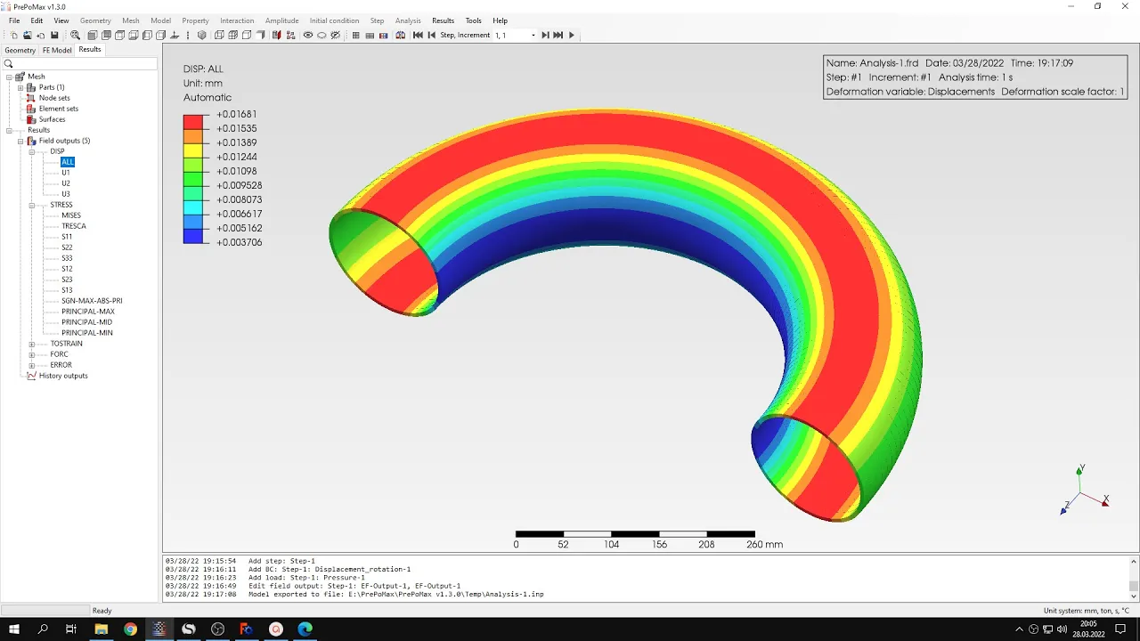
and let's see what what is the value for this location because the the calculation here was performed for the radius of it should be actually noted as r2 and this is the the radius right here and so we can see that the value is very close to the analytical solution and once again if we compare this with the value we obtained in this spreadsheet and now let's go back to into the visualization of the model and we can do one more thing before we end the post processing uh we can go to transformation and use
the circular pattern uh and since this is actually displayed in 3d and we can utilize this fact and let's specify the angle of 2 degrees that's because this is the expansion angle used by calculus to expand the axis metric elements to 3d ones and and i shall also specify the number of items it should be the angle that i want to actually visualize divided by two so let's specify for example 45 and let's see how this will look like as you can see this is the incorrect axis so let's change the the axis right here
and now and this will be the correct visualization quarter of the actual part that we want to visualize and now if i specify 90 degrees i will see half of this and of course if i specify more than that i can see the whole um dry down pressure vessel and this would take a while to compute this and so let's let's go back to the half of this of this geometry and i can also disable the display of of the edges to make this look better and this is how the model looks like if we
apply the if we apply the transformation feature and display the results on the 3d representation of the model of course i can switch between the different variables and visualize how it looks like you can see some artifacts from from the um because this is just polar pattern of of some segments uh two degree uh white of the uh of the model but still you can visualize the whole thing in 3d that's it for this purple next tutorial thank you very much for your attention as always feel free to ask any questions and suggest for future
tutorials in the comments have a nice day and see you in the next video