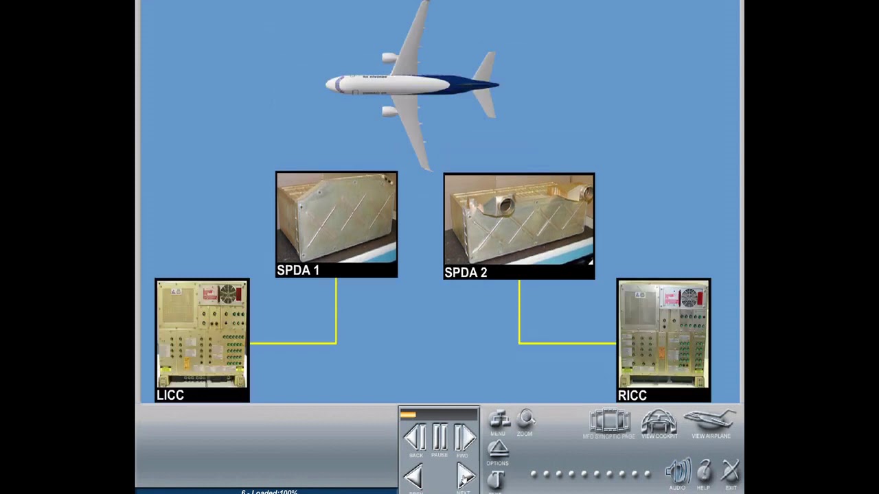
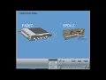
the air management system ams provides control over the bleed air system and the environment within the pressurized section of the fuselage it consists of the pneumatic system and the environmental control system ecs the cabin pressure control system cpcs is also part of the ams although it has a separate controller the ams controller connected to the secondary power distribution assembly to spda2 provides primary control for various aircraft subsystems such as bleed control environmental control hot air leak detection crew oxygen monitoring and wing and engine ice protection the ams controller also interfaces with the smoke detector in
the recirculation bay and provides fault detection isolation and reporting the ams controller has two channels that control the respective on-site systems in case of a channel failure the other channel is able to control the entire pneumatic air conditioning and anti-ice systems ams control is provided via the air conditioning and pneumatic control panel and the pressurization control panel installed on the overhead panel indication for the system is provided on the icas and the mfd environmental control system synoptic page the pneumatic system sources are engine bleed air apu bleed air or an external pneumatic source the pneumatic
system supplies regulated bleed air to the engine starter the anti-ice system the environmental control system and for water pressurization the main sources of bleed air for the pneumatic system are the engines various power settings cause changes in pressure and temperature output which have to be regulated to accomplish this regulation bleed air is taken from two different compressor stages low pressure port at stage number six and high pressure port at stage number ten a low stage bleed check valve prevents reverse flow of high pressure bleed air into the engine low pressure supply port the high stage
bleed valve regulates bleed air pressure at low power settings and the engine bleed valve regulates bleed air pressure at high power settings the temperature is regulated to a predetermined value by a pre-cooler which cools hot bleed air by fan air on ground or ram air or fan air in flight conditions with the engine bleed air buttons pushed in the ams controller automatically controls engine bleed air if the engine bleed button is pushed out engine bleed air is manually closed and a white bar will illuminate the apu is capable of supplying constant bleed air to the
pneumatic system on ground or in flight but it is used primarily as a ground pneumatic source for the environmental control system and for engine starting the apu bleed air duct is connected to the left hand bleed air manifold with a check valve to prevent engine bleed air from flowing to the apu when the engine is running the apu bleed valve controls apu bleed airflow to the pneumatic system with the apu bleed button pushed in the ams controller automatically controls the valve through the apu fadec if the apu bleed button is pushed out the apu fadec
will close it and the bar illuminates to meet ground air supply needs a dedicated engine start ground cart connection and an air conditioning ground cart connection are installed the check valves installed at each port prevent air from back flowing two ground connection ports are located on the lower section of the fairing area of the airplane overheat detection system monitors the pneumatic system for hot air leaks the system is comprised of dual overheat sensor loops which provide signals to the air management system controller this provides rapid and reliable overheat and leak detection for all parts of
the bleed air distribution system if an overheat sensor loop indicates a failure in its duct zone the amount shuts down the respective bleed system a message is sent to the icas and an amber bar illuminates on the applicable bleed button the normal operation of the pneumatic system is automatic and two independent networks provide complete segregation for pneumatic fault isolation the left engine normally provides bleed air to the left bleed manifold and the right engine normally provides bleed air to the right bleed manifold each manifold supplies a dedicated ecs pack and the onside anti-ice system if
more than one bleed air source is available the ams logic uses the following priority on-site engine opposite engine apu if activated note that apu bleed air cannot be used for the at ii system operation in flight in case of an engine bleed air source failure the crossbleed valve enables connection between the networks in this case the respective ecs pack and add ii system will be supplied from the opposite bleed source this is normal for engine starting operation the ecs packs one and two shall be closed if any of the following conditions occur a bleed air
source is not available for the pack the respective pack button is off any engine is starting and weight on wheels is true the respective engine is starting weight on wheels is false and the opposite engine is not starting any engine is starting and apu is the bleed source respective bleed system duct leak respective packs bit shutdown failures are present pack one or two fail icus message displayed the ecs packs are recovered if thrust levers are not set to max position and any of the following conditions occur thrust lever reduction the airplane is 500 feet above
takeoff field altitude for takeoff with two engines operating the airplane is above 9700 feet for takeoff fields at 8 000 feet or below and one engine in operative the airplane is above 15 000 feet for takeoff fields above 8000 feet and one engine in operative the airplane is above 9 700 feet during go-around in case one engine is inoperative ams automation ams controller functional logic provides automatic control of engine bleed apu bleed ecs packs and recirculation bay smoke detection according to the airplane operation and condition the engine bleed valve receives an electrical command to open
when the following conditions occur simultaneously respective bleed switch is set to auto respective engine bleed is available no fire is detected in the respective engine no bleed duct leak is detected the apu bleed valve receives an electrical command to open when the following conditions occur simultaneously apu bleeds which is set to auto apu bleed is available no apu and left bleed duct leak left engine bleed is unavailable at ii system not requested or anti-i system requested on and anti-i system is failed apu bleed source prioritization when the engine and apu bleed are available simultaneously the
ams controller will prioritize apu bleed air when the following conditions are simultaneously met opposite engine bleed pressure is below the minimum for engine start the airplane is on the ground ground speed is below 50 knots altitude is lower than fifteen thousand feet apu bleed is available and wing anti-i system is not requested the cross bleed valve is operating normally the cross bleed is commanded open if cross bleed switch is pushed in auto and any of the following conditions are met one side provides manifold pressure and there is not a bleed air source on the opposite
side apu bleed button pushed out for main engine start engine number two start in the air apu bleed off for engine number one start in the air no bleed leak unless starting an engine pack one and pack two shall be closed if any of the following conditions occur a bleed air source is not available for the pack the respective pack switch is off any engine is starting and the airplane is on the ground any engine is starting and the apu is the bleed source respective bleed system duct leak flight deck pack bit shutdown failures are
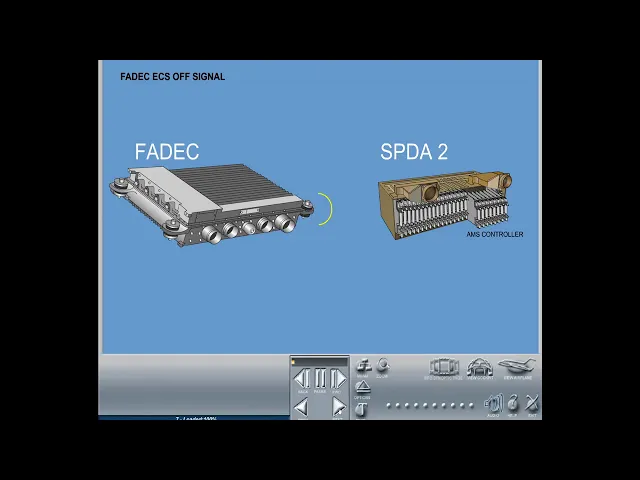
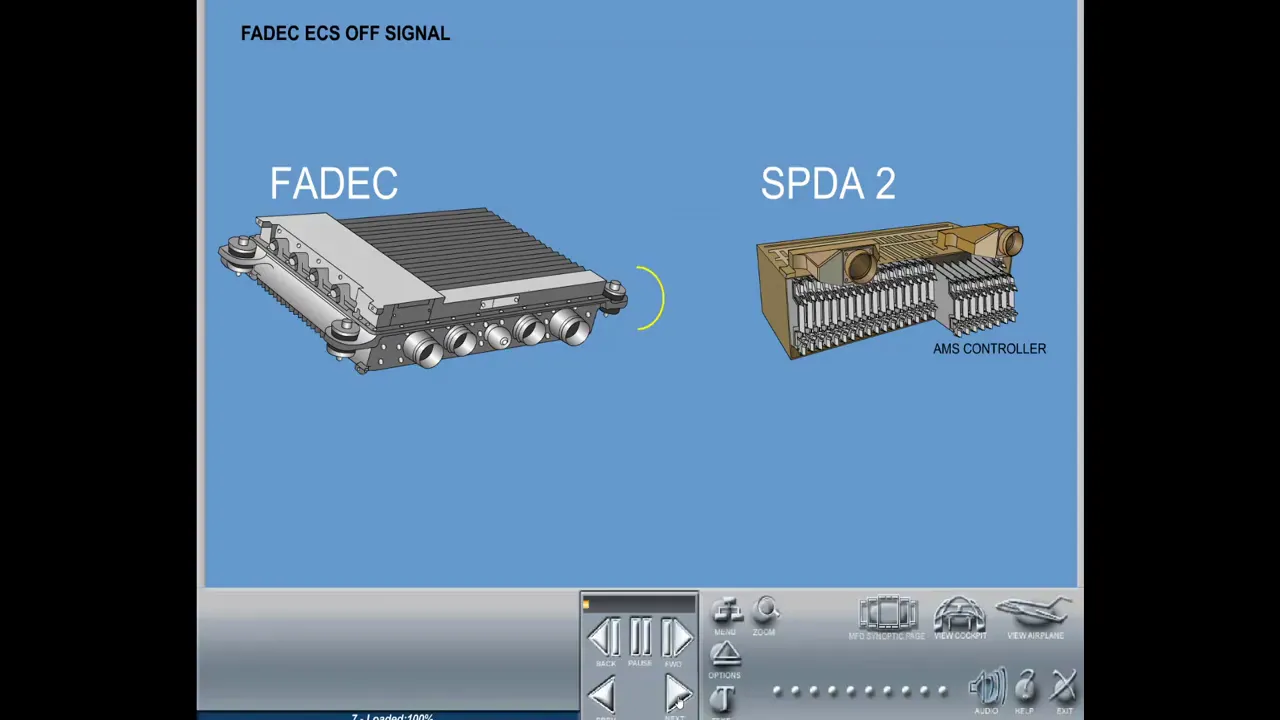
present eicas message displayed ecs selected off on the mcdu and ecs can be commanded off according to system logic the respective engine is starting weight and wheel is false and the opposite engine is not starting fedex ecs off signal the fadec may send an ecs off signal to the ams controller requesting that no bleed is extracted from the engine for the air conditioning system the fedex sets this signal depending on the tds input ref ecs off pressure altitude flight phase and engine inoperative detection the ams controller disregards the ecs off signal when the airplane is
flying over 15 000 feet the ecs off signal closes the packs during takeoff if any of the following conditions occur one engine inoperative and apu bleed is not available thrust lever set to max position and apu bleed is not available tds ref ecs set to off on the mcdu and apu bleed is not available tds ref ecs set to off and tds ref ai set to all on the mcdu the packs are recovered if any of the following conditions occur thrust lever reduction below take off go around the airplane is taking off with two engines
operating 500 feet above takeoff field altitude the airplane is above 9 700 feet for takeoff fields at 8 000 feet or below and one engine inoperative the airplane is above fifteen thousand feet for takeoff fields above eight thousand feet and one engine in operative the airplane is above 9 700 feet during go around in case one engine is inoperative the smoke detector mounted in the recirculation bay will command both recirculation fans to off when smoke is detected in the recirculation bay when smoke is detected on forward cargo compartment ventilation system fan operation is terminated the
check valve closes by mechanical springs the cargo outflow shutoff valve is commanded closed by ams controller when smoke is detected in the forward cargo compartment the environmental control system ecs uses bleed air from the pneumatic system to provide air conditioning for the cockpit and cabin filtered air recirculation conditioned air supply for gaspers and fan air cooling for avionics located in the electronic bays additionally an emergency ram air ventilation system is provided for cockpit smoke removal the embargo bay ventilation system provides adequate airflow to the forward cargo compartment the two ecs packs are installed in the
wing to fuselage fairing the ams controller controls the bleed airflow to each pack independently through the respective pack flow control valve during normal operation engine number one supplies bleed air to pack one while engine number two supplies bleed air to pack two via crossbleed a single bleed source can supply both ecs packs and a single pack is capable of keeping adequate cabin cargo hold pressurization and temperature air recirculation from the cockpit and passenger compartment is provided via two recirculation fans located in the pressurized section of the airplane the recirculation fans draw air from the recirculation
bays direct them to the mixing chamber and impel the air back into the distribution system the total flow entering the cockpit and the passenger cabin is made up of approximately 52 percent fresh air and 48 percent recirculation air with the recirculation button pushed in fan operation is automatic the fans will be commanded off if the dump button is pressed or if smoke is detected in the recirculation bay the gasper air distribution system provides air to each pilot and passenger position air flowing from the mixing manifold through the gasper check valve supplies the gasper ventilation system
when the gasper valve is opened air from the right recirculation fan supplies the gasper system during normal system operation the gasper shutoff valve remains closed it automatically opens whenever the gasper air supply exceeds 35 degrees celsius 95 fahrenheit this prevents hot air from blowing onto the passengers the forward ebay ventilation system has three fans which provide forced cooling air for the number one secondary power distribution assembly spda1 emergency integrated center eicc and all other avionics located in this ebay the fans draw air from the cockpit and expel air toward the underfloor recirculation bay a flow
sensor is used for fan flow health monitoring the center ebay ventilation system has three fans which provide forced cooling air for the center ebay electronics the left and right integrated control centers and spda2 the fans draw air from the rear cabin return and expel it towards the underfloor recirculation bay flow sensors are used for fan flow health monitoring the aft ebay air flows from the passenger cabin and is expelled towards the underfloor recirculation bay the ecs provides ventilation for live animals in the forward cargo bay this system contains a forward cargo fan on the side
of the bay to provide underfloor recirculation air into the bay the system also contains a shut off valve at the outlet of the bay that closes in the event of fire and thus preventing halon from leaving the bay in addition in the event of fire recirculation forward cargo fan is commanded off to prevent halon from entering the cabin the pac-1 ram air ventilation consists of a ventilation valve installed in the emergency ram air ducting that connects the ram air duct to the pac-1 outlet ducting the emergency ram air valve is commanded open anytime the airplane
is in flight and pack one and two are commanded off or failed and the airplane's flight altitude is less than twenty five thousand feet the pac-2 ram air ventilation consists of a check valve installed in the emergency ram air ducting that connects the ram air duct to the pac-2 outlet ducting the emergency ram air check valve does not require electronic control the emergency ram air check valve will be open whenever the pressure in the ram air ducting is greater than cabin pressure the flight deck and cabin zone temperature can be manually controlled by either using
the cockpit or the pax cabin selector knob on the air conditioning pneumatic control panel in the cockpit however control of the cabin zone temperature can be transferred to the respective selector knob on the flight attendant control panel by selecting the attendant position on the pax cabin knob in the cockpit with the optional two zone configuration installed each cabin zone has a separate flight attendant temperature select knob the respective control knobs are connected directly to the ams controller which in turn regulates the air temperature accordingly the ecs synoptic page in the cockpit displays temperature information of
the cockpit and cabin of the aircraft cockpit forward cabin and aft cabin set values display the temperature reference set by the switches on the cockpit and cabin selector panels cockpit forward cabin and aft cabin actual values display the actual temperature measured by the respective temperature sensors the electronic equipment rack ventilation system provides airflow for cooling of the in-flight entertainment electronic equipment installed in the electronic equipment rack in the lower compartment behind the aft partition of the aft cargo compartment when the aircraft is on ground a fan draws air from the electronic equipment rack and discharges
this air through the overboard air discharge port overboard the ife css power control panel in the cockpit allows the flight crew to manually disconnect electrical power to the electronic rack installed components in case of malfunction in the event of smoke generation resulting from failure of electronic equipment the system is automatically shut down a message is displayed on the icas and an oral warning is activated the cabin pressure control system cpcs controls the aircraft cabin pressure and provides maximum safety and comfort during all segments of flight and ground operation the system operates in either automatic or
manual mode normal operation is automatic the cabin pressure control system consists of the following main components one cabin pressure controller one cabin outflow valve one negative pressure relief valve one positive pressure relief valve and one static port one pressurization panel located on the overhead panel in the cockpit is installed for the crew to select the system modes insert the landing field elevation actuate the cabin outflow valve manually and to dump the cabin pressure in the event of an emergency system status information is indicated continuously on the icus and the ecs synoptic page while various messages
will be displayed on the icus in the event of failures the cabin pressure controller contains two identical control channels in auto mode one channel is in control and the other is in standby the channel in control uses actual cabin pressure from the cabin pressure sensors and various data from other aircraft systems such as ambient pressure engine power signals landing gear information barrow correction landing field elevation and cruise flight level to calculate the requested reference cabin pressure in manual mode both channels of the cabin pressure controller revert to standby mode the outflow valve position can then
be directly controlled by the pilots note manual mode is differential pressure limited but not cabin altitude limited and no automatic cabin depressurization on ground is provided the outflow valve modulates the cabin pressure by modulating airflow from the pressurized cabin into the surrounding environment it can be controlled automatically or manually the system also includes a pneumatically driven positive pressure relief valve which opens independently whenever differential pressure exceeds 8.6 psid to protect the aircraft structure against damages due to a positive overpressure a spring-loaded negative relief valve limits the negative differential pressure to minus 0.5 psid to protect
the cabin against damage the static pressure port senses the ambient static pressure and transmits it to the safety valve in order to allow the overpressure relief device to work the static port is electrically heated in order to assure there are no obstructions of sensing orifices due to icing the pressurization panel in the cockpit is directly connected to the cabin pressure control system controller and provides the following switches a rotary mode switch with three locked positions to select auto or manual modes and to set lfe landing field elevation control override when the switch is commanded to
lfe position the pressurization system remains in the automatic mode and only the lfe will be in manual mode a spring-loaded rotary selector knob with two momentary positions to increase or decrease the landing field elevation a spring-loaded rotary selector knob with two momentary positions to control the outflow valve manually and a guarded dump button when pressed the dump function is activated and a white stripe bar illuminates on the button during normal operation the pilot selects the cruise flight level and the landing field elevation in the fms before takeoff if no fms is available landing fuel elevation
must be manually selected using the rotary knob on the pressurization panel in this case the final cruise level will be calculated by the cabin pressure controller using actual ambience pressure during the flight the system now calculates a target cabin pressure and a corresponding pressure rate of change for each of the following cabin pressure control system flight modes ground the aircraft is on the ground but not within the takeoff run taxi mode the airplane is on the ground with doors closed and both engines running at a rotation into higher than 60 percent takeoff the aircraft is
performing the takeoff run climb the aircraft climbs to the crew's flight level proves the aircraft is flying at a constant altitude descent the aircraft is ascending towards the landing field and abort the flight is aborted and the aircraft returns to the takeoff field icas indication lfe will return to takeoff field elevation if the present pressure altitude is below ten thousand feet or five thousand feet above field elevation information from the fedex the adc and the fms are used with the cabin pressure controller to determine the current flight mode the cabin pressure control system operates for
aircraft ceilings up to forty one thousand feet during cruise below thirty seven thousand feet the nominal differential pressure will be limited to seven point eight psid while cruising above 37 000 feet will limit the differential pressure to 8.4 psid as a result maximum cabin altitude at aircraft ceiling is limited to 8 thousand feet a cabin altitude high warning is generated whenever the cabin altitude rises above nine thousand seven hundred feet note in case of high airfield operation the warning will be active for a cabin altitude of 500 feet above takeoff field elevation for cabin altitudes
exceeding 14 500 feet the outflow valve will close automatically to prevent the cabin from climbing further the system automatically limits differential pressure by opening the outflow valve or in the event of failure by opening the safety valve the automatic mode provides a single action dump function this function is used in the event of emergency evacuation smoke evacuation or for fast cabin depressurization selection of the dump button will deactivate the ecs packs and the recirculation fans and then depressurize the cabin at a rate of two thousand feet per minute up to twelve thousand four hundred feet
by controlling the outflow valve when the cabin altitude reaches twelve thousand four hundred feet the outflow valve is commanded to close and the cabin altitude will rise due to natural leak the cabin can be depressurized to higher altitudes using the manual mode note if pressurization dump button is pressed a second time the system returns to normal operation rotating the pressurization mode selector knob to the manual position allows manual control of the outflow valve when manual mode is selected both channels of the cabin pressure controller revert to standby state but only one channel performs the manual
operation the channel selection is automatic note in manual mode there is no automatic cabin depressurization on the ground after landing the following information is indicated continuously on the icus cabin altitude cabin pressure rate cabin differential pressure landing field elevation additionally outflow valve position is continuously indicated on the ecs synoptic page and safety valve status will be displayed if the valve is open the following icus advisory caution and warning messages will be displayed on the icus in case of failures the advisory message pressurization auto fault will be displayed if one channel of the controller can no
longer perform auto mode but the second channel is fully operational the caution message pressurization auto fail indicates that both channels fail to perform auto mode the crew must select manual mode and control the cabin altitude manually using the conversion tables in the aircraft manual the caution message pressurization manual fail is displayed when both channels fail to perform manual mode the warning message cabin altitude high together with a red cabin altitude indication will be displayed when the cabin altitude exceeds 9700 feet additionally an oral warning will say cabin cabin cabin you