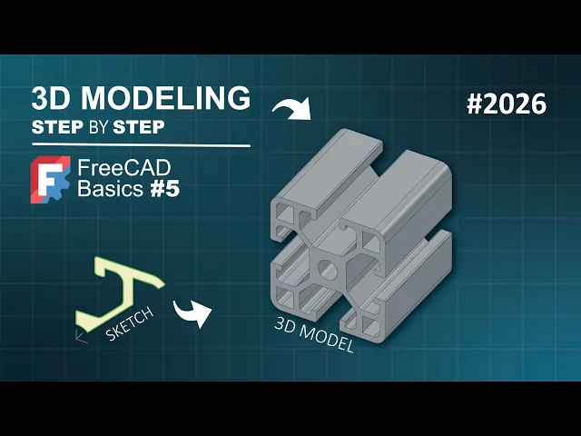
In the last video on the channel, we modeled our free 3D object in a way that allowed us to save time. In this video, it won't be very different. The goal is to model something simple, but that will help us understand some features of the FreeCAD workbenches.
This time, however, the sketch will be a bit more refined. The idea is to create the design in the Part Design workbench, so we can choose to start with a document based on that workbench, and a body object will be added to that document. Next, we will create a sketch on the XY plane of the body object.
We are automatically in the Sketcher workbench, and the idea here for the V-slot is to design this half of the geometry, because as you can see, the shape of the object allows that. So, basically, we will need to use a construction line as a symmetry axis in this sketch. This is something that will give us precision in the operations we will perform to reach the final model.
Let's start by creating the line that we'll use later as the axis of symmetry. Let's click on this icon here to change the geometries to construction mode, and then let's select the line tool and start our line on the origin axis. Let's use the dimension tool to set the dimensions of this construction line.
Let's start by selecting this point here and the vertical axis and set the horizontal distance of 20 mm. Next, let's create an angle dimension. Let's select the construction line and the horizontal axis 45°.
Let's hide these all dimensions by pressing this icon and change the geometries to normal mode by clicking on this icon, toggle construction geometry. And next, let's select the polyline tool and start our geometry on the vertical axis. Create a vertical line, next a horizontal line, and now this line here, and next a vertical line, horizontal, vertical, horizontal, and vertical again, and next a horizontal line.
Escape the tool, and now let's start another geometry here on the on the construction line. Let's create a vertical line, and next a horizontal line in this way. Let's escape the tool, and next let's select the arc from center.
Let's click on the origin point and create a this arc. Next, let's click on the construction line and create a this arc in this way. Now, let's click on the center point and create a this arc here.
Okay, let's escape the tool, and next let's select the line tool and create a this line between these two points, and another line between these two end points. Escape the tool, and next let's go to Sketcher tools and select fillet. Let's create a fillet here on this corner, and a fillet here between these two lines, and another fillet in these two lines here, and a fillet here and here on this corner.
So, let's escape this tool. Let's select a this point here in this way and apply a tangent constraint. Go to Sketcher constraints and click on this icon to apply a tangent constraint.
Let's do the same thing for this point here. tangent And next, let's select a this arc here. Let's select this arc here, this arc, and this one here.
Uh let's apply an equal constraint because they have the same radius. Go to Sketcher constraints and click on this icon to apply equal constraint. Now, let's select a this arc, this arc here, this one, and this arc, and let's apply the same constraint, equal constraint.
Next, on the Sketcher constraints, let's select parallel constraint and make a this line and this line parallel. Change the geometries to construction geometries, and select line tool, and now let's create a line between this point and this line here, a vertical a horizontal line. Next, let's create another line here, a vertical line, and another line, a horizontal, and another line, a horizontal line this time, and here from this point to this line here, let's create a vertical line.
The idea of these four construction geometries is to use them as a way to fix the the the thickness of this model. So, we'll select a this construction geometry, this line, this line, and this line here, and next let's apply an equal constraint. Go to Sketcher constraints and click on equal constraint, and here we have this.
10 degrees of freedom, as you can see. Let's select dimension tool, click on this arc here, and click off. The radius here must be 0.
5, so set this value, and then press enter, and here we have this. Next, click on this arc here, click off, and the radius for this arc is 2 mm. Okay, and now from this line to this line here, the distance is 1 mm.
And the thickness of this model is 2 mm, so we can click on this line, for example, this construction line, and set 2 mm. Now, we have 6 degrees of freedom, as you can see. Okay, we can start by selecting this point here and the vertical axis and set the distance of 10 mm.
And now, from this end point, from this point to the vertical axis, the distance is 4 mm. And now, and now, this line here and this line here, the distance is 4 mm. Okay, next let's click on this line here and set its length to 3 mm.
And this arc here, the radius is 3. 5. Okay, one degree of freedom.
What is missing to do is to select a this line here and the horizontal axis and set the distance to 20 mm. Okay, now if you press this icon two times, as you can see, we have this. This sketch is fully constrained, as you can see, we can close it without problems.
And here we have the sketch on the tree view, as you can see. The next thing to do is to extrude the sketch here using the pad feature of Part Design workbench. So, with the sketch selected in the tree view, let's click on the pad tool.
Let's reverse the duration of this extrusion in the pad parameters and change its length to something like 40 mm. Click off, and as you can see, this is a preview, as you can see here. Let's press okay to finish this, and here we have the free shape of the V-slot model.
Now that we have the free shape of the part, we can perform operations that will allow us to reach the final form of the free 3D model. To replicate this half along the Y axis, we need to use the multiform tool. This is the only transformation tool that allows more than one transformation, so that's why we will use it.
So, let's go to the tree view, and then body object, let's select this pad feature, and let's go to the Part Design transformation features toolbar. These all features here, and let's click on this icon, multiform. On the multiform parameters, as you can see, we are transforming two shapes.
We are transforming this pad feature here, not the body object. Okay, so let's go to transformations, and let's add the first mirror transformation. Right click on mouse and select this option, add mirror transformation.
And as you can see, it's working fine here, but if you want, we can use the first line that we created as the axis as the plane for this mirror. To do that, we go to plane, and we click on it, and then we select construction line one. Press okay, and now to replicate this half here, we can use the polar pattern transformation.
Okay, let's do that. Go to transformations, right click on mouse and select add polar pattern. And as you can see, here we have two occurrence in the Y axis.
Okay, let's change here to four occurrence, and and let's let's click okay, and then okay to finish this feature. And this is the final result. Thank you for watching this video.
If you find this video useful, please don't forget to hit like and share this video with your friends. Thank you. I hope to see you in the next video.