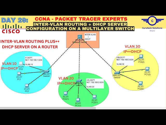
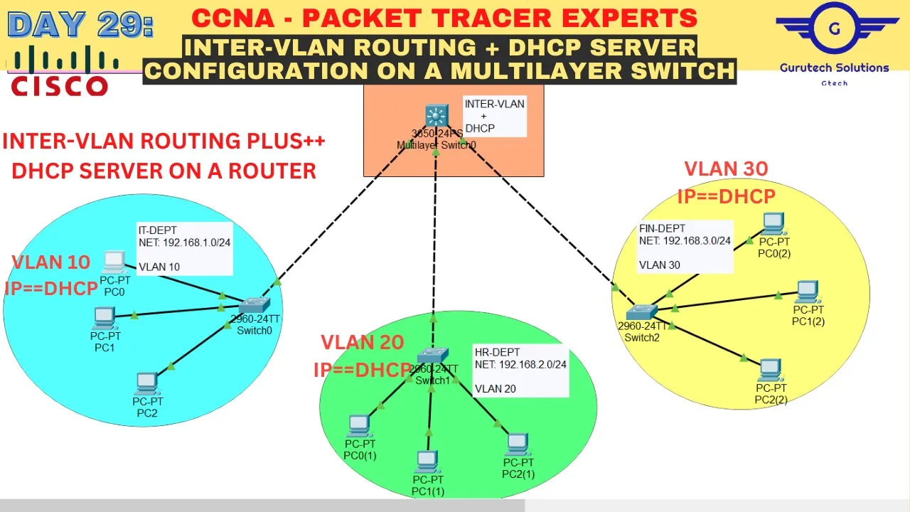
bless the day guys and peace be upon you this morning so in this video we're going to learn how to configure intervalent routing plus DP server on a multi-layer switch or layer three switch so we're going to use this smart layer switch to do inter routing and to act as our DCP server in this network to provide it Department HR department and finance Department Dynamic IP address allocation all right okay so I'll open our Google space sheet I'll let you know that we doing part two of the inter routing plus d DCP Ser configuration using much l switch or lay three switch okay all right so without any further Ado I'll open our gole I mean our notepad to highlight the steps that we're going to follow to achieve the objective the first step is always the drawing the Neary necessary topology decorating and doing comments so you can see I've uh I do this topology using various component the first component is a m layer switch I used 3650 3650 M lay switch make sure you choose 3650 m l switch then if we move down I chose 36 I mean 29 60 access layer switches okay then the normal computers and I did comments here this one this one is interv routing plus DP here is it Department okay that's our it Department the network is there plus the villain it's Department Network villain finally finance department Network and villain so let's go to the second step that's done configure Vance name them Ascend ports and configure TR ports between the switches so in every switch here in every switch we're going to configure villan as per the comments here so for example in this switch here it's going to belong to V 10 here V 20 here V 30 okay and we've been told also to configure TR between the switches so any link connecting switch to switch will be trun so in my topology you can see this is f01 f01 and f01 so f01 on all these switches should be trunk but from f02 to 24 will be access port with v 10 with villan 20 or with v 30 okay so let's begin that I'll go to this switch and say enable uh config T okay then let's create villain we've been told the second step is to create villain name them and send parts so let's say villain 10 we name as it we exit then we assign the V ID to Ports so interface range fa02 224 because fa01 should be our now from2 to 24 we'll be accessing V and 10 okay so let's say switch mode mode access let let them be access first then switch mode access V 10 exit then here configure TR between the switches so our f one should be our TR okay so interface f01 switchboard mode just say switchboard mode TR that's all so we do the same configuration in all the switches the two remaining switches the same configuration what will change just the V numbers okay all right so I'll do it very very fast save time okay guys so I've done uh I've done the part two of uh of the guide how to we configure villain naming them and assigning parts to the villain IDs okay and also uh configuring TRS between the switches but we've not done for the M layer switch here we have to do the same for the M layer Swit here okay remember we've configured an individual switch with the respective villain so all those villain should will be configured here also V 10 V 20 and 30 okay we have to configure all the villance here also okay so the first step guys you can see the 3650 M which is always powered off so we have to power it on how do we power it on just click on it just then drag this AC power supply and put it into that empty slot just closed give it like 10 minutes until you see the the links turn to Orange then you click it again okay all right so you have to power it on first before you start configuration okay just click on it again come to C and say no remember we're still on number two configure vill name them assign to port and configure TR truns between the switches so on the M switch we we only not going to do this one but you have to configure all the villain in the network we have to name them and we have to configure trans so let's just go here I say enable uh config te then V 10 uh name it then we come to V 20 uh name HR then we come to 30 and name Finance fin exit then the final part configure trans between the switches okay on the M switch we're not going to assign them to vill to Port okay we're only going to configure TRS okay all right so let's identify TR ports TR ports will be this one gig 0 gig gig 102 uh gig 103 and gig 104 so from gig 102 to Gig 104 should be transport so just say interface range gig 1/ 0/ 2 to 4 okay switch P mode to be track and it enter exit and do right so we done with number two okay so let's go to step number three step number three is to enable IP routing on the ml switch remember we want this m layer switch to act as both a switch and the router by default is always the switch so you have to make it like a switch and rout by enabling routing you just click on it and just WR this command IP routing to enable routing on that M switch that's all if you don't do this one it will never work as a rou good so let's go to the fourth step the first step is to create svis on the M Swit as for the respective V it and assign the IP addresses so what what are svis svis are switch virtual interfaces so switch virtual interfaces are for as are like we created how many vill here vill 10 vill 20 and villan 30 so svi will be interface of villan 10 interface of villan 30 or interface of villan 10 so let's create svis as per the villan ID so we just say interface with Lan 10 okay and we Ender right then we assign it IP address so the IP address should be the first IP address in this sub IP it Department okay just say IP add to be 1 and2 16811 2555 255 U 25. 0 and each enter that's all we've created svi for it department and added it IP address okay exit so let's do for uh HR department which is F 20 okay then we we give it a p add of 2. 1 and the SS should act as the default gateway of each respective Department okay and finally we 30 um 3.
1 this is now intervent routing part do right so we have done that part is for intervent routing and we are done doing intervent routing on that much l Swit so let's move to DSP we're going to create pools assign Network addresses default gateway and DNS so the default gateway should be the IP address of the the SVS that we just created okay all right so let's create pools for DCP the first thing that you should always do when you're configuring DCP make sure you enable that service just say service DSP and it enter now start creating pools IP DP pool for let's say it Department it pool okay and assign a network of network of um 1 and2 168 1. 0 I think I made a mistake here the networks were like 10 or something but I used 1 dot 2 Dot 3 dot it should be 10 dot 20 dot or 30 dot but no problem let's just go this we can edit here easily then in the configuration okay all right so uh sub of 2555 255. 255 do0 okay and H enter Then default default router should be the P add the SV that we created before V it was2 168 1.
1 then you send DNS DNS to be DNS to be the same as default get to as now okay uh exit so before I go to h Pool I'll just go here and modify this as one do something not 10 do something this one also like 20 102 something not 20 something and here also uh 3 something not 30 something okay all right so let's proceed to create I pool for HR so I just try to retrieve um yes so just say HR pool HR then the network the network should be 2 do something uh default router should be the appear the um the svi for 20 which was 2. 1 before I mean DNS now will remain as um default router as per now and finally let's go to Finance pool three something um default router should be 3 something 31 and DNS to be like uh the same as default rout exit and do right so when you come back here and uh we say exclude the ranges of IP address that should not be assigned to host dynamically so let's exclude just say IP DCP uh excluded address to be let's exclude first for IT department 192. 168.
1. 1 2 1 21681 10 so we don't want the DCP server to assign host in IT department IP address from 1 to 10 okay so the same should apply for H HR department HR department should now be two do something to uh here two now finally finance and do R okay so number seven go to Every PC and change the option to DCP test commun communication so we going to every PC here and change the option to gcp so let's start go to static first and change it to DCP it should pick IP address from 11 because from 1 to 10 was excluded okay all right so DCP is successful when I come back here I should take two something I turn it back to static then DCP first so that's successful then we go finally to finance department come to IP configuration um wait until it get three or something well that's good so let's go go here and try to Ping let's go here and try to ping ping 1 12. 1 168.